manuals.online logo
Brands
  1. Home
  2. •
  3. Brands
  4. •
  5. Sauder
  6. •
  7. Indoor Furnishing
  8. •
  9. Sauder Clifford Place 421113 User manual

Sauder Clifford Place 421113 User manual

Need help? Visit Sauder.com to view video assembly tips or chat with a live rep.
Prefer the phone? Call 1-800-445-1527.
Share your journey!
sauder.com
Business or pleasure.
Works both ways.
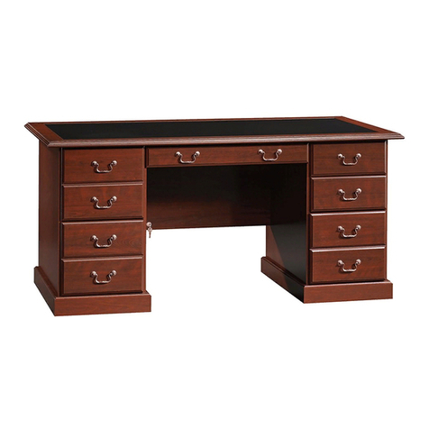
Executive Desk
Cliord Place Collection | Model 421113
NOTE: THIS INSTRUCTION
BOOKLET CONTAINS IMPORTANT
SAFETY INFORMATION.
PLEASE READ AND KEEP FOR
FUTURE REFERENCE.
English pg 1-38
Français pg 39-43
Español pg 44-48
Lot #: 501392
Date Purchased: __________________
01/27/17
Be sure to give us a ring before
making any returns. 1-800-445-1527
Assembly Tools Required
Part Identification
Hardware Identification
Assembly Steps
Français
Español
Safety
Warranty
Hammer
Not actual size
No. 2 Phillips Screwdriver
Tip Shown Actual Size
Skip the power trip.
This time.
Table of Contents
2-3
3-4
5-38
39-43
44-48
49-50
51
Part Identification
A RIGHT END (1)
B LEFT END (1)
C LEFT UPRIGHT (1)
D RIGHT UPRIGHT (1)
E TOP (1)
F BACK (2)
G MODESTY PANEL (1)
H BOTTOM (2)
I SHORT TOP MOLDING (2)
J LONG TOP MOLDING (1)
K BRACE (4)
L BOTTOM MOLDING (4)
M FOOT (8)
N KEYBOARD SHELF (1)
O KEYBOARD HINGE FRONT (1)
P KEYBOARD FRONT (1)
Q SMALL DRAWER FRONT (2)
R DRAWER FRONT (2)
S LARGE DRAWER FRONT (2)
T SMALL LEFT DRAWER SIDE (2)
U SMALL DRAWER BACK (2)
V SMALL RIGHT DRAWER SIDE (2)
W LEFT DRAWER SIDE (2)
X DRAWER BACK (2)
Y RIGHT DRAWER SIDE (2)
Z LARGE LEFT DRAWER SIDE (2)
AA LARGE DRAWER BACK (2)
BB LARGE RIGHT DRAWER SIDE (2)
CC DRAWER BOTTOM (6)
DD MODESTY PANEL SHELF (1)
Page 2 www.sauder.com 421113
Part Identification
åWhile not all parts are labeled, some of the parts will have a label or an inked letter on the edge
to help distinguish similar parts from each other. Use this part identification to help identify similar parts.
Now you know
our ABCs.
A
B
C
D
E
F
F
G
H
H
II
J
K
KK
K
L
LL
L
M
M
M
M
N
O
P
QQ
RR
S
S
T
T
U
U
V
V
W
W
X
X
Y
Y
Z
Z
AA
AA
BB
BB
CC
CC
CC
CC
CC
CC
DD
Hardware Identification
(EXTENSION SET SHOWN SEPARATED)
LONG EXTENSION
RAIL - 4
EE LONG EXTENSION
SLIDE - 4
FF
SHORT EXTENSION
RAIL - 2
GG SHORT EXTENSION
SLIDE - 2
HH
Page 3www.sauder.com421113
Hardware Identification
åScrews are shown actual size. You may receive extra hardware with your unit.
ANGLED HEAD
CAM SCREW - 50
3STRAIGHT HEAD
CAM SCREW - 24
4
SMALL HIDDEN
CAM - 24
2
LARGE HIDDEN
CAM - 50
1
1/2" PAN HEAD SCREW - 36
20
LONG WOOD
DOWEL - 42
6
SILVER 1/2" FLAT HEAD SCREW - 16
19
BLACK 1/2" FLAT HEAD SCREW - 48
18
SHORT WOOD
DOWEL - 16
5
1-1/8" FLAT HEAD SCREW - 18
16
1-1/2" FLAT HEAD SCREW - 24
15
PULL - 6
11
HINGE - 2
8
FILE GLIDE - 4
13
9/16" WAFER HEAD SCREW - 2
17
CAM COVER
CARD - 1
14
LEVELER - 8
7GROMMET - 4
9GROMMET and
CAP - 2
10
FILE HANGER - 4
12
LEFT DRAWER
SLIDE - 4
LL
RIGHT DRAWER
SLIDE - 4
KK
LEFT CABINET
RAIL - 4
JJ
RIGHT CABINET
RAIL - 4
II
Page 4 www.sauder.com 421113
QTY-26
COVERS
Angled head Straight head
Step 1 Look for this icon. It means a
video assembly tip is available at
www.sauder.com/services/tips
å Assemble your unit on a carpeted floor or on the empty carton to avoid scratching your unit or the floor.
å Turn six ANGLED HEAD CAM SCREWS (3) into the LEFT END (B).
å Push two LONG WOOD DOWELS (6) into the short edge of the LEFT END (B).
å Fasten two LEFT CABINET RAILS (JJ) to the LEFT END (B). Use six BLACK 1/2" FLAT HEAD SCREWS (18) through the
2nd, 3rd, and 5th holes as shown.
å Separate a LONG EXTENSION SLIDE (FF) from a LONG EXTENSION RAIL (EE) as shown in the upper diagram. Be
prepared, the parts are greasy.
å Fasten the LONG EXTENSION RAIL (EE) to the LEFT END (B). Use three 1/2" PAN HEAD SCREWS (20).
å NOTE: For each EXTENSION RAIL, turn a SCREW into the holes shown in the upper diagram. Then, slide the inner
cartridge of the EXTENSION RAIL in to find the other two holes that line up with the holes in the LEFT END. Turn the
SCREWS into those holes.
å NOTE: The LONG EXTENSION SLIDE will be used later for the LARGE DRAWERS.
6
Angled head
Open end
2
2
1
1
3
3
4
4
5
5
1/2" PAN HEAD SCREW
(3 used for the EXTENSION RAIL)
20
Roller end
3
BLACK 1/2" FLAT HEAD SCREW
(6 used for the CABINET RAILS)
18
Push the black lever down and pull the SLIDE from the RAIL.
EE
EE
FF
B
JJ
JJ
(6 used)
Page 5www.sauder.com421113
Use this hole. Use these holes.
Step 2
å Turn six ANGLED HEAD CAM SCREWS (3) into the LEFT UPRIGHT (C).
å Fasten two RIGHT CABINET RAILS (II) to the LEFT UPRIGHT (C). Use six BLACK 1/2" FLAT HEAD SCREWS (18)
through the 2nd, 3rd, and 5th holes as shown.
å Separate a LONG EXTENSION SLIDE (FF) from a LONG EXTENSION RAIL (EE) as shown in the upper diagram. Be
prepared, the parts are greasy.
å Fasten the LONG EXTENSION RAIL (EE) to the LEFT UPRIGHT (C). Use three 1/2" PAN HEAD SCREWS (20).
å NOTE: For each EXTENSION RAIL, turn a SCREW into the hole shown in the upper diagram. Then, slide the inner
cartridge of the EXTENSION RAIL in to find the other two holes that line up with the holes in the LEFT UPRIGHT. Turn
the SCREWS into those holes.
å NOTE: The LONG EXTENSION SLIDE will be used later for the LARGE DRAWERS.
Angled head
Open end
2
2
1
1
3
3
4
4
5
5
1/2" PAN HEAD SCREW
(3 used for the EXTENSION RAIL)
20
Roller end
3
BLACK 1/2" FLAT HEAD SCREW
(6 used for the CABINET RAILS)
18
Push the black lever down and pull the SLIDE from the RAIL.
EE
EE
FF
C
II
II
(6 used)
Page 6 www.sauder.com 421113
Use this hole. Use these holes.
Step 3
å Flip the LEFT UPRIGHT (C) over.
å Turn three ANGLED HEAD CAM SCREWS (3) into the LEFT UPRIGHT (C).
å Push two LONG WOOD DOWELS (6) into the short edge of the LEFT UPRIGHT (C).
å Separate a SHORT EXTENSION SLIDE (HH) from a SHORT EXTENSION RAIL (GG) as shown in the upper diagram.
Be prepared, the parts are greasy.
å Fasten the SHORT EXTENSION RAIL (GG) to the LEFT UPRIGHT (C). Use three 1/2" PAN HEAD SCREWS (20).
å NOTE: For each EXTENSION RAIL, turn a SCREW into the hole shown in the upper diagram. Then, slide the inner
cartridge of the EXTENSION RAIL in to find the other two holes that line up with the holes in the LEFT UPRIGHT. Turn
the SCREWS into those holes.
å NOTE: The SHORT EXTENSION SLIDE will be used later for the KEYBOARD SHELF.
å Insert a GROMMET (9) into the large hole in the LEFT UPRIGHT (C).
6
Angled head
Open end
1/2" PAN HEAD SCREW
(3 used for the EXTENSION RAIL)
20
3
Push the black lever down and pull the SLIDE from the RAIL.
C
9
GG HH
GG
Page 7www.sauder.com421113
Use this hole. Use these holes.
Step 4
å Push fourteen LONG WOOD DOWELS (6) into a BACK (F), BOTTOM (H),
and two BRACES (K).
å Turn two ANGLED HEAD CAM SCREWS (3) into the BACK (F).
å Insert a GROMMET (9) into the large hole in the BOTTOM (H).
å Repeat this step for the other BACK (F), BOTTOM (H), and BRACES (K).
Angled head
3(4 used)
(2 used)
(28 used in this step)
6
6
6
6
6
9
F
H
K
K
Page 8 www.sauder.com 421113
Step 5
(4 used in this step)
å Push two LARGE HIDDEN CAMS (1) into a BOTTOM (H).
å Fasten the BOTTOM (H) to a BACK (F). Tighten two
LARGE HIDDEN CAMS.
å NOTE: Be sure the WOOD DOWELS in the BOTTOM
insert into the BACK.
å Repeat this step for the other BACK (F), and BOTTOM (H).
F
H
Rounded edge
Surface with
HIDDEN CAMS
The CAM SCREWS
must be here.
3
21
1
The arrow must
point toward the
edge of the board.
1
Arrow
Page 9www.sauder.com421113
Step 6
å Push six LARGE HIDDEN CAMS (1) into a BACK (F),
BOTTOM (H), and two BRACES (K).
å Fasten the LEFT END (B) to the BACK (F) and BOTTOM (H).
Tighten four LARGE HIDDEN CAMS.
å NOTE: Be sure the WOOD DOWELS in the BACK and
BOTTOM insert into the LEFT END.
å Fasten two BRACES (K) to the LEFT END (B). Tighten two
HIDDEN CAMS.
å NOTE: Be sure the WOOD DOWELS in the BRACES insert
into the LEFT END.
3
21
1
The arrow must
point toward the
edge of the board.
F
H
K
K
B
1
1
1
Arrow
Arrow
Arrow
Page 10 www.sauder.com 421113
Step 7
å Push six LARGE HIDDEN CAMS (1) into the BACK (F),
BOTTOM (H), and BRACES (K).
å Fasten the LEFT UPRIGHT (C) to the BACK (F), BOTTOM (H),
and BRACES (K). Tighten six LARGE HIDDEN CAMS.
å NOTE: Be sure the WOOD DOWELS in the BACK, BOTTOM,
and BRACES insert into the LEFT UPRIGHT.
3
21
1
The arrow must
point toward the
edge of the board.
H
C
F
K
K
1
1
Page 11www.sauder.com421113
Step 8
å Turn and tighten four FEET (M) into the BOTTOM (H).
H
M
M
M
M
Remember:
Righty tighty.
Lefty loosey.
Page 12 www.sauder.com 421113
Step 9
å Push four SHORT WOOD DOWELS (5) into the BOTTOM (H).
å Fasten two BOTTOM MOLDINGS (L) to the BOTTOM (H). Use
four 1-1/8" FLAT HEAD SCREWS (16).
1-1/8" FLAT HEAD SCREW
(4 used in this step)
16
H
5
L
Page 13www.sauder.com421113
L
5
Step 10
å Turn four LEVELERS (7) into the FEET (M).
å NOTE: The LEVELERS will be adjusted in the last step.
7
M
M
M
M
Page 14 www.sauder.com 421113
Step 11
å Turn six ANGLED HEAD CAM SCREWS (3) into the RIGHT END (A).
å Push two LONG WOOD DOWELS (6) into the short edge of the RIGHT END (A).
å Fasten two RIGHT CABINET RAILS (II) to the RIGHT END (A). Use six BLACK 1/2" FLAT HEAD SCREWS (18) through the
2nd, 3rd, and 5th holes as shown.
å Separate a LONG EXTENSION SLIDE (FF) from a LONG EXTENSION RAIL (EE) as shown in the upper diagram. Be
prepared, the parts are greasy.
å Fasten the LONG EXTENSION RAIL (EE) to the RIGHT END (A). Use three 1/2" PAN HEAD SCREWS (20).
å NOTE: For each EXTENSION RAIL, turn a SCREW into the hole shown in the enlarged diagram. Then, slide the inner
cartridge of the EXTENSION RAIL in to find the other two holes that line up with the holes in the RIGHT END. Turn the
SCREWS into those holes.
å NOTE: The LONG EXTENSION SLIDE will be used later for the DRAWERS.
6
Angled head
Open end
2
2
1
1
3
3
4
4
5
5
1/2" PAN HEAD SCREW
(3 used for the EXTENSION RAIL)
20
Roller end
3
BLACK 1/2" FLAT HEAD SCREW
(6 used for the CABINET RAILS)
18
Push the black lever down and pull the SLIDE from the RAIL.
EE
EE
FF
A
(6 used)
II
II
Page 15www.sauder.com421113
Use this hole. Use these holes.
Step 12
å Turn six ANGLED HEAD CAM SCREWS (3) into the RIGHT UPRIGHT (D).
å Fasten two LEFT CABINET RAILS (JJ) to the RIGHT UPRIGHT (D). Use six BLACK 1/2" FLAT HEAD SCREWS (18)
through the 2nd, 3rd, and 5th holes as shown.
å Separate a LONG EXTENSION SLIDE (FF) from a LONG EXTENSION RAIL (EE) as shown in the upper diagram. Be
prepared, the parts are greasy.
å Fasten the LONG EXTENSION RAIL (EE) to the RIGHT UPRIGHT (D). Use three 1/2" PAN HEAD SCREWS (20).
å NOTE: For each EXTENSION RAIL, turn a SCREW into the hole shown in the upper diagram. Then, slide the inner
cartridge of the EXTENSION RAIL in to find the other two holes that line up with the holes in the RIGHT UPRIGHT.
Turn the SCREWS into those holes.
å NOTE: The LONG EXTENSION SLIDE will be used later for the DRAWERS.
Angled head
Open end
1/2" PAN HEAD SCREW
(3 used for the EXTENSION RAIL)
20
Roller end
Push the black lever down and pull the SLIDE from the RAIL.
EE FF
D
3(6 used)
JJ
JJ
EE
Page 16 www.sauder.com 421113
Use this hole. Use these holes.
2
2
1
1
3
34
4
5
5
BLACK 1/2" FLAT HEAD SCREW
(6 used for the CABINET RAILS)
18
Step 13
å Flip the RIGHT UPRIGHT (D) over.
å Turn three ANGLED HEAD CAM SCREWS (3) into the RIGHT UPRIGHT (D).
å Push two LONG WOOD DOWELS (6) into the short edge of the RIGHT UPRIGHT (D).
å Separate a SHORT EXTENSION SLIDE (HH) from a SHORT EXTENSION RAIL (GG) as shown in the upper diagram.
Be prepared, the parts are greasy.
å Fasten the SHORT EXTENSION RAIL (GG) to the RIGHT UPRIGHT (D). Use three 1/2" PAN HEAD SCREWS (20).
å NOTE: For each EXTENSION RAIL, turn a SCREW into the hole shown in the upper diagram. Then, slide the inner
cartridge of the EXTENSION RAIL in to find the other two holes that line up with the holes in the RIGHT UPRIGHT.
Turn the SCREWS into those holes.
å NOTE: The SHORT EXTENSION SLIDE will be used later for the KEYBOARD SHELF.
å Insert a GROMMET (9) into the large hole in the RIGHT UPRIGHT (D).
6
Angled head
Open end
1/2" PAN HEAD SCREW
(3 used for the EXTENSION RAIL)
20
Push the black lever down and pull the SLIDE from the RAIL.
D
9
GG HH
GG
3
Page 17www.sauder.com421113
Use this hole. Use these holes.
Step 14
å Push six LARGE HIDDEN CAMS (1) into a BACK (F),
BOTTOM (H), and two BRACES (K).
å Fasten the RIGHT END (A) to the BACK (F) and BOTTOM (H).
Tighten four LARGE HIDDEN CAMS.
å NOTE: Be sure the WOOD DOWELS in the BACK and
BOTTOM insert into the RIGHT END.
å Fasten two BRACES (K) to the RIGHT END (A). Tighten two
HIDDEN CAMS.
å NOTE: Be sure the WOOD DOWELS in the BRACES insert
into the RIGHT END.
3
21
1
The arrow must
point toward the
edge of the board.
K
K
A
H
F
1
1
Page 18 www.sauder.com 421113
Step 15
å Push six LARGE HIDDEN CAMS (1) into the BACK (F),
BOTTOM (H), and BRACES (K).
å Fasten the RIGHT UPRIGHT (D) to the BACK (F),
BOTTOM (H), and BRACES (K). Tighten six LARGE
HIDDEN CAMS.
å NOTE: Be sure the WOOD DOWELS in the BACK,
BOTTOM, and BRACES insert into the RIGHT UPRIGHT.
3
21
1
The arrow must
point toward the
edge of the board.
H
D
K
K
F
1
1
Page 19www.sauder.com421113
Step 16
å Turn and tighten four FEET (M) into the BOTTOM (H).
å Push four SHORT WOOD DOWELS (5) into the BOTTOM (H).
å Fasten two BOTTOM MOLDINGS (L) to the BOTTOM (H). Use
four 1-1/8" FLAT HEAD SCREWS (16).
H
H
M
M
M
M
1-1/8" FLAT HEAD SCREW
(4 used for the MOLDINGS)
16
5
5
L
L
Page 20 www.sauder.com 421113

Other Sauder Indoor Furnishing manuals
Sauder Boulevard Cafe 420645 User manual

Sauder

Sauder Boulevard Cafe 420645 User manual

Sauder 413322 User manual

Sauder

Sauder 413322 User manual

Sauder County Line 415996 User manual

Sauder

Sauder County Line 415996 User manual

Sauder 422290 User manual

Sauder

Sauder 422290 User manual

Sauder 416091 User manual

Sauder

Sauder 416091 User manual

Sauder SmartCenter Edge Water 413092 User manual

Sauder

Sauder SmartCenter Edge Water 413092 User manual

Sauder Parklane 423107 User manual

Sauder

Sauder Parklane 423107 User manual

Sauder Costa L-Desk 419956 User manual

Sauder

Sauder Costa L-Desk 419956 User manual

Sauder 420545 User manual

Sauder

Sauder 420545 User manual

Sauder OfficeWorks AFFIRM 426285 User manual

Sauder

Sauder OfficeWorks AFFIRM 426285 User manual

Sauder Aspen Post 427015 User manual

Sauder

Sauder Aspen Post 427015 User manual

Sauder Beginnings 413037 User manual

Sauder

Sauder Beginnings 413037 User manual

Sauder Shoal Creek 418658 User manual

Sauder

Sauder Shoal Creek 418658 User manual

Sauder 414356 User manual

Sauder

Sauder 414356 User manual

Sauder Primary Street 417912 User manual

Sauder

Sauder Primary Street 417912 User manual

Sauder WHISKER User manual

Sauder

Sauder WHISKER User manual

Sauder Steel River Credenza 427849 User manual
Sauder

Sauder Steel River Credenza 427849 User manual

Sauder Harbor View 158085 User manual

Sauder

Sauder Harbor View 158085 User manual

Sauder Beginnings 415544 User manual

Sauder

Sauder Beginnings 415544 User manual

Sauder Beginnings 414291 User manual

Sauder

Sauder Beginnings 414291 User manual

Sauder 426930 User manual

Sauder

Sauder 426930 User manual

Sauder Steel River Series User manual

Sauder

Sauder Steel River Series User manual

Sauder Palladia 420613 User manual

Sauder

Sauder Palladia 420613 User manual

Sauder Dakota Pass 424120 User manual

Sauder

Sauder Dakota Pass 424120 User manual

Popular Indoor Furnishing manuals by other brands

Clou match me CL/07.56.002.65 installation instructions

Clou

Clou match me CL/07.56.002.65 installation instructions

Strictly Beds & Bunks QUATTRO BED FRAME Assembly instructions

Strictly Beds & Bunks

Strictly Beds & Bunks QUATTRO BED FRAME Assembly instructions

Furniture of America FOA7917C Assembly instructions

Furniture of America

Furniture of America FOA7917C Assembly instructions

Till-Hilft Ribera 88067.131 Assembly instructions

Till-Hilft

Till-Hilft Ribera 88067.131 Assembly instructions

Wholesale Interiors ALESHA Assembly instructions

Wholesale Interiors

Wholesale Interiors ALESHA Assembly instructions

Meubilair Alma Scandi 3 Drawer 2 Door Buffet manual

Meubilair

Meubilair Alma Scandi 3 Drawer 2 Door Buffet manual

Innostyle LIFE 30 14 WW 10 Assembly instructions

Innostyle

Innostyle LIFE 30 14 WW 10 Assembly instructions

Forte Hoyvik HVKK211 Assembling Instruction

Forte

Forte Hoyvik HVKK211 Assembling Instruction

New Classic Furniture GIA 5PC 42" COUNTER TABLE & 4 CHAIRS... Assembly instructions

New Classic Furniture

New Classic Furniture GIA 5PC 42" COUNTER TABLE & 4 CHAIRS... Assembly instructions

Next CANTERBURY 818572 Assembly instructions

Next

Next CANTERBURY 818572 Assembly instructions

Costco 689317 manual

Costco

Costco 689317 manual

SYSTEMS Remanufactured Herman Miller Aeron quick start guide

SYSTEMS

SYSTEMS Remanufactured Herman Miller Aeron quick start guide

Ave Six LAUREL LRL824 Assembly instructions

Ave Six

Ave Six LAUREL LRL824 Assembly instructions

Bush Business Furniture WC12911 Assembly

Bush Business Furniture

Bush Business Furniture WC12911 Assembly

CAHABA CA101013 installation instructions

CAHABA

CAHABA CA101013 installation instructions

STRUCTUBE STAFFAN Assembly instructions

STRUCTUBE

STRUCTUBE STAFFAN Assembly instructions

Royal Catering RC-BFWS12045 user manual

Royal Catering

Royal Catering RC-BFWS12045 user manual

HJH office VITORO ECO 729453 Assembly instructions

HJH office

HJH office VITORO ECO 729453 Assembly instructions

manuals.online logo
manuals.online logoBrands
  • About & Mission
  • Contact us
  • Privacy Policy
  • Terms and Conditions

Copyright 2025 Manuals.Online. All Rights Reserved.