manuals.online logo
Brands
  1. Home
  2. •
  3. Brands
  4. •
  5. Sauder
  6. •
  7. Indoor Furnishing
  8. •
  9. Sauder Edge Water 419100 User manual

Sauder Edge Water 419100 User manual

NOTE: THIS INSTRUCTION
BOOKLET CONTAINS IMPORTANT
SAFETY INFORMATION.
PLEASE READ AND KEEP FOR
FUTURE REFERENCE.
English pg 1-28
Français pg 29-32
Español pg 33-36
Lot # 374195 08/19/15
Purchased: __________________
Be sure to give us a ring before
making any returns. 1-800-523-3987
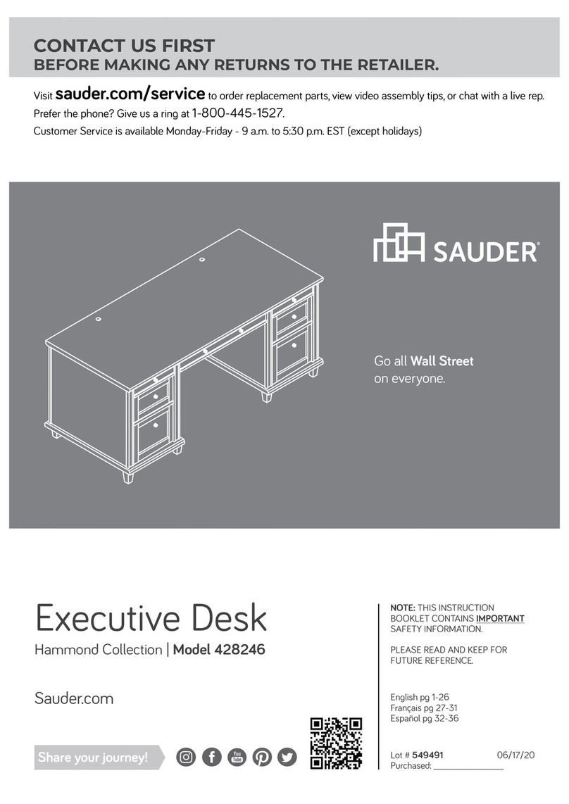
Executive Desk
Edge Water Collection | 419100
Need help? Visit Sauder.com to view video assembly tips or chat with a live rep.
Prefer the phone? Call 1-800-523-3987.
Share your journey!
sauder.com
Get executive
with this decision.
åWhile not all parts are labeled, some of the parts will have a label or an inked letter on the edge
to help distinguish similar parts from each other. Use this part identification to help identify similar parts.
A RIGHT END (1)
B LEFT END (1)
C RIGHT UPRIGHT (1)
D LEFT UPRIGHT (1)
E TOP (1)
F MODESTY PANEL (1)
G BACK (2)
H BRACE (2)
I FRONT LEG (4)
J REAR LEG (4)
K KEYBOARD FRONT (1)
L KEYBOARD BACK (1)
M KEYBOARD SIDE (2)
N KEYBOARD SHELF (1)
O LARGE DRAWER FRONT (2)
S SMALL DRAWER FRONT (2)
V MODESTY PANEL MOLDING (1)
W MOLDING (4)
X TOP MOLDING (2)
Y FOOT (8)
D241 LARGE DRAWER BOX FRONT (4)
D242 SMALL DRAWER BOX FRONT (4)
D253 LARGE DRAWER SIDE (4)
D270 SMALL DRAWER SIDE (4)
D717 DRAWER BOTTOM (4)
Table of Contents Assembly Tools Required
2-3
4-5
6-28
29-32
33-36
37-38
39
Part Identification
Hardware Identification
Assembly Steps
Français
Español
Safety
Warranty
Hammer
Not actual size
No. 2 Phillips Screwdriver
Tip Shown Actual Size
Part Identification
419100 www.sauder.com/servicesPage 2
Part Identification
A
B
C
D
E
F
G
H
I
J
K
L
MN
O
S
W
X
J
J
J
S
O
M
W
W
W
X
I
I
I
Y
Y
Y
Y
Y
Y
Y
Y
V
419100www.sauder.com/services Page 3
G
H
D242
D270 D717
D717
D717
D270
D270
D270
D242
D253
D253
D241
D241
D241
D241
D253
D253
D242
D242
D717
Hardware Identification
åScrews are shown actual size. You may receive extra hardware with your unit.
FILE GLIDE - 4
4BFF EXTENSION SLIDE - 4
EE EXTENSION RAIL - 4
(EXTENSION SET SHOWN SEPARATED)
RIGHT DRAWER SLIDE - 1
CC LEFT DRAWER SLIDE - 1
DD
LEFT CABINET RAIL - 1
BB
RIGHT CABINET RAIL - 1
AA
10F TWIST-LOCK®
FASTENER - 14
HIDDEN CAM - 40
1F
CAM SCREW - 40
8F ANGLE BRACKET - 4
5G
GROMMET - 1
7P GROMMET
CAP - 1
8P
KEYBOARD
HINGE - 2
12H
RAIL BRACKET - 4
18G
419100 www.sauder.com/servicesPage 4
29M BUMPER
CARD - 1
40CA CABINET RIGHT - 2 40CB CABINET LEFT - 2 40CC DRAWER RIGHT - 2 40CD DRAWER LEFT - 2
17K KNOB - 6
Hardware Identification
åScrews are shown actual size. You may receive extra hardware with your unit.
BLACK 1-7/8" FLAT HEAD SCREW - 6
2S
BLACK 1-1/4" FLAT HEAD SCREW - 40
7S
SILVER 1-1/8" FLAT HEAD SCREW - 4
10S
BLACK 1-1-8" PAN HEAD SCREW - 7
9S
BLACK 1-1/8" MACHINE SCREW - 4
21S18S BROWN 1" FLAT HEAD SCREW - 4
BLACK 7/8" LARGE HEAD SCREW - 12
17S
BLACK 7/8" MACHINE SCREW - 2
37S
SILVER 5/8" FLAT HEAD SCREW - 4
23S
BLACK 9/16" LARGE HEAD SCREW - 16
1S
SILVER 9/16" LARGE HEAD SCREW - 2
54S
GOLD 5/16" FLAT HEAD SCREW - 36
3S
419100www.sauder.com/services Page 5
16S BLACK 1-7/8" PAN HEAD SCREW - 8
Step 1 Look for this icon. It means a
video assembly tip is available at
www.sauder.com/services/tips
å Assemble your unit on a carpeted floor or on the empty
carton to avoid scratching your unit or the floor.
å To begin assembly, push a SAUDER TWIST-LOCK®
FASTENER (10F) into the large holes in the UPRIGHTS (C
and D) and MODESTY PANEL (F).
å NOTE: Do not insert TWIST-LOCK® FASTENERS into the
ENDS (A and B) and BACKS (G).
C
D
10F
F
(6 used)
Do not tighten the TWIST-LOCK® FASTENERS in this step.
419100 www.sauder.com/servicesPage 6
Scan this QR code or go to this address:
http://qr.sauder.com/?ID=1394
to watch a video on how to assemble your unit.
å Push forty HIDDEN CAMS (1F) into the ENDS (A and B),
UPRIGHTS (C and D), BACKS (G), and BRACES (H).
Step 2
Arrow
The arrow in the HIDDEN CAM
must point toward the hole in
the edge of the board.
Hole
Do not tighten the HIDDEN CAMS in this step.
Arrow
1F
Arrow
1F
AB
C
D
G
H
G
H
419100www.sauder.com/services Page 7
(40 used)
Step 3
å Turn forty CAM SCREWS (8F) into the ENDS (A and B),
UPRIGHTS (C and D), and LEGS (I and J).
8F
8F
8F
A
B
CD
I
J
J
J
J
I
I
I
419100 www.sauder.com/servicesPage 8
These holes will not be used
on the FRONT LEGS (I).
(40 used)
å Fasten a FRONT LEG (I) and a REAR LEG (J) to the RIGHT
END (A) and RIGHT UPRIGHT (C). Tighten twelve
HIDDEN CAMS.
å Fasten a FOOT (Y) to each LEG (I and J). Use four BLACK
1-7/8" PAN HEAD SCREWS (16S).
Step 4
A
C
J
J
I
I
Y
Y
Y
Y
12
419100www.sauder.com/services Page 9
These CAM SCREWS
should be here.
These CAM SCREWS
should be here.
Surface with
HIDDEN CAMS
Surface with
HIDDEN CAMS
These surfaces should be even.
Surface with
CAM SCREWS
BLACK 1-7/8" PAN HEAD SCREW
(4 used in this step)
16S
Some assembly
(and snacks) required.
Step 5
å Fasten a FRONT LEG (I) and a REAR LEG (J) to the LEFT
END (B) and LEFT UPRIGHT (D). Tighten twelve
HIDDEN CAMS.
å Fasten a FOOT (Y) to each LEG (I and J). Use four BLACK
1-7/8" PAN HEAD SCREWS (16S).
D
B
J
J
I
I
Y
Y
Y
Y
419100 www.sauder.com/servicesPage 10
These CAM SCREWS
should be here.
These CAM SCREWS
should be here.
These surfaces should be even.
Surface with
HIDDEN CAMS
Surface with
HIDDEN CAMS
Surface with
CAM SCREWS
BLACK 1-7/8" PAN HEAD SCREW
(4 used in this step)
16S
å Separate the EXTENSION SLIDES (FF) from the EXTENSION RAILS (EE)
as shown in the upper diagram below. Be prepared, the parts are greasy.
å Fasten the EXTENSION RAILS (EE) to the ENDS (A and B) and
UPRIGHTS (C and D). Use eight GOLD 5/16" FLAT HEAD SCREWS (3S).
å NOTE: For each EXTENSION RAIL, turn a SCREW into the hole shown in
the enlarged diagram. Then, slide the inner cartridge of the EXTENSION
RAIL out to find the other hole that lines up with the hole in the ENDS and
UPRIGHTS. Turn a SCREW into this hole.
Step 6
419100www.sauder.com/services Page 11
EE
EE
EE
EE
D
C
B
A
EEFF
Push the black lever in and pull the SLIDE from the RAIL.
Open end
Open end
Open end
Open end
GOLD 5/16" FLAT HEAD SCREW
(8 used in this step)
3S
Surface with
HIDDEN CAMS
Surface with
HIDDEN CAMS
Surface with
HIDDEN CAMS
Surface with
HIDDEN CAMS
Step 7
å Fasten the CABINET RIGHTS (40CA) and CABINET
LEFTS (40CB) to the ENDS (A and B) and UPRIGHTS (C
and D). Use eight GOLD 5/16" FLAT HEAD SCREWS (3S)
through holes #1 and #3.
419100 www.sauder.com/servicesPage 12
D
C
B
A
Roller end
Roller end
GOLD 5/16" FLAT HEAD SCREW
(8 used in this step)
3S
1
2
3
4
1
2
34
1
2
3
4
Roller end
Roller end
40CA
40CB
1
2
34
å Fasten four RAIL BRACKETS (18G) to the UPRIGHTS (C and D). Use
eight BLACK 9/16" LARGE HEAD SCREWS (1S).
å Fasten the CABINET RAILS (AA and BB) to the RAIL BRACKETS (18G).
Use four GOLD 5/16" FLAT HEAD SCREWS (3S).
å NOTE: The CABINET RAILS are marked "CABINET RIGHT" and
"CABINET LEFT" for easy identification.
Step 8
419100www.sauder.com/services Page 13
Roller end
Roller end
Surface without
TWIST-LOCK®
FASTENERS
Surface without
TWIST-LOCK®
FASTENERS
18G
BB
AA
D
C
I
IBLACK 9/16" LARGE HEAD SCREW
(8 used for the RAIL BRACKETS)
1S
GOLD 5/16" FLAT HEAD SCREW
(4 used for the CABINET RAILS)
3S
Step 9
å Fasten the MODESTY PANEL MOLDING (V)
to the MODESTY PANEL (F). Use three BLACK
1-1/8" PAN HEAD SCREWS (9S).
å Fasten the MODESTY PANEL (F) to the TOP (E).
Tighten two TWIST-LOCK® FASTENERS.
419100 www.sauder.com/servicesPage 14
Unfinished surface
F
F
E
Surface with
TWIST-LOCK®
FASTENERS
This hole must be here.
V
Curved edge
BLACK 1-1/8" PAN HEAD SCREW
(3 used in this step)
9S
Unfinished surface
Dowel end
How to use the SAUDER TWIST-LOCK®FASTENER
1. Insert the dowel end of the FASTENER into the hole of the
adjoining part.
NOTE: The dowel end of the FASTENER must remain fully
inserted in the hole of the adjoining part while locking the
FASTENER.
2. Tighten the FASTENER with a Phillips screwdriver as tight
as possible.
å Fasten the UPRIGHTS (C and D) to the TOP (E). Tighten four
TWIST-LOCK® FASTENERS.
å Fasten the UPRIGHTS (C and D) to the MODESTY PANEL (F).
Use six BLACK 1-7/8" FLAT HEAD SCREWS (2S).
Step 10
419100www.sauder.com/services Page 15
F
E
C
D
Surface without
TWIST-LOCK®
FASTENERS
Surface with
TWIST-LOCK®
FASTENERS
BLACK 1-7/8" FLAT HEAD SCREW
(6 used in this step)
2S
Step 11
å Insert the dowel end of two TWIST-LOCK® FASTENERS (10F) into the TOP (E) as shown in the enlarged diagram.
å NOTE: If you already pushed TWIST-LOCK® FASTENERS into the large holes in the BACKS (G), pull the FASTENERS back
out of the holes. Pull at the front and back edges, slowly working the FASTENERS out of the holes.
å 1. At an angle, push the long edge with holes in the BACKS (G) onto the CAM SCREWS in the LEGS (J).
å 2. Now, swing in the opposite long edge of the BACKS (G) so the TWIST-LOCK® FASTENER in the TOP (E) pushes into the
large holes in the BACKS. Tighten two TWIST-LOCK® FASTENERS and four HIDDEN CAMS.
å Fasten the BRACES (H) to the UPRIGHTS (C and D). Tighten four HIDDEN CAMS.
419100 www.sauder.com/servicesPage 16
C
D
E
G
H
G
H
10F
J
J
These holes must be here.
Surface
with
HIDDEN
CAMS
These holes must be here.
E
G
Surface with
HIDDEN CAMS
Surface with
HIDDEN CAMS
Surface with
HIDDEN CAMS
1. Push this long
edge over the
CAM SCREW.
2. Swing this
edge in over the
TWIST-LOCK®
FASTENER
å Insert the dowel end of six TWIST-LOCK® FASTENERS (10F) into the TOP (E) as shown in
the enlarged diagram.
å NOTE: If you already pushed TWIST-LOCK® FASTENERS into the large holes in the
ENDS (A and B), pull the FASTENERS back out of the holes. Pull at the front and back
edges, slowly working the FASTENERS out of the holes.
å Push the ENDS (A and B) onto the TWIST-LOCK® FASTENERS in the TOP (E). Now,
tighten the TWIST-LOCK® FASTENERS.
å Fasten the REAR LEGS (J) to the BACKS (G). Tighten four HIDDEN CAMS.
å Fasten the ENDS (A and B) to the BRACES (H). Tighten four HIDDEN CAMS.
Step 12
419100www.sauder.com/services Page 17
A
B
E
G
H
G
H
J
J
Surface
with
HIDDEN
CAMS
Surface without
HIDDEN CAMS
A
E
10F
Step 13
å Fasten the TOP MOLDINGS (X) to the TOP (E). Use four
SILVER 1-1/8" FLAT HEAD SCREWS (10S).
419100 www.sauder.com/servicesPage 18
E
X
X
SILVER 1-1/8" FLAT HEAD SCREW
(4 used in this step)
10S
Finished edge and surface
Don't worry. It isn't
Rome. This can be built
in a day.
å Fasten the MOLDINGS (W) to the BACKS (G). Use four BLACK
1-1/8" PAN HEAD SCREWS (9S).
Step 14
419100www.sauder.com/services Page 19
W
F
G
G
W
Curved edge
Curved edge
Curved edge
BLACK 1-1/8" PAN HEAD SCREW
(4 used in this step)
9S
Step 15
å Fasten four ANGLE BRACKETS (5G) to the BRACES (H). Use four BLACK 9/16"
LARGE HEAD SCREWS (1S).
å NOTE: Be sure the edges of the ANGLE BRACKETS are even with the edges of
the BRACES.
å Fasten two MOLDINGS (W) to the ANGLE BRACKETS (5G). Use four BLACK
9/16" LARGE HEAD SCREWS (1S).
419100 www.sauder.com/servicesPage 20
W
W
Curved edge
H
H
Curved edge
5G
5G
BLACK 9/16" LARGE HEAD SCREW
(8 used in this step)
1S

Other Sauder Indoor Furnishing manuals

Sauder Stockbridge 409128 User manual

Sauder

Sauder Stockbridge 409128 User manual

Sauder WoodTrac 416619 User manual

Sauder

Sauder WoodTrac 416619 User manual
Sauder Shoal Creek 409937 User manual

Sauder

Sauder Shoal Creek 409937 User manual

Sauder WHISKER CAT PYRAMID User manual

Sauder

Sauder WHISKER CAT PYRAMID User manual

Sauder Shoal Creek 420272 User manual

Sauder

Sauder Shoal Creek 420272 User manual

Sauder 430083 User manual

Sauder

Sauder 430083 User manual
Sauder 418269 User manual

Sauder

Sauder 418269 User manual

Sauder 402159 User manual

Sauder

Sauder 402159 User manual

Sauder Boulevard Cafe 429410 User manual

Sauder

Sauder Boulevard Cafe 429410 User manual

Sauder Steel River Series User manual

Sauder

Sauder Steel River Series User manual

Sauder New Grange User manual

Sauder

Sauder New Grange User manual

Sauder Manhattan Gate 429251 User manual

Sauder

Sauder Manhattan Gate 429251 User manual

Sauder Steel River 423976 User manual

Sauder

Sauder Steel River 423976 User manual

Sauder Office Port Series User manual

Sauder

Sauder Office Port Series User manual

Sauder 422293 User manual

Sauder

Sauder 422293 User manual

Sauder 413043 User manual

Sauder

Sauder 413043 User manual

Sauder Portage Park 426294 User manual

Sauder

Sauder Portage Park 426294 User manual

Sauder Graham Hill 422811 User manual

Sauder

Sauder Graham Hill 422811 User manual

Sauder Transit 414417 User manual

Sauder

Sauder Transit 414417 User manual

Sauder Nova Loft 423720 User manual

Sauder

Sauder Nova Loft 423720 User manual

Sauder Parklane Series User manual

Sauder

Sauder Parklane Series User manual

Sauder Shoal Creek Series User manual

Sauder

Sauder Shoal Creek Series User manual

Sauder 433242 User manual

Sauder

Sauder 433242 User manual

Sauder Costa 422983 User manual

Sauder

Sauder Costa 422983 User manual

Popular Indoor Furnishing manuals by other brands

Ergo PrimeCables Cab-PC-08211 installation guide

Ergo

Ergo PrimeCables Cab-PC-08211 installation guide

Mocka Arlo Entertainment Unit Assembly instructions

Mocka

Mocka Arlo Entertainment Unit Assembly instructions

Night & Day Furniture Sesame Headboard Assembly instructions

Night & Day Furniture

Night & Day Furniture Sesame Headboard Assembly instructions

Morris and Alexander BR-A2 Fitting & user instructions

Morris and Alexander

Morris and Alexander BR-A2 Fitting & user instructions

Kohler K-3082 Homeowner's guide

Kohler

Kohler K-3082 Homeowner's guide

Amart Furniture TULUM 72537 Assembly instruction

Amart Furniture

Amart Furniture TULUM 72537 Assembly instruction

Forte RICCIANO RCQR721B Assembling Instruction

Forte

Forte RICCIANO RCQR721B Assembling Instruction

Vogue U200 Assembly instructions

Vogue

Vogue U200 Assembly instructions

U-Line H-10142 quick start guide

U-Line

U-Line H-10142 quick start guide

JWA RAFAELA 69420 Assembly instruction

JWA

JWA RAFAELA 69420 Assembly instruction

JWA Leeds 68157 Assembly instruction

JWA

JWA Leeds 68157 Assembly instruction

Bouclair 9397387 Assembly instructions

Bouclair

Bouclair 9397387 Assembly instructions

Techni Sport RTA-TS200 Assembly instructions

Techni Sport

Techni Sport RTA-TS200 Assembly instructions

Mocka Sonata Bed Assembly instructions

Mocka

Mocka Sonata Bed Assembly instructions

adapt-r Premium PRO Installation and user guide

adapt-r

adapt-r Premium PRO Installation and user guide

Whalen WSMTB63-W manual

Whalen

Whalen WSMTB63-W manual

Home affaire 683897 Assembly instructions

Home affaire

Home affaire 683897 Assembly instructions

Amart Furniture VIKA 64084 Assembly instruction

Amart Furniture

Amart Furniture VIKA 64084 Assembly instruction

manuals.online logo
manuals.online logoBrands
  • About & Mission
  • Contact us
  • Privacy Policy
  • Terms and Conditions

Copyright 2025 Manuals.Online. All Rights Reserved.