manuals.online logo
Brands
  1. Home
  2. •
  3. Brands
  4. •
  5. Sauder
  6. •
  7. Indoor Furnishing
  8. •
  9. Sauder Shoal Creek 408924 User manual

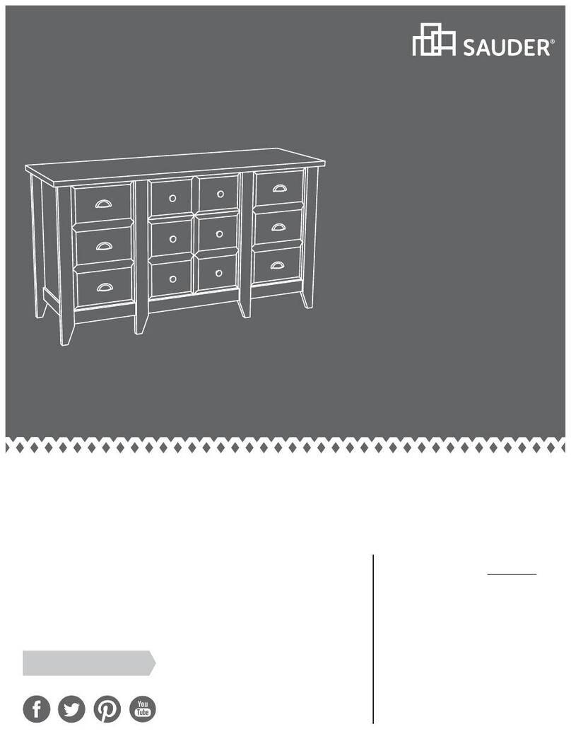
Sauder Shoal Creek 408924 User manual

NOTE: THIS INSTRUCTION
BOOKLET CONTAINS IMPORTANT
SAFETY INFORMATION.
PLEASE READ AND KEEP FOR
FUTURE REFERENCE.
Enlish p 1-25
Français p 26-28
Español p 29-32
Lot # 397206 10/11/16
Purchased: __________________
Be sure to ive us a rin before
makin any returns. 1-800-523-3987
Lateral File
Shoal Creek Collection | Model 408924
Need help? Visit Sauder.com to view video assembly tips or chat with a live rep.
Prefer the phone? Call 1-800-523-3987.
Share your journey!
sauder.com
Get all organized
and stu.
Table of Contents Assembly Tools Required
2-3
4
5-25
26-28
29-32
33-34
35
Part Identification
Hardware Identification
Assembly Steps
Français
Español
Safety
Warranty
Hammer
Not actual size
No. 2 Phillips Screwdriver
Tip Shown Actual Size
Skip the power trip.
This time.
408924 www.sauder.com/servicesPae 2
Part Identification
åWhile not all parts are labeled, some of the parts will have a label or an inked letter on the ede
to help distinuish similar parts from each other. Use this part identification to help identify similar parts.
A RIGHT END (1)
B LEFT END (1)
C2 TOP (1)
D BOTTOM (1)
E SHELF (1)
F BACK (1)
G DOOR (2)
H RIGHT FRONT/LEFT REAR LEG (2)
I LEFT FRONT/RIGHT REAR LEG (2)
J DRAWER FRONT (1)
K DRAWER BOX FRONT (1)
P END MOLDING (2)
D61 DRAWER BACK (1)
D87 RIGHT DRAWER SIDE (1)
D88 LEFT DRAWER SIDE (1)
D729 DRAWER BOTTOM (1)
M63 DRAWER BRACE (1)
Part Identification Now you know
our ABCs.
408924www.sauder.com/services Pae 3
J
K
D61
D87
D88
D729
A
B
C2
D
E
F
G
H
I
P
P
H
I
G
M63
Hardware Identification
åScrews are shown actual size. You may receive extra hardware with your unit.
408924 www.sauder.com/servicesPae 4
BLACK 1-1/8" PAN HEAD SCREW - 4
GG
SILVER 3/4" MACHINE SCREW - 4
HH
SILVER 1-1/4" MACHINE SCREW - 4
FF
BROWN 7/16" LARGE HEAD SCREW - 4
KK
GOLD 5/16" FLAT HEAD SCREW - 8
LL
SILVER 5/8" FLAT HEAD SCREW - 8
II
BLACK 9/16" FLAT HEAD SCREW - 6
JJ
HIDDEN
CAM - 31
1F PULL - 4
Z
CAM
SCREW - 13
8F
SLIDE
CAM - 2
EECC HINGE
SPACER - 4
CAM
DOWEL - 18
2F
(EXTENSION SET SHOWN SEPARATED)
QEXTENSION
RAIL - 2 REXTENSION
SLIDE - 2 FILE ROD - 2
TFILE BAR - 2
U
BUMPER
CARD - 1
OO
FILE GLIDE - 2
6B
FILE
BRACKET - 1
12B
AA HINGE - 4
30S BLACK 1-9/16" FLAT HEAD SCREW - 5
DD FILE
BRACKET - 1
Step 1 Look for this icon. It means a
video assembly tip is available at
www.sauder.com/services/tips
å Assemble your unit on a carpeted floor or on the empty
carton to avoid scratchin your unit or the floor.
å Push thirty-one HIDDEN CAMS (1F) into the ENDS (A
and B), BOTTOM (D), SHELF (E), BACK (F), and DRAWER
BRACE (M63). Then, insert eihteen CAM DOWELS (2F)
into the HIDDEN CAMS except the lon edes of the
ENDS (A and B) and DRAWER BRACE (M63).
408924www.sauder.com/services Pae 5
Do not insert
CAM DOWELS
into these edes.
A
B
D
E
F
M63
Arrow
The arrow in the HIDDEN
CAM must point toward the
hole in the ede of the board.
Hole
(31 used)
(18 used)
Arrow
1F
2F
Do not tihten the HIDDEN CAMS in this step.
Insert the metal end of the CAM
DOWEL into the HIDDEN CAM.
Arrow
Do not insert a
CAM DOWEL
into this part.
Scan this QR code or go to this address:
http://qr.sauder.com/?ID=1701
to watch a video on how to assemble your unit.
Step 2
å Turn thirteen CAM SCREWS (8F) into the LEGS (H and I)
and DRAWER BOX FRONT (K).
408924 www.sauder.com/servicesPae 6
H
I
H
I
8F
K
(13 used)
Remember:
Rihty tihty.
Lefty loosey.
å Fasten one of the LEGS (H and I) to the ENDS (A and B).
Tihten six HIDDEN CAMS.
Step 3
408924www.sauder.com/services Pae 7
A
B
H
I
Curved ede
Curved ede
Surface with
HIDDEN CAMS
Ede with CAM DOWELS
1
2
Surface with
HIDDEN CAMS
Step 4
å Turn six BLACK 9/16" FLAT HEAD SCREWS (JJ) into the
ENDS (A and B) until the shoulders of the SCREWS rest
on the surfaces of the ENDS.
å NOTE: Do not overtihten the SCREWS.
å Now, slide the END MOLDINGS (P) onto the ENDS (A
and B). To do this, line up the rooves in the MOLDINGS
over the heads of the SCREWS in the ENDS. Usin your
hands, apply pressure on the MOLDINGS as you uide
the MOLDINGS onto the ENDS.
å NOTE: If the MOLDINGS come up o of the SCREWS,
remove them and slide them on aain.
408924 www.sauder.com/servicesPae 8
Surface without
HIDDEN CAMS
Surface without
HIDDEN CAMS
A
B
P
P
Shoulder
BLACK 9/16" FLAT HEAD SCREW
(6 used in this step)
JJ
These edes
should be even.
These edes
should be even.
Apply pressure with your hands as
you uide the MOLDINGS over the
SCREWS and onto the ENDS.
å Fasten the remainin LEGS (H and I) to the ENDS (A
and B). Tihten six HIDDEN CAMS.
Step 5
408924www.sauder.com/services Pae 9
A
B
H
I
Curved ede
Curved ede
Surface with
HIDDEN CAMS
Surface with
HIDDEN CAMS
Step 6
å Separate the EXTENSION SLIDES (R) from the
EXTENSION RAILS (Q) as shown in the upper diaram
below. Be prepared, the parts are reasy.
å Fasten the EXTENSION RAILS (Q) to the ENDS (A and B).
Use four GOLD 5/16" FLAT HEAD SCREWS (LL).
å NOTE: For each EXTENSION RAIL, turn a SCREW into the
hole shown in the enlared diaram. Then, slide the inner
cartride of the EXTENSION RAIL out to find the other
hole that lines up with the hole in the END. Turn a SCREW
into this hole.
408924 www.sauder.com/servicesPae 10
A
B
Q
Q
Q
R
GOLD 5/16" FLAT HEAD SCREW
(4 used in this step)
LL
Open end
Open end
Hole
Push the black lever in and pull the SLIDE from the RAIL.
å Fasten the SHELF (E) to the BACK (F). Tihten two
HIDDEN CAMS.
Step 7
408924www.sauder.com/services Pae 11
E
F
Surface with
HIDDEN CAMS
Ede with HIDDEN CAMS
Finished ede
Start Tighten
Arrow
Minimum
190 derees
Caution
Risk of damae or
injury. HIDDEN CAMS
must be completely
tihtened. HIDDEN
CAMS that are not
completely tihtened
may loosen, and parts
may separate. To
completely tihten:
Arrow
Maximum
210 derees
Surface with
HIDDEN CAMS
Step 8
å Fasten the BOTTOM (D) to the BACK (F). Tihten two
HIDDEN CAMS.
408924 www.sauder.com/servicesPae 12
D
F
Finished ede
Arrow
Minimum
190 derees
Maximum
210 derees
Surface with
HIDDEN CAMS
å Fasten the ENDS (A and B) to the BOTTOM (D) and
SHELF (E). Tihten eiht HIDDEN CAMS.
Step 9
408924www.sauder.com/services Pae 13
A
B
D
E
Arrow
Minimum
190 derees
Maximum
210 derees
Surface with HIDDEN CAMS
Surface without
HIDDEN CAMS
Step 10
å Carefully stand your unit upriht.
å Fasten the TOP (C2) to the ENDS (A and B) and BACK (F).
Tihten six HIDDEN CAMS.
408924 www.sauder.com/servicesPae 14
A
B
C2
F
Arrow
Minimum
190 derees
Maximum
210 derees
Pro Tip: Lift with your
les. And, you know,
your arms.
Meet Part (C2). This component has
been enineered to be lihter, stroner,
faster… well ok. Not technically faster.
But definitely makes for a sturdier
Lateral File that’s easier to assemble
and friendlier to the environment.
å Fasten four HINGES (AA) and four HINGE SPACERS (CC)
to the DOORS (G). Use eiht SILVER 5/8" FLAT
HEAD SCREWS (II).
Step 11
408924www.sauder.com/services Pae 15
G
AA
CC
AA
CC
G
AA
CC
AA
CC
SILVER 5/8" FLAT HEAD SCREW
(8 used in this step)
II
Step 12
å Before fastenin the DOOR to your unit, be sure the
mountin screw is aainst the stops as shown in the
diaram. If it isn't, loosen the mountin screw to slide it
aainst the stops. Then tihten the mountin screw.
å Fasten one of the DOORS (G) to the LEFT END (B). Use
the screws in the HINGES.
å Peel the BUMPER from the BUMPER CARD (OO). Stick
a BUMPER on the DOOR where it comes in contact with
the SHELF (E).
å Fasten a PULL (Z) to the DOOR (G). Use two SILVER
3/4" MACHINE SCREWS (HH).
å Repeat this step for the other DOOR (G).
408924 www.sauder.com/servicesPae 16
B
E
G
(2 used)
SILVER 3/4" MACHINE SCREW
(4 used for the PULLS)
HH
Mountin
screw
Stop
Hine
Z
OO
Want options? Customize
your item with add-on
hardware kits available
on sauder.com.
å Refer to the enlared diaram to identify the parts on the
HINGES and HINGE BRACKETS.
å The DOORS may need some adjustments. Follow the text
below to make needed adjustments. DOOR ADJUSTMENTS:
å To adjust the DOORS from side to side (horizontal), turn the
adjustin screw in or out.
å To adjust the DOORS up and down (vertical), loosen both
screws that fasten the HINGE BRACKETS to the END. Move the
DOORS up or down to the desired location. Tihten the screws
after makin adjustments.
å To adjust the DOORS in or out (depth), loosen the mountin
screw one turn and move the DOORS in or out, as needed.
Tihten the mountin screw after makin adjustments.
Step 13
408924www.sauder.com/services Pae 17
Adjustin screw (horizontal)
Mountin screw (depth)
(vertical adjustment)
Step 14
408924 www.sauder.com/servicesPae 18
å Insert the DRAWER SIDES (D87 and D88) at an angle
into the slot at each end of the DRAWER BOX FRONT (K).
å Slide the DRAWER BOTTOM (D729) into the grooves
in the DRAWER SIDES (D87 and D88) and DRAWER
BOX FRONT (K).
å Fasten the DRAWER BRACE (M63) to the DRAWER
BOX FRONT (K). Tighten one HIDDEN CAM. å Fasten the DRAWER BACK (D61) to the DRAWER
SIDES (D87 and D88) and DRAWER BRACE (M63). Use
five BLACK 1-9/16" FLAT HEAD SCREWS. (30S).
12
34
Be sure the DRAWER
BOTTOM inserts into the
DRAWER FRONT roove.
With the palm of your hand,
tap the DRAWER BOTTOM
down into the roove.
Groove
Arrow
Maximum
210 derees
Minimum
190 derees
K
K
K
VIEW THE T-LOCK BOX VIDEO
D88
D87
D88
D729
D87
D87
D88
D61
Unfinished
surface
Be sure the
DRAWER
BOTTOM
inserts into
the DRAWER
BACK roove.
30S
Start each screw a few turns before
completely tihtenin any of them.
BLACK 1-9/16" FLAT HEAD SCREW
(5 used in this step)
The tabs should insert freely
into the slots. Gently tilt the
DRAWER SIDES side to side
until the tabs slip into the slots.
Surface with
HIDDEN CAM
M63
M63
å Fasten the DRAWER FRONT (J) to the DRAWER
BOX FRONT (K). Use four BLACK 1-1/8" PAN
HEAD SCREWS (GG).
Step 15
408924www.sauder.com/services Pae 19
J
K
BLACK 1-1/8" PAN HEAD SCREW
(4 used in this step)
GG
Step 16
å Insert the SLIDE CAMS (EE) into the lare holes in the
DRAWER SIDES (D87 and D88).
å Fasten the EXTENSION SLIDES (R) to the DRAWER
SIDES (D87 and D88). Use four GOLD 5/16" FLAT HEAD
SCREWS (LL) throuh holes #1 and #4.
å NOTE: The screw head in the CAM must be visible
throuh the slotted hole in the SLIDE.
408924 www.sauder.com/servicesPae 20
R
R
D87
D88
Open end
Open end
Screw head - turn CAM to line up holes in
the SLIDES with holes in DRAWER SIDES
GOLD 5/16" FLAT HEAD SCREW
(4 used in this step)
LL
1
2
3
4
1
2
3
4
EE
EE

Other Sauder Indoor Furnishing manuals

Sauder Storage Cabinet 419496 User manual

Sauder

Sauder Storage Cabinet 419496 User manual

Sauder Anywhere Dakota Pass 418231 User manual

Sauder

Sauder Anywhere Dakota Pass 418231 User manual

Sauder 414254 User manual

Sauder

Sauder 414254 User manual

Sauder Pinwheel 421885 User manual

Sauder

Sauder Pinwheel 421885 User manual

Sauder Registry Row Series User manual

Sauder

Sauder Registry Row Series User manual

Sauder 419119 User manual

Sauder

Sauder 419119 User manual

Sauder 431238 User manual

Sauder

Sauder 431238 User manual

Sauder Boulevard Cafe 420645 User manual

Sauder

Sauder Boulevard Cafe 420645 User manual

Sauder Manhattan Gate 429257 User manual
Sauder

Sauder Manhattan Gate 429257 User manual

Sauder Via 419642 User manual

Sauder

Sauder Via 419642 User manual

Sauder Portage Park 427478 User manual

Sauder

Sauder Portage Park 427478 User manual

Sauder 413322 User manual

Sauder

Sauder 413322 User manual

Sauder Carson Forge Technology Pier 412923 User manual

Sauder

Sauder Carson Forge Technology Pier 412923 User manual

Sauder 2-Door Wardrobe/Armoire Clothes Storage Cabinet With Hanger Rod & Shelves... User manual

Sauder

Sauder 2-Door Wardrobe/Armoire Clothes Storage Cabinet With Hanger Rod & Shelves... User manual

Sauder worksense MASON PEAK 427807 User manual

Sauder

Sauder worksense MASON PEAK 427807 User manual

Sauder 427350 User manual

Sauder

Sauder 427350 User manual

Sauder Craft Armoire User manual

Sauder

Sauder Craft Armoire User manual

Sauder Palladia Collection Credenza 412079 User manual

Sauder

Sauder Palladia Collection Credenza 412079 User manual

Sauder 430237 User manual

Sauder

Sauder 430237 User manual

Sauder 402159 User manual

Sauder

Sauder 402159 User manual

Sauder OFFICE WORKS AFFIRM Hudson Elm 427429 User manual

Sauder

Sauder OFFICE WORKS AFFIRM Hudson Elm 427429 User manual

Sauder Harbor View 8070-297 User manual

Sauder

Sauder Harbor View 8070-297 User manual

Sauder Carson Forge 416969 User manual

Sauder

Sauder Carson Forge 416969 User manual

Sauder Cottage Road 427307 User manual

Sauder

Sauder Cottage Road 427307 User manual

Popular Indoor Furnishing manuals by other brands

Alphason Houston AOC4201A-L-BK quick start guide

Alphason

Alphason Houston AOC4201A-L-BK quick start guide

Dorel Asia DA6275R-P Instruction booklet

Dorel Asia

Dorel Asia DA6275R-P Instruction booklet

Santalucia Mobili HOMY Night quick start guide

Santalucia Mobili

Santalucia Mobili HOMY Night quick start guide

RH Focus user guide

RH

RH Focus user guide

Glacier G42SB Assembly manual

Glacier

Glacier G42SB Assembly manual

Livarno Living 283347 Assembly instruction

Livarno Living

Livarno Living 283347 Assembly instruction

Ilva 1051590 Assembly instruction

Ilva

Ilva 1051590 Assembly instruction

Bassett INSPIRED KAI BP-KAI30 Assembly instructions

Bassett

Bassett INSPIRED KAI BP-KAI30 Assembly instructions

Auping 455 user manual

Auping

Auping 455 user manual

MSI MAG CH110 quick start guide

MSI

MSI MAG CH110 quick start guide

Forte Bohol BHLV631 Assembling Instruction

Forte

Forte Bohol BHLV631 Assembling Instruction

FRITZ HANSEN LUNE Assembly instruction

FRITZ HANSEN

FRITZ HANSEN LUNE Assembly instruction

Multay Seville 2 Door Wardrobe KD SVB09 Assembly instruction

Multay

Multay Seville 2 Door Wardrobe KD SVB09 Assembly instruction

IMG Group Scandi Assembly instructions

IMG Group

IMG Group Scandi Assembly instructions

Frank Olsen INTELLIGENT LAMP TABLE quick start guide

Frank Olsen

Frank Olsen INTELLIGENT LAMP TABLE quick start guide

Serta Motion Essentials V King owner's manual

Serta

Serta Motion Essentials V King owner's manual

Coaster 204691Q Assembly instruction

Coaster

Coaster 204691Q Assembly instruction

Mocka Marlow Bedside Table Assembly instructions

Mocka

Mocka Marlow Bedside Table Assembly instructions

manuals.online logo
manuals.online logoBrands
  • About & Mission
  • Contact us
  • Privacy Policy
  • Terms and Conditions

Copyright 2025 Manuals.Online. All Rights Reserved.