manuals.online logo
Brands
  1. Home
  2. •
  3. Brands
  4. •
  5. Sauder
  6. •
  7. Indoor Furnishing
  8. •
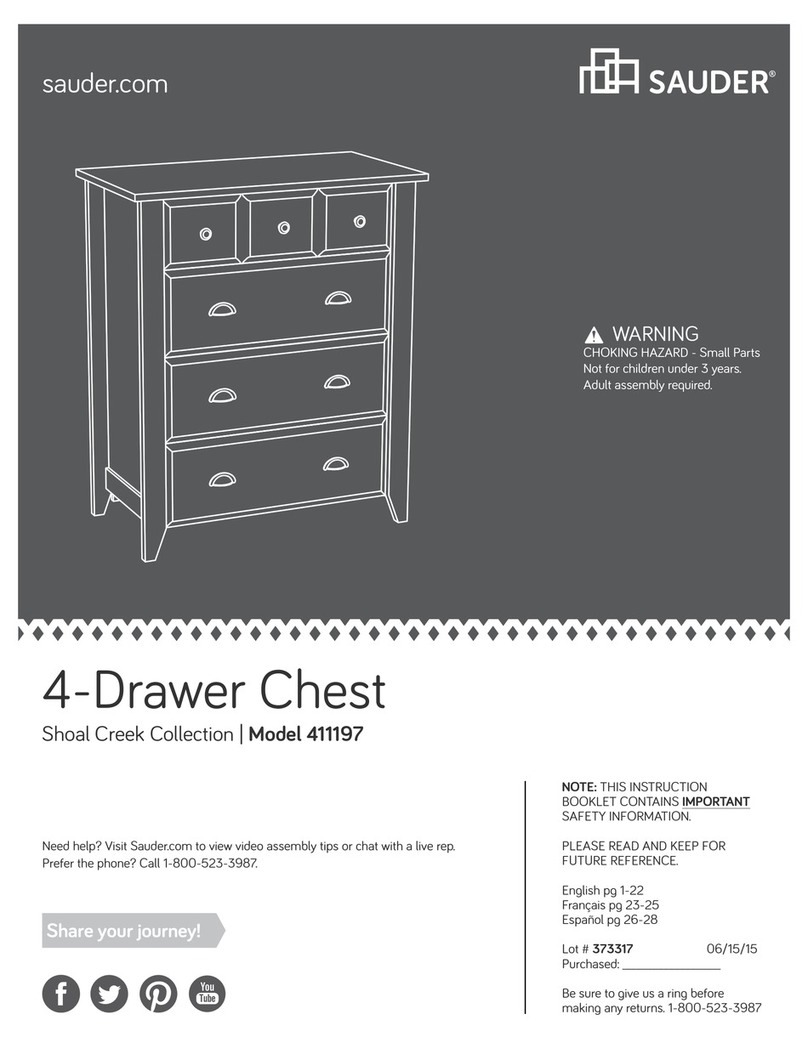
  9. Sauder Harbor View 414942 User manual

Sauder Harbor View 414942 User manual

PLEASE CONTACT US
BEFORE RETURNING
YOUR UNIT TO THE STORE
1-800-523-3987
www.sauder.com
Made in the USA
Archbold, OH
NOTE: THIS INSTRUCTION BOOKLET CONTAINS
IMPORTANT SAFETY INFORMATION.
PLEASE READ AND KEEP FOR FUTURE REFERENCE.
English.................... Page 1-26
Français...............Pages 27-29
Espanol.............Páginas 30-32
Lot #: 353496 07 / 19 / 13
Date Purchased: ____________________
414942
Dresser
Harbor View Collection
ADULT ASSEMBLY REQUIRED
TABLE OF CONTENTS
Part Identification...................2-3
Hardware Identification .............4
Assembly Steps....................5-26
Français..............................27-29
Espanol...............................30-32
Safety .................................33-34
Warranty...................................35
ASSEMBLY TOOLS REQUIRED
Hammer
No. 2 Phillips Screwdriver
Tip Shown Actual Size
A RIGHT END 1
B LEFT END 1
C RIGHT UPRIGHT 1
D LEFT UPRIGHT 1
E UPRIGHT 1
F TOP 1
G BOTTOM 1
H FRONT BRACE 1
I BACK 1
J CENTER BACK 2
K RIGHT DOOR 1
L LEFT DOOR 1
M RIGHT DRAWER FRONT 1
N LEFT DRAWER FRONT 1
O UPPER DRAWER FRONT 1
P LOWER DRAWER FRONT 1
Q FRONT MOLDING 1
R RIGHT MOLDING 1
S LEFT MOLDING 1
T BOTTOM MOLDING 1
U SKIRT 1
V BRACE MOLDING 1
W DRAWER BRACE 4
X BACK BRACE 1
Y FOOT 2
D12 UPPER RIGHT DRAWER SIDE 1
D13 UPPER LEFT DRAWER SIDE 1
D24 RIGHT DRAWER SIDE 2
D25 LEFT DRAWER SIDE 2
D30 LOWER RIGHT DRAWER SIDE 1
D31 LOWER LEFT DRAWER SIDE 1
D166 UPPER DRAWER BACK 1
D167 LOWER DRAWER BACK 1
D170 DRAWER BACK 2
D945 DRAWER BOTTOM 2
D974 LOWER DRAWER BOTTOM 2
Page 2 www.sauder.com/services 414942
PART IDENTIFICATION: While not all parts are labeled, some of the parts will have a label or an inked
letter on the edge to help distinguish similar parts from each other. Use this PART IDENTIFICATION to help
identify similar parts.
PART IDENTIFICATION
Page 3
www.sauder.com/services414942
A
B
C
D
E
F
G
H
I
J
K
L
M
N
O
P
Q
S
T
U
V
X
YD945
D945
D974
D974
D166
D167
D170 D24
D25
D170 D24
D25
D12
D13
W
W
W
W
Y
D30
D31
R
J
HARDWARE IDENTIFICATION
Screws are shown actual size. You may receive extra hardware with your unit.
Page 4 www.sauder.com/services 414942
5L WARNING LABEL - 1
(Refer to the last step for proper
location and application)
WARNING
!
Serious or fatal crushing injuries can
occur from furniture tip-over. To help
prevent tip-over:
• Place heaviest items in the lowest drawers.
• Unless specifically designed to accommodate, do not
set TVs or other heavy objects on top of this product.
• Never allow children to climb or hang on drawers,
doors, or shelves.
• Never open more than one drawer at a time.
• If equipped with a drawer interlock system, do not
defeat or remove it.
Use of tip-over restraints may only reduce,
but not eliminate, the risk of tip-over.
This is a permanent label. Do not attempt to remove!
04/10 332296
35GA CABINET RIGHT - 4 35GB CABINET LEFT - 4 35GC DRAWER RIGHT - 4 35GD DRAWER LEFT - 4
BLACK 1-1/8" PAN HEAD SCREW - 6
9S
SAFETY BRACKET - 1
1G
BLACK 9/16" LARGE HEAD SCREW - 1
1S
BLACK 1/2" FLAT HEAD SCREW - 8
11S
SILVER 3/4" MACHINE SCREW - 8
20S BLACK 1-5/8" PAN HEAD SCREW - 8
27S
BLACK 1-7/8" FLAT HEAD SCREW - 10
2S
TWIST-LOCK®
FASTENER - 18
10F
FOOT SCREW - 2
23F
MOLDING
CONNECTOR - 2
16F
GOLD 5/16" FLAT HEAD SCREW - 32
3S
METAL PIN - 4
1R
SLIDE CAM - 8
10A
NAIL - 49
1N
13H HINGE - 4 KNOB - 6
5K PULL - 4
98K
FELT DISC CARD - 1
1M
BLACK 1-9/16" FLAT HEAD SCREW - 20
30S
CAM DOWEL - 8
2F
HIDDEN CAM - 8
1F
SILVER 7/8" MACHINE SCREW - 6
42S
BLACK 1-15/16" FLAT HEAD SCREW - 8
4S
Look for this icon. It means a video
assembly tip is available at:
www.sauder.com/services/tips
1
1
S
t
e
p
Assemble your unit on a carpeted floor or on the empty carton to avoid scratching your unit or the floor.
To begin assembly, push a SAUDER TWIST-LOCK® FASTENER (10F) into the large holes in the RIGHT UPRIGHT (C) and LEFT
UPRIGHT (D). Repeat this step for the UPRIGHT (E), BOTTOM (G), and BRACES (H and X).
Page 5
www.sauder.com/services414942
Do not tighten the TWIST-LOCK® FASTENERS in this step.
10F
(18 used)
C
D
2
2
S
t
e
p
Page 6 www.sauder.com/services 414942
Push eight HIDDEN CAMS (1F) into the ENDS (A and B) and DRAWER BRACES (W). Then, insert the metal end of a CAM
DOWEL (2F) into each HIDDEN CAM.
Do not tighten the HIDDEN CAMS in this step.
Arrow
1F
2F
Insert the metal end of the CAM
DOWEL into the HIDDEN CAM.
Arrow
W
W
W
W
B
A
3
3
S
t
e
p
Page 7
www.sauder.com/services414942
Roller end
Fasten a CABINET RIGHT (35GA) to the RIGHT END (A) and a CABINET LEFT (35GB) to the LEFT END (B). Use four GOLD
5/16" FLAT HEAD SCREWS (3S) through holes #1 and #3.
GOLD 5/16” FLAT HEAD SCREW
(4 used in this step)
3S
1
2
3
3
2
1
Roller end
A
B
Surface with holes
Surface with holes
Finished edge
Finished edge
4
4
S
t
e
p
Page 8 www.sauder.com/services 414942
Fasten the CABINET RIGHTS (35GA) to the RIGHT UPRIGHT (C) and UPRIGHT (E) and the CABINET LEFTS (35GB) to
the LEFT UPRIGHT (D) and other surface of the UPRIGHT (E). Use twelve GOLD 5/16" FLAT HEAD SCREWS (3S) through
holes #1 and #3.
GOLD 5/16” FLAT HEAD SCREW
(12 used in this step)
3S
C
D
1
2
3
1
2
3
Surface with
TWIST-LOCK
®
FASTENERS
Surface with
TWIST-LOCK
®
FASTENERS
3
2
1
3
2
1
Finished edge
Finished edge
Roller end
Roller end
E
Surface with
TWIST-LOCK®
FASTENERS
1
2
3
1
2
3
Roller end
Roller end
Finished edge
5
5
S
t
e
p
Page 9
www.sauder.com/services414942
Tap two MOLDING CONNECTORS (16F) into the notches in the MOLDINGS (Q, R, and S).
Flat end
Flat end
16F
16F
Use your hammer to tap the MOLDING CONNECTOR (16F) into the notches in the MOLDINGS.
QR
S
6
6
S
t
e
p
Page 10 www.sauder.com/services 414942
Fasten the UPRIGHTS (C and D) to the BRACES (H and X). Tighten four TWIST-LOCK®FASTENERS.
How to use the SAUDER TWIST-LOCK®FASTENER
1. Insert the dowel end of the FASTENER into the
hole of the adjoining part.
NOTE: The dowel end of the FASTENER must remain
fully inserted in the hole of the adjoining part while
locking the FASTENER.
2. Tighten the FASTENER with a Phillips screwdriver
as tight as possible.
Dowel end
C
D
H
X
Edge with
TWIST-LOCK®
FASTENERS
Surface with
TWIST-LOCK
®
FASTENERS
Surface with
TWIST-LOCK
®
FASTENERS
Finished edge
Surface with
TWIST-LOCK®
FASTENERS
Surface without
TWIST-LOCK®
FASTENERS
Finished edge
The long edge closer
to the TWIST-LOCK®
FASTENERS should be here.
Fasten the BACKS (J) to the UPRIGHTS (C and D). Use eight BLACK 1-15/16" FLAT HEAD SCREWS (4S).
7
7
S
t
e
p
Page 11
www.sauder.com/services414942
C
D
J
J
BLACK 1-15/16" FLAT HEAD SCREW
(8 used in this step)
4S
Insert two METAL PINS (1R) into the BRACES (H and X).
Fasten the LEFT END (B) to the BRACES (H and X). Tighten two TWIST-LOCK®FASTENERS.
NOTE: Be sure the METAL PINS in the BRACES (H and X) insert into the holes in the LEFT END (B).
Fasten the BOTTOM (G) to the LEFT END (B). Tighten two TWIST-LOCK®FASTENERS.
Then, fasten the BOTTOM (G) to the UPRIGHTS (C and D). Use four BLACK 1-7/8" FLAT HEAD SCREWS (2S).
8
8
S
t
e
p
Page 12 www.sauder.com/services 414942
H
X
B
GC
D
1R
Finished edge
Surface with
TWIST-LOCK
®
FASTENERS
BLACK 1-7/8" FLAT HEAD SCREW
(4 used in this step)
2S
This hole
must be here.
Surface with
HIDDEN CAMS
9
9
S
t
e
p
Page 13
www.sauder.com/services414942
H
X
G
A
Insert two METAL PINS (1R) into the BRACES (H and X).
Fasten the RIGHT END (A) to the BOTTOM (G) and BRACES (H and X). Tighten four TWIST-LOCK®FASTENERS.
NOTE: Be sure the METAL PINS in the BRACES (H and X) insert into the holes in the RIGHT END (A).
Surface without
HIDDEN CAMS
Finished edge
1R
10
10
S
t
e
p
Page 14 www.sauder.com/services 414942
H
X
E
Finished edge
Fasten the BRACE MOLDING (V) to the FRONT BRACE (H). Tighten four TWIST-LOCK®FASTENERS.
Fasten the UPRIGHT (E) to the BRACES (H and X). Use two BLACK 1-7/8" FLAT HEAD SCREWS (2S).
BLACK 1-7/8" FLAT HEAD SCREW
(2 used in this step)
2S
V
Surface with
TWIST-LOCK®
FASTENERS
11
11
S
t
e
p
Page 15
www.sauder.com/services414942
S
R
Q
Fasten the MOLDINGS (Q, R, and S) to the TOP (F). Use eight BLACK 1-5/8" PAN HEAD SCREWS (27S).
F
Surface with holes
Rounded edge
BLACK 1-5/8" PAN HEAD SCREW
(8 used in this step)
27S
Fasten the ENDS (A and B) to the MOLDINGS (R and S) on the TOP (F). Tighten four HIDDEN CAMS.
NOTE: Be sure the dowel ends of the TWIST-LOCK®FASTENERS in the UPRIGHT (E) insert into the holes in the TOP (F).
Then, fasten the TOP (F) to the UPRIGHT (E). Tighten two TWIST-LOCK®FASTENERS.
12
12
S
t
e
p
Page 16 www.sauder.com/services 414942
R
S
EF
Surface with
holes
Rounded edge
Caution
Risk of damage or
injury. Hidden Cams
must be completely
tightened. Hidden
Cams that are not
completely tightened
may loosen, and parts
may separate.
To completely tighten:
Start Tighten
Arrow
Arrow
Maximum
210 degrees
Minimum
190 degrees
A
B
13
13
S
t
e
p
Page 17
www.sauder.com/services414942
First, fasten the SKIRT (U) to the BOTTOM MOLDING (T). Use three BLACK 1-7/8" FLAT HEAD SCREWS (2S).
Then, fasten the BOTTOM MOLDING (T) to the BOTTOM (G). Use six BLACK 1-1/8" PAN HEAD SCREWS (9S).
Carefully turn two FOOT SCREWS (23F) a few turns into the BOTTOM MOLDING (T).
Next, turn a FOOT (Y) onto the other end of each FOOT SCREW (23F). Turn the FEET clockwise until the FOOT SCREW is tight in
the BOTTOM MOLDING (T) and each FOOT.
NOTE: Do not overtighten the FOOT SCREWS.
BLACK 1-1/8" PAN HEAD SCREW
(6 used for the BOTTOM MOLDING)
9S
BLACK 1-7/8" FLAT HEAD SCREW
(3 used for the SKIRT)
2S
UT
Flat surface
Rounded edge
T
Unfinished
surface
23F
Y
Y
Rounded edge
U
14
14
S
t
e
p
Page 18 www.sauder.com/services 414942
Carefully turn your unit over onto its front edges. Unfold the BACK (I) and lay it over your unit.
Make equal margins along all four edges of the BACK (I). Push on opposite corners of your unit if needed to make it “square”.
Fasten the BACK (I) to your unit using the NAILS (1N).
NOTE: Be sure to tap NAILS into the holes that line up over the UPRIGHTS (C and D) and BACK BRACE (X).
NOTE: Perforations have been provided for access through the BACK. Carefully cut out the holes needed.
Do not stand the unit upright without the
BACK fastened. The unit may collapse.
Caution
NAIL
(49 used in this step)
1N
These holes must line up over the
UPRIGHTS and BACK BRACE.
I
Cut-out (used for lifting)
15
15
S
t
e
p
Page 19
www.sauder.com/services414942
K
BLACK 1/2” FLAT HEAD SCREW
(8 used for the HINGES)
11S
Fasten two HINGES (13H) to each DOOR (K and L). Use eight BLACK 1/2" FLAT HEAD SCREWS (11S).
13H
13H
L
16
16
S
t
e
p
Page 20 www.sauder.com/services 414942
Carefully stand your unit upright.
NOTE: You may need to loosen the mounting and adjusting screws to slide the hinge part way out of the slot before fastening it to the
END. Retighten the screw before you mount the HINGE to the END.
Fasten the LEFT DOOR (L) to the LEFT END (B). Use the screws in the HINGES. See the next step for adjustments.
Fasten a KNOB (5K) to the LEFT DOOR (L). Use a SILVER 7/8" MACHINE SCREW (42S).
Peel a FELT DISC from the FELT DISC CARD (1M) and stick it on the DOOR where it comes in contact with the LEFT UPRIGHT (D).
Repeat this step for the other door.
Mounting screw (depth)
Adjusting screw (horizontal)
L
B
D
1M
1M
5K
SILVER 7/8" MACHINE SCREW
(2 used for the KNOBS)
42S

Other Sauder Indoor Furnishing manuals

Sauder Trestle 416955 User manual

Sauder

Sauder Trestle 416955 User manual

Sauder Palladia 411830 User manual

Sauder

Sauder Palladia 411830 User manual

Sauder County Line 416977 User manual

Sauder

Sauder County Line 416977 User manual

Sauder Shoal Creek 409714 User manual

Sauder

Sauder Shoal Creek 409714 User manual

Sauder worksense MASON PEAK 427807 User manual

Sauder

Sauder worksense MASON PEAK 427807 User manual

Sauder New Grange 422180 User manual

Sauder

Sauder New Grange 422180 User manual

Sauder Worksense BERGEN CIRCLE 426298 User manual

Sauder

Sauder Worksense BERGEN CIRCLE 426298 User manual

Sauder Cannery Bridge 415910 User manual

Sauder

Sauder Cannery Bridge 415910 User manual

Sauder Credenza Soft Modern 414986 User manual

Sauder

Sauder Credenza Soft Modern 414986 User manual

Sauder Shoal Creek Series User manual

Sauder

Sauder Shoal Creek Series User manual

Sauder Orchard Hills 418650 User manual

Sauder

Sauder Orchard Hills 418650 User manual

Sauder 420850 User manual

Sauder

Sauder 420850 User manual

Sauder 1034-290 User manual

Sauder

Sauder 1034-290 User manual

Sauder Harvest Mill 404963 User manual

Sauder

Sauder Harvest Mill 404963 User manual

Sauder Worksense BERGEN CIRCLE 426906 User manual

Sauder

Sauder Worksense BERGEN CIRCLE 426906 User manual

Sauder Radial 426023 User manual

Sauder

Sauder Radial 426023 User manual

Sauder North Avenue 425190 User manual

Sauder

Sauder North Avenue 425190 User manual

Sauder HomePlus 422428 User manual

Sauder

Sauder HomePlus 422428 User manual

Sauder Embassy Point 414192 User manual

Sauder

Sauder Embassy Point 414192 User manual

Sauder Canal Street 420494 User manual

Sauder

Sauder Canal Street 420494 User manual

Sauder 418213 User manual

Sauder

Sauder 418213 User manual

Sauder 409942 User manual

Sauder

Sauder 409942 User manual

Sauder Manhattan Gate 429254 User manual
Sauder

Sauder Manhattan Gate 429254 User manual

Sauder Lateral File Boulevard Cafe 427345 User manual

Sauder

Sauder Lateral File Boulevard Cafe 427345 User manual

Popular Indoor Furnishing manuals by other brands

Pulaski Furniture A887U-305-1797 Assembly instructions

Pulaski Furniture

Pulaski Furniture A887U-305-1797 Assembly instructions

Gami BOSTON 175 manual

Gami

Gami BOSTON 175 manual

FMD DIEGO 367-001 Assembly instruction

FMD

FMD DIEGO 367-001 Assembly instruction

Crate&Barrel Jenny Lind quick start guide

Crate&Barrel

Crate&Barrel Jenny Lind quick start guide

simplyput SP-ECW10-1-35-W installation instructions

simplyput

simplyput SP-ECW10-1-35-W installation instructions

Sensio Accent SE185700 installation guide

Sensio

Sensio Accent SE185700 installation guide

LIMELIGHT Beds ELOISE 5FT Assembly instructions

LIMELIGHT Beds

LIMELIGHT Beds ELOISE 5FT Assembly instructions

Grizzly T10131 instruction manual

Grizzly

Grizzly T10131 instruction manual

JSI Moto installation instructions

JSI

JSI Moto installation instructions

Koala Timber Bookshelf manual

Koala

Koala Timber Bookshelf manual

RSA Lighting QCT901MH specification

RSA Lighting

RSA Lighting QCT901MH specification

aspenhome Oxford I07-412-WBR Assembly instructions

aspenhome

aspenhome Oxford I07-412-WBR Assembly instructions

DURAVIT XSquare XS 7113 Mounting instructions

DURAVIT

DURAVIT XSquare XS 7113 Mounting instructions

Mocka Alps Bedside Table Assembly instructions

Mocka

Mocka Alps Bedside Table Assembly instructions

Forte JWL1162 Assembling Instruction

Forte

Forte JWL1162 Assembling Instruction

Julian Bowen Limited COX004 Assembly instructions

Julian Bowen Limited

Julian Bowen Limited COX004 Assembly instructions

Convex OUTDOOR ACRYLIC installation guide

Convex

Convex OUTDOOR ACRYLIC installation guide

Royal Catering RCBC-01 user manual

Royal Catering

Royal Catering RCBC-01 user manual

manuals.online logo
manuals.online logoBrands
  • About & Mission
  • Contact us
  • Privacy Policy
  • Terms and Conditions

Copyright 2025 Manuals.Online. All Rights Reserved.