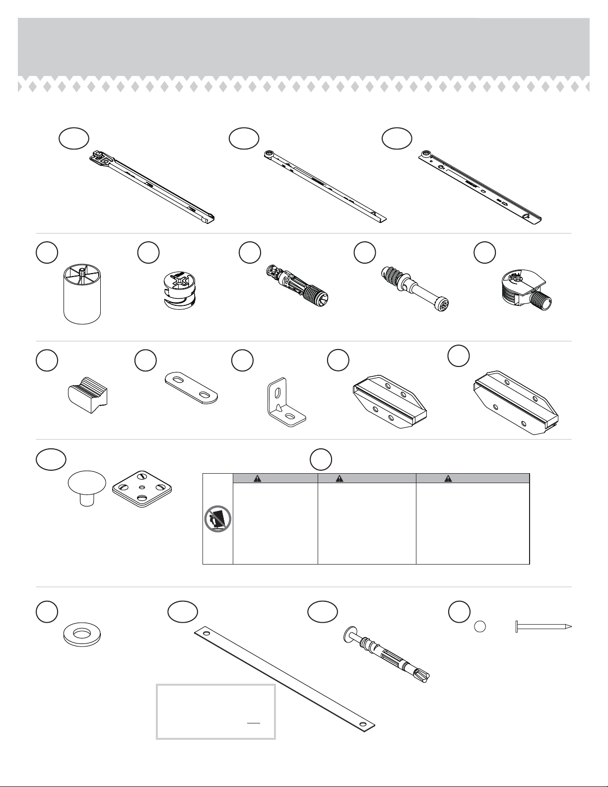
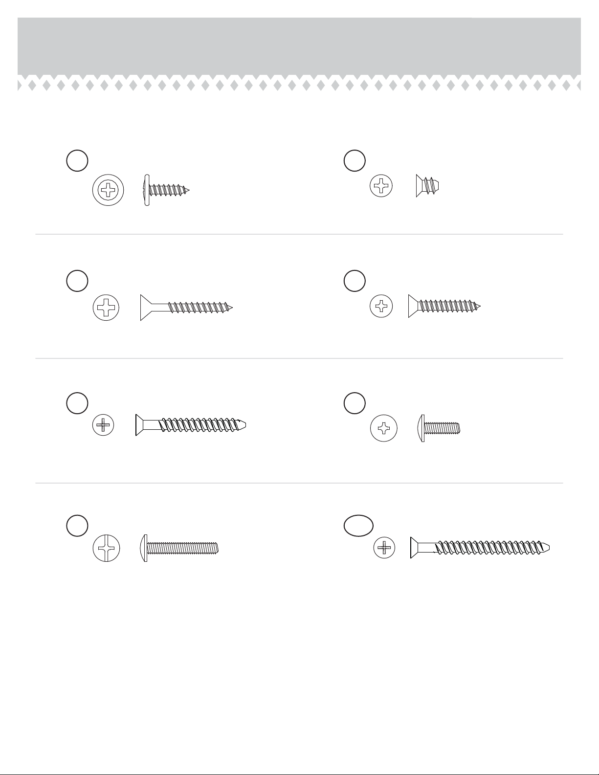
Hardware Identification
åScrews are shown actual size. You may receive extra hardware with your unit.
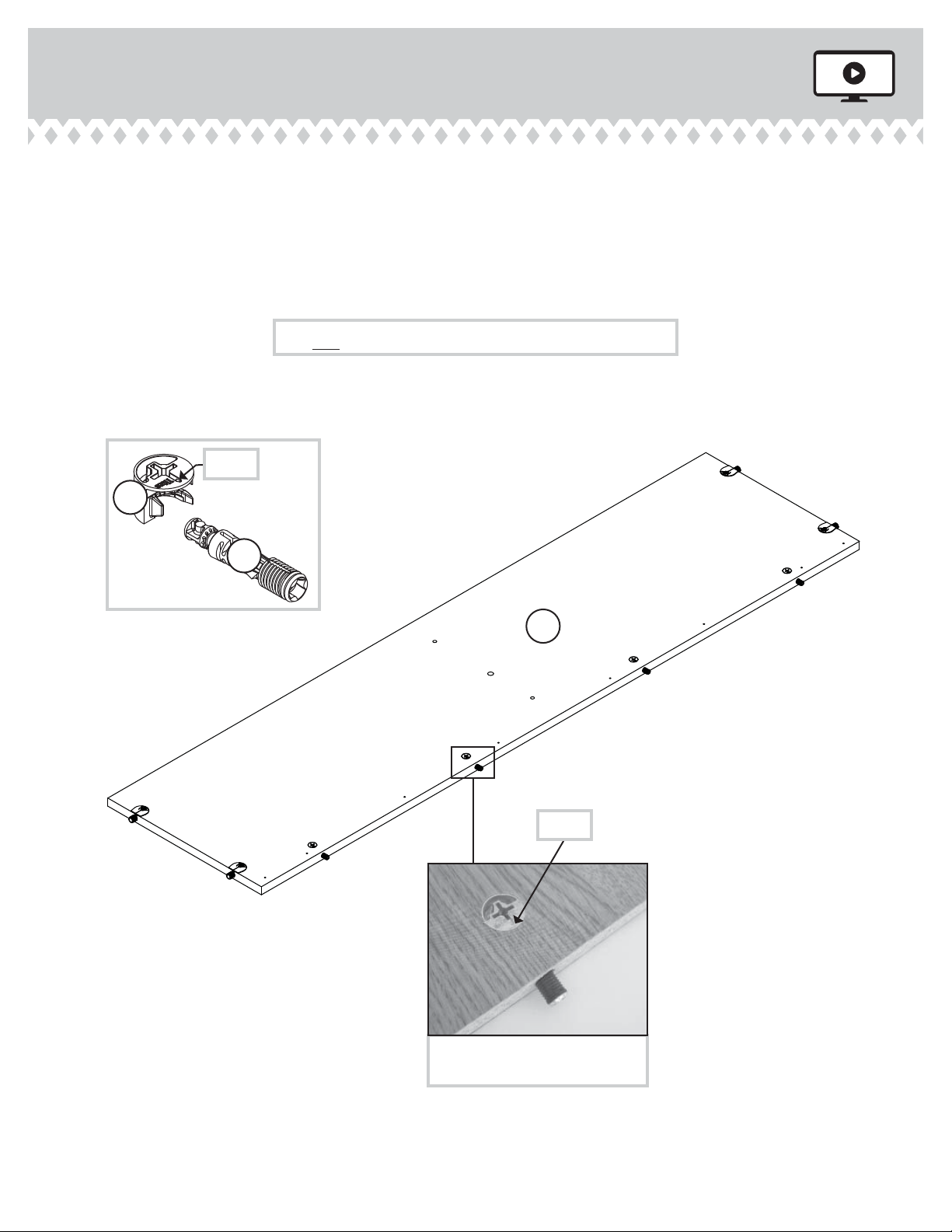
TWIST-LOCK®
FASTENER - 12
10F
FOOT - 1
3E
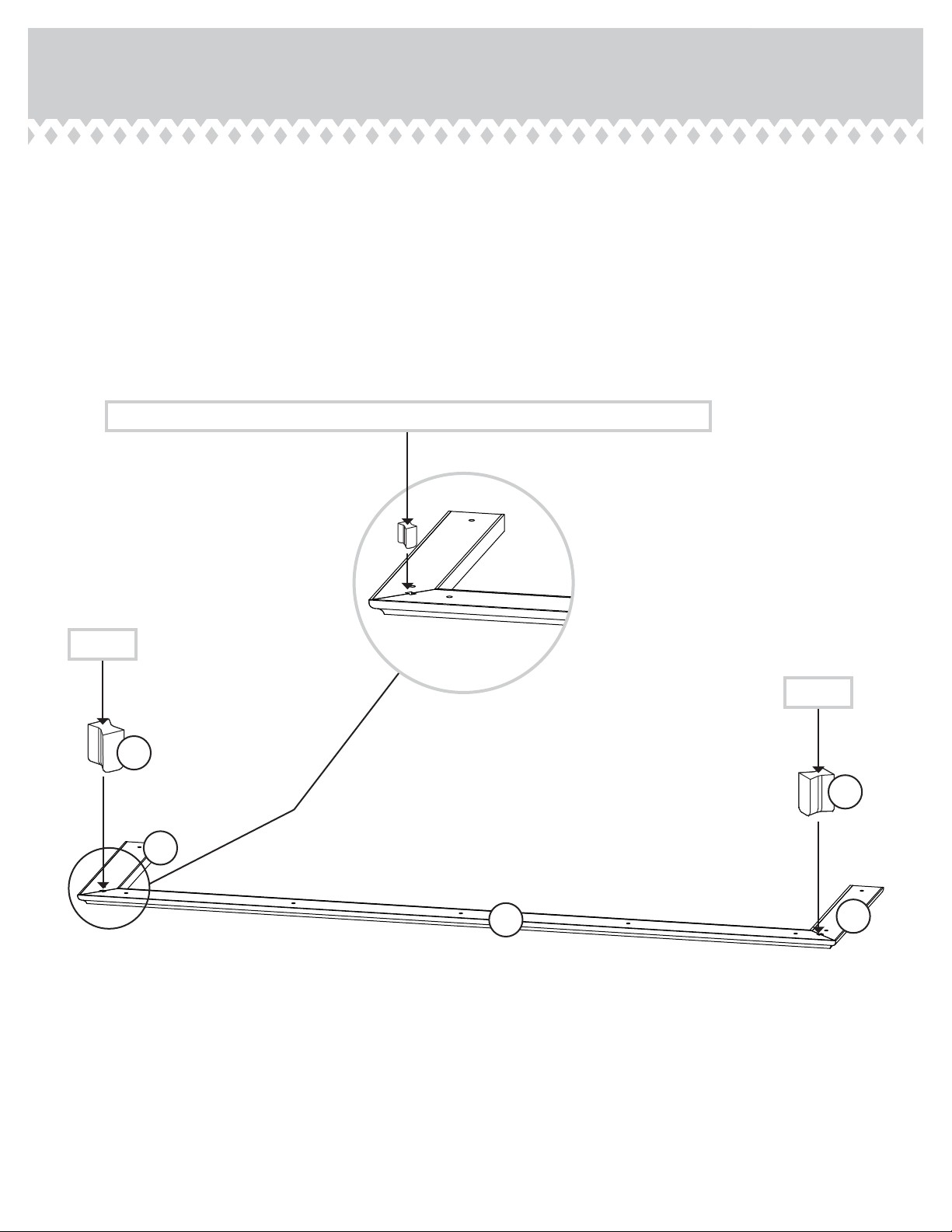
MOLDING
CONNECTOR - 2
17F TIE PLATE - 2
3G
NAIL - 60
1N
CAM SCREW - 6
8F1F HIDDEN
CAM - 10 2F CAM DOWEL- 4
420613 www.sauder.com/servicesPage 4
8G DRAWER FRONT
BRACKET - 2
LARGE DRAWER
FRONT BRACKET - 4
9G
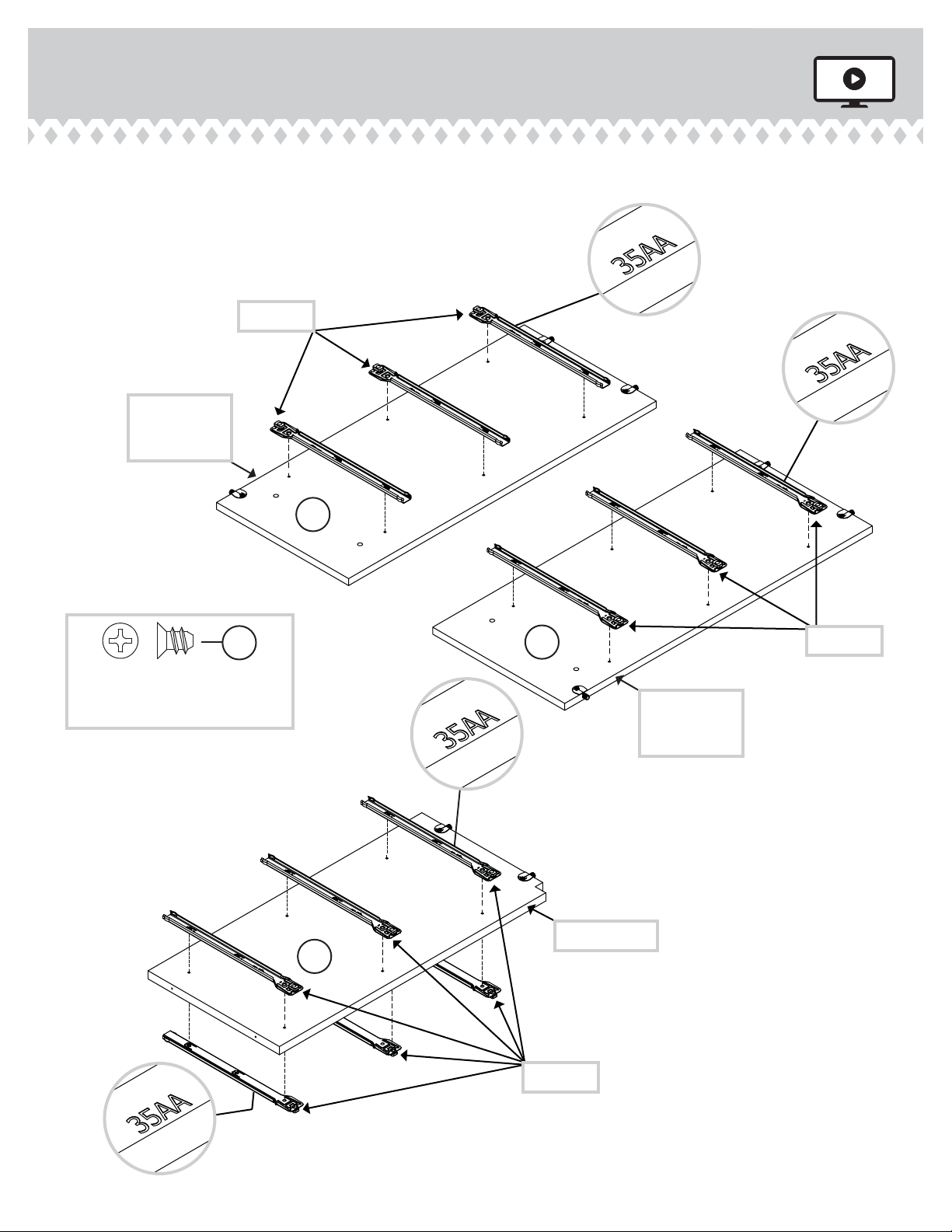
35AA 35AD35AC
UNIVERSAL CABINET RAIL - 12 DRAWER RIGHT - 6 DRAWER LEFT - 6
Locate this nylon SAFETY
STRAP (60M) to be used
later in assembly. Do not
accidentally throw away.
SAFETY STRAP - 1
60M SAFETY DRYWALL
ANCHOR - 1
61M
WASHER - 1
13M
11L WARNING LABEL - 1
(Refer to Step 17 for proper location and application)
WARNING AVERTISSEMENT ADVERTENCIA
Serious or fatal crushing injuries can
occur from furniture tipover.
To help prevent tipover:
• Install tipover restraint provided.
• Place heaviest items in the lower drawers.
• Unless specifically designed to
accommodate, do not set TVs or other
heavy objects on top of this product.
• Never allow children to climb or hang on
drawers, doors, or shelves.
• Never open more than one drawer at a time.
(OR)
• Do not defeat or remove the drawer
interlock system.
Use of tipover restraints may only reduce,
but not eliminate, the risk of tipover.
This is a permanent label. Do not remove.
Des blessures graves ou fatales par écrasement
peuvent survenir si le mobilier bascule. Pour
prévenir le basculement:
• Installer le dispositif anti-basculement fourni.
• Placer les articles plus lourds dans les tiroirs inférieurs.
• Sauf si le meuble a été conçu spécialement à
cette fin, ne pas mettre de téléviseur ou d’autre
objets lourds sur le dessus de ce meuble.
• Ne jamais laisser d’enfants grimper sur les
tiroirs, les portes ou les étagères ou s’y agripper.
• Ne jamais ouvrir plus d’un tiroir à la fois.
(OU)
• Ne pas démanteler ou enlever le système de
verrouillage pour tiroir.
L’utilisation de dispositifs anti-basculement peut
réduire le risque de basculement, mais pas l’éliminer.
Cette étiquette est permanente. Ne pas l’enlever.
Lesiones graves o fatales por aplastamiento, pueden
ocurrir por el volcar de los muebles. Para ayudar a
prevenir que se volqué:
• Instalar la contención brindada para evitar que se volqué.
• Coloque los artículos más pesados en los cajones
inferiores.
• A menos que sea específicamente diseñado para
acomodar, no establezca televisores u otros objetos
pesados en la parte superior de este producto.
• Nunca permita que los niños se suban o se cuelguen
de cajones, puertas o estantes.
• Nunca abra más de un cajón a la vez.
(O)
• No anule o elimine el sistema de bloqueo de los cajones.
El uso de la contención puede solamente reducir, pero
no eliminar, el riesgo de volcar.
Esta es una etiqueta permanente. No remover.
10/16 395783
METAL
BRACKET - 8
4G
KNOB SET - 12
130K