manuals.online logo
Brands
  1. Home
  2. •
  3. Brands
  4. •
  5. Sauder
  6. •
  7. Indoor Furnishing
  8. •
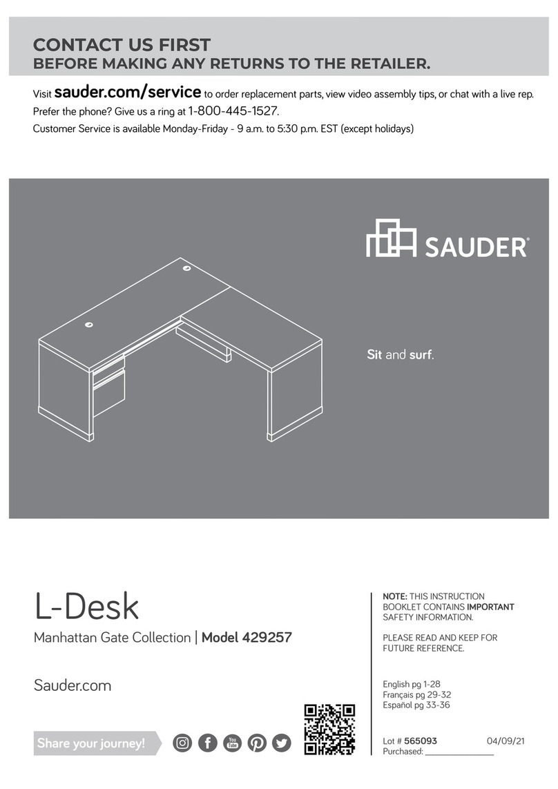
  9. Sauder Adept Storage Series User manual

Sauder Adept Storage Series User manual

Need help? Visit Sauder.com to view video assembly tips or chat with a live rep.
Prefer the phone? Call 1-800-523-3987.
Share your journey!
sauder.com
You'll love what we
have in storage.
NOTE: THIS INSTRUCTION
BOOKLET CONTAINS IMPORTANT
SAFETY INFORMATION.
PLEASE READ AND KEEP FOR
FUTURE REFERENCE.
English pg 1-18
Français pg 19-21
Español pg 22-24
Lot # 365818 10/13/14
Purchased: __________________
Be sure to give us a ring before
making any returns. 1-800-523-3987
Storage Crendenza
Adept Storage Collection | 418344
Table of Contents Assembly Tools Required
Hammer
Not actual size
No. 2 Phillips Screwdriver
Tip Shown Actual Size
WARNING
!
Skip the power trip.
This time.
3
4
5-18
19-21
22-24
25-26
27
Part Identification
Hardware Identification
Assembly Steps
Français
Español
Safety
Warranty
Use of a TV that is too heavy or large is hazardous. A TV that is too heavy will create a risk of a tip-over that can cause severe injury or
death. A TV that is too large for the available space might be accidentally pushed or bumped o the furniture, or subject to tip-over.
• Check the size and weight of your TV. Compare it to the diagram below – before you begin assembly!
• This Sauder unit is designed for use with televisions weighing less than 50 pounds. Never use with a TV that weighs more.
• The size of the television, front-to-back and side-to-side, must fit within the space defined in the diagram.
• Never place the front edge of the TV past the front edge of the TV support shelf (or stop molding – if equipped)
• Never allow the sides of the TV to extend past the side edges of the TV support surface.
• If the TV has a CRT picture tube, the picture tube cone may extend past the rear of the support shelf.
• Be sure to apply the warning label as instructed in the last assembly step. The label provides important safety related information.
50 lbs.
50 lbs.
17-1/8"
17-1/8"
58-1/4"
58-1/4"
418344 www.sauder.com/servicesPage 2
Part Identification
åWhile not all parts are labeled, some of the parts will have a label or an inked letter on the edge
to help distinguish similar parts from each other. Use this part identification to help identify similar parts.
Now you know
our ABCs.
A END (2)
B UPRIGHT (2)
C SMALL UPRIGHT (2)
D TOP (1)
E BOTTOM (1)
F SHELF (1)
G BACK (1)
H ADJUSTABLE SHELF (3)
I LEFT FRONT/RIGHT REAR LEG (2)
J RIGHT FRONT/LEFT REAR LEG (2)
K BOTTOM MOLDING (1)
L SHELF MOLDING (1)
M END MOLDING (2)
A
AB
B
C
C
D
E
F
G
H
H
H
I
I
J
J
K
L
M
M
418344www.sauder.com/services Page 3
Hardware Identification
åScrews are shown actual size. You may receive extra hardware with your unit.
SILVER 1/2" MACHINE SCREW - 6
38S
METAL BRACKET - 4
4G
BLACK 9/16" LARGE HEAD SCREW - 16
1S BLACK 1-7/8" FLAT HEAD SCREW - 8
2S
CAM COVER - 24
13P METAL PIN - 12
1R
HOLE PLUG - 2
41P
BLACK 9/16" FLAT HEAD SCREW - 4
32S
CAM SCREW - 16
8F
WOOD DOWEL - 4
15F
NAIL - 64
1N
HIDDEN CAM - 36
1F CAM DOWEL - 20
2F
CARD HOLDER - 3
35M
RUBBER SLEEVE - 12
2R
DECORATIVE NAIL - 4
3N
ADJUSTABLE FOOT - 2
34E
WARNING
Never use this furniture with a TV that is
too large or too heavy. Severe injury or
death can occur.The TV and furniture
will be unstable and may tip.
-The TV must less than 50 lbs.
-The base of the TV must be able to sit
completely on this shelf.
Refer to instruction book for complete
safety information.
Note: This is a permanent label. Do not
try to remove. Surface will be damaged.
08/05 2 6 9 2 2 0 269220
WARNING LABEL - 1
1L
(Refer to the last step for proper
location and application)
CARD SHEET - 1
38M
418344 www.sauder.com/servicesPage 4
Step 1 Look for this icon. It means a
video assembly tip is available at
www.sauder.com/services/tips
å Assemble your unit on a carpeted floor or on the empty
carton to avoid scratching your unit or the floor.
å Push thirty-six HIDDEN CAMS (1F) into the ENDS (A),
UPRIGHTS (B), SMALL UPRIGHTS (C), BOTTOM (E),
and SHELF (F). Then, insert the metal end of a
CAM DOWEL (2F) into each HIDDEN CAM except in
the long edges of the ENDS (A) and SHELF (F).
Arrow
1F
2F
(36 used)
(20 used)
Arrow
1F
2F
Do not tighten the HIDDEN CAMS in this step.
Do not insert CAM DOWELS into these edges.
Insert the metal end of the CAM
DOWEL into the HIDDEN CAM.
Arrow
C
C
E
F
A
A
B
B
418344www.sauder.com/services Page 5
å Turn sixteen CAM SCREWS (8F) into the LEGS (I and J).
and SHELF MOLDING (L).
Step 2
8F
J
J
I
I
L
418344 www.sauder.com/servicesPage 6
(16 used)
Step 3
J
I
å Insert two WOOD DOWELS (15F) into the holes in the
ENDS (A).
å Fasten the LEGS (I and J) to the ENDS (A). Tighten six
HIDDEN CAMS.
å NOTE: Be sure the WOOD DOWELS insert into the
LEGS (I and J).
12
A
A
These edges must be even.
15F
15F
418344www.sauder.com/services Page 7
Some assembly
(and snacks) required.
Step 4
å Flip the ENDS (A) over.
å Turn four BLACK 9/16" FLAT HEAD SCREWS (32S) into
the ENDS (A) until the shoulder of the SCREWS rest on
the surface of the ENDS.
å Slide the END MOLDINGS (M) onto the ENDS (A). Line
up the groove in the MOLDINGS over the head of the
SCREWS in the ENDS.
These edges
should be even.
These edges
should be even.
Shoulder
Apply pressure with your hands
as you guide the MOLDINGS over
the SCREWS and onto the ENDS.
BLACK 9/16" FLAT HEAD SCREW
(4 used in this step)
32S
A
A
M
MM
418344 www.sauder.com/servicesPage 8
å Flip the ENDS (A) over.
å Insert two WOOD DOWELS (15F) into the holes in
the ENDS (A).
å Fasten the remaining LEGS (I and J) to the ENDS (A).
Tighten six HIDDEN CAMS.
å NOTE: Be sure the WOOD DOWELS insert into the
LEGS (I and J).
Step 5
A
A
These edges must be even.
J
I
12
418344www.sauder.com/services Page 9
15F
å Fasten an END (A) to the TOP (D). Tighten two
HIDDEN CAMS.
å Fasten the SMALL UPRIGHTS (C) to the TOP (D). Tighten
four HIDDEN CAMS.
Step 6
D
C
C
A
Surface with HIDDEN CAMS
Finished edge
Start Tighten
Arrow
Minimum
190 degrees
Caution
Risk of damage or
injury. HIDDEN CAMS
must be completely
tightened. HIDDEN
CAMS that are not
completely tightened
may loosen, and parts
may separate. To
completely tighten:
Arrow
Maximum
210 degrees
418344 www.sauder.com/servicesPage 10
å Fasten the SHELF (F) to the END (A). Tighten two
HIDDEN CAMS.
å Fasten the SHELF (F) to the SMALL UPRIGHTS (C). Use
four BLACK 1-7/8" FLAT HEAD SCREWS (2S).
Step 7
A
C
C
F
BLACK 1-7/8" FLAT HEAD SCREW
(4 used in this step)
2S
Arrow
Minimum
190 degrees
Maximum
210 degrees
418344www.sauder.com/services Page 11
Surface with HIDDEN CAMS
These holes must be here.
å Fasten the UPRIGHTS (B) to the SHELF (F). Tighten four
HIDDEN CAMS.
Step 8
F
B
B
Surface with HIDDEN CAMS
Surface without HIDDEN CAMS
Arrow
Minimum
190 degrees
Maximum
210 degrees
418344 www.sauder.com/servicesPage 12
Now might be a
good time to refresh
your drink.
å Fasten the BOTTOM (E) to the END (A). Tighten two
HIDDEN CAMS.
å Fasten the BOTTOM (E) to the UPRIGHTS (B). Use four
BLACK 1-7/8" FLAT HEAD SCREWS (2S).
Step 9
B
B
Arrow
Minimum
190 degrees
Maximum
210 degrees
A
E
BLACK 1-7/8" FLAT HEAD SCREW
(4 used in this step)
2S
418344www.sauder.com/services Page 13
These holes must be here.
å Fasten three CARD HOLDERS (35M) to the SHELF
MOLDING (L) Use six SILVER 1/2" MACHINE SCREWS (38S)
as shown to the right.
å Separate the CARDS on the CARD SHEET (38M) and
insert them into the CARD HOLDERS (35M).
å Fasten the SHELF MOLDING (L) to the SHELF (F). Tighten
four HIDDEN CAMS.
å Fasten the remaining END (A) to the TOP (D), BOTTOM (E),
and SHELF (F). Tighten six HIDDEN CAMS.
Step 10
These edges are almost even.
1
2
Arrow
Minimum
190 degrees
Maximum
210 degrees
Surface
without holes
418344 www.sauder.com/servicesPage 14
A
D
E
F
L
SILVER 1/2" MACHINE SCREW
(6 used for the CARD HOLDERS)
38S L
These holes must be
closer to the top edge.
35M
38M
The open slots on the card
holders must be facing up.
å Tap four DECORATIVE NAILS (3N) into the
BOTTOM MOLDING (K) as shown to the right.
å Fasten four METAL BRACKETS (4G) to the
BOTTOM (E). Use four BLACK 9/16" LARGE
HEAD SCREWS (1S).
å NOTE: Be sure the BRACKETS are even with the
edge of the BOTTOM.
å Fasten the BOTTOM MOLDING (K) to the
BRACKETS on the BOTTOM (E). Use four BLACK
9/16" LARGE HEAD SCREWS (1S).
Step 11
These edges must be even.
BLACK 9/16" LARGE HEAD SCREW
(8 used in this step)
1S
4G
K
K
E
418344www.sauder.com/services Page 15
3N
Finished surface
å Carefully turn your unit over onto its front edges. Unfold the BACK (G) and lay it over your unit.
å Make equal margins along the two long edges and along the two short edges of the BACK (G). Push on opposite corners
of your unit if needed to make it "square".
å Fasten the BACK (G) to your unit using the NAILS (1N).
å NOTE: Be sure to tap NAILS into the holes that line up over the SHELF and UPRIGHTS.
å Fasten the ADJUSTABLE FOOT (34E) to the BOTTOM (E). Use eight BLACK 9/16" LARGE HEAD SCREWS (1S).
å NOTE: Adjustments to the ADJUSTABLE FEET will be made in Step 13 once your unit is standing upright.
Step 12
34E
Do not stand the unit upright without the
BACK fastened. The unit may collapse.
Caution
Unfinished surface
These holes must line up over
the SHELF and UPRIGHTS.
NAIL
(64 used in this step)
1N
BLACK 9/16" LARGE HEAD SCREW
(8 used for the FEET)
1S
E
G
418344 www.sauder.com/servicesPage 16
å Carefully stand your unit upright.
å Position your unit in its final location.
å Turn the ADJUSTABLE FEET (34E) downward until they
touch the floor.
å IMPORTANT: The ADJUSTABLE FEET should not extend
beyond the bottom edges of the LEGS (I and J).
Step 13
With your No. 2 Phillips Screwdriver,
turn the ADJUSTABLE FEET
downward until they touch the floor.
34E
Floor
I
I
J
J
418344www.sauder.com/services Page 17
Almost time to
celebrate! With a nap.
Step 14
WARNING
Never use this furniture with a TV
that is too large or too heavy. Severe
injury or death can occur. The TV and
furniture will be unstable and may tip.
-The TV must weigh less than 50 lbs.
-The base of the TV must be able to
sit completely on this shelf.
Refer to instruction book for
complete safety information.
Note: This is a permanent label. Do
not try to remove. Surface will be
damaged.
1L
50 lbs.
25 lbs.
25 lbs.
25 lbs.
50 lbs.
total
30 lbs. total
å Apply the WARNING LABEL (1L) to the TOP (D). You should be able to read the label when the TV is removed from the
unit. When the TV is in place, it should hide the label. Peel o the backing and apply the label as shown in the diagram.
å NOTE: This is a permanent label intended to last for the life of the product. Once applied, do not try to remove it.
å Push the RUBBER SLEEVES (2R) over the METAL PINS (1R). Insert the METAL PINS into the hole locations of your choice
in the ENDS (A) and UPRIGHTS (B). Set the ADJUSTABLE SHELVES (H) onto the METAL PINS.
å Push two HOLE PLUGS (41P) into the holes in the BOTTOM (E).
å Push a CAM COVER (13P) onto each HIDDEN CAM.
å NOTE: Please read the back pages of the instruction booklet for important
safety information.
å This completes assembly. To clean your unit, dampen a cloth with tap water and wipe.
(12 used)
(24 used)
2R
1R
41P
E
And to celebrate, why not share your success story?
A
A
B
B
H
H
H
D
418344 www.sauder.com/servicesPage 18
To cover HIDDEN CAMS
13P
A l’usage exclusif du
Canada Noter la date
d’achat de cet élément
et conserver le livret
pour future référence.
Pour contacter Sauder
en ce qui concerne cet
élément, faire référence
au numéro de lot et
numéro de modèle en
appelant notre numéro
sans frais.
Lot nº : ____________
Date de
l’achat: ____________
LISTE DE PIÈCES
REFERENCE DESCRIPTION QUANTITÉ
LISTE DE PIÈCES
REFERENCE DESCRIPTION QUANTITÉ
NOUS SOMMES LA POUR VOUS AIDER!
Nous faisons de notre mieux pour nous assurer que votre meuble
arrive dans d’excellentes conditions. Nos représentants du service
Clientèle sont aimables et prêts à vous aider au cas où une pièce
aurait été endommagée ou manquerait (ou si vous aviez besoin
d’aide pour l’assemblage). NE RAMENEZ PAS LE MEUBLE AU
MAGASIN. Au Canada, composez ce numéro d’appel gratuit:
1-800-523-3987
Du lundi au vendredi, de 9 heures du matin à
5:30 heures du soir (horaire Côte Est)
(sauf jours fériés)
Si une pièce a besoin d’être remplacée, la pièce de remplacement
sera envoyée dans les 48 heures. (Sauf week-ends et jours fériés)
Utilisez les instructions d’assemblage en français avec les
schémas étape par étape du manuel d’instruction en anglais.
Chaque étape en français correspond à la même étape
en anglais. La pièce devant être attachée à l’élément est
représentée en gris sur les schémas de chaque étape pour plus
de précision. Comparer la “Liste de pièces” ci-dessous avec
la “PART IDENTIFICATION” du manuel en anglais pour vous
familiariser avec les pièces avant l’assemblage.
REMARQUE : CE MANUEL D’INSTRUCTIONS CONTIENT
D’IMPORTANTES INFORMATIONS RELATIVES À LA SÉCURITÉ.
À LIRE ET CONSERVER POUR TOUTE RÉFÉRENCE FUTURE.
(Consulter la dernière étape pour l'emplacement
et application appropriées)
35M PORTE-CARTES..........................................................3
38M FEUILLE DE CARTES................................................1
1N CLOU ................................................................................64
3N CLOU DÉCORATIF.....................................................4
41P BOUCHON.......................................................................2
13P COUVERCLE D'EXCENTRIQUE....................24
1R GOUPILLE EN MÉTAL...........................................12
2R MANCHON EN CAOUTCHOUC...................12
1S VIS TÊTE LARGE 14 mm NOIRE..................16
2S VIS TÊTE PLATE 48 mm NOIRE.....................8
32S VIS TÊTE PLATE 14 mm NOIRE......................4
38S VIS À MÉTAUX 13 mm ARGENTÉE..............6
A EXTRÉMITÉ......................................................................2
B MONTANT.........................................................................2
C PETIT MONTANT........................................................2
D DESSUS...............................................................................1
E DESSOUS...........................................................................1
F TABLETTE..........................................................................1
G ARRIÈRE ..............................................................................1
H TABLETTE RÉGLABLE............................................3
I PIED AVANT GAUCHE/ARRIÈRE DROIT..2
J PIED AVANT DROIT/ARRIÈRE GAUCHE..2
K MOULURE DE DESSOUS......................................1
L MOULURE DE TABLETTE .....................................1
M MOULURE D’EXTRÉMITÉ.....................................2
34E PIED RÉGLABLE...........................................................2
1F EXCENTRIQUE ESCAMOTABLE.................36
2F CHEVILLE D'EXCENTRIQUE ..........................20
8F VIS D'EXCENTRIQUE ............................................ 16
15F CHEVILLE EN BOIS...................................................4
4G CONSOLE EN MÉTAL .............................................4
1L ÉTIQUETTE DE MISE EN GARDE....................1
Crédence de rangement418344
418344www.sauder.com/services Page 19
ÉTAPE 4
Retourner les EXTRÉMITÉS (A).
Faire tourner quatre VIS TÊTE PLATE 14 mm NOIRES (32S) dans
les EXTRÉMITÉS (A) jusqu'à ce que l'épaulement des VIS repose
sur la surface des EXTRÉMITÉS.
Enfiler les MOULURES D'EXTRÉMITÉ (M) sur les EXTRÉMITÉS (A).
Aligner la rainure des MOULURES sur les têtes des VIS dans
les EXTRÉMITÉS.
ÉTAPE 5
Retourner les EXTRÉMITÉS (A).
Insérer deux CHEVILLES EN BOIS (15F) dans les trous des
EXTRÉMITÉS (A).
Fixer les autres PIEDS (I et J) aux EXTRÉMITÉS (A). Serrer six
EXCENTRIQUES ESCAMOTABLES.
REMARQUE : S’assurer d’insérer les CHEVILLES EN BOIS dans
les PIEDS (I et J).
ÉTAPE 6
Fixer une EXTRÉMITÉ (A) au DESSUS (D). Serrer deux
EXCENTRIQUES ESCAMOTABLES.
Fixer les PETITS MONTANTS (C) au DESSUS (D). Serrer quatre
EXCENTRIQUES ESCAMOTABLES.
Attention: Risque des dégâts ou blessures. Les Excentriques
Escamotables doivent être serrés à bloc. Les Excentriques
Escamotables que ne sont pas serrées à bloc peuvent desserrer
et les pièces peuvent séparer. Pour serrer à bloc, faire tourner
l'excentrique escamotable de 210 degrés.
ÉTAPE 7
Fixer la TABLETTE (F) à l'EXTRÉMITÉ (A). Serrer deux
EXCENTRIQUES ESCAMOTABLES.
Fixer la TABLETTE (F) aux PETITS MONTANTS (C). Utiliser quatre
VIS TÊTE PLATE 48 mm NOIRES (2S).
ÉTAPE 8
Fixer les MONTANTS (B) à la TABLETTE (F). Serrer quatre
EXCENTRIQUES ESCAMOTABLES.
ÉTAPE 3
Insérer deux CHEVILLES EN BOIS (15F) dans les trous des
EXTRÉMITÉS (A).
Fixer les PIEDS (I et J) aux EXTRÉMITÉS (A). Serrer six
EXCENTRIQUES ESCAMOTABLES.
REMARQUE : S’assurer d’insérer les CHEVILLES EN BOIS
dans les PIEDS (I et J).
ÉTAPE 1
Ne pas serrer les EXCENTRIQUES ESCAMOTABLES dans cette étape.
Assembler l'élément sur un sol à moquette ou sur le carton vide
pour éviter d'endommager l'élément ou le sol.
Enfoncer trente-six EXCENTRIQUES ESCAMOTABLES (1F) dans les
EXTRÉMITÉS (A), les MONTANTS (B), les PETITS MONTANTS (C), le
DESSOUS (E) et la TABLETTE (F). Insérer ensuite l'extrémité en métal
d'une CHEVILLE D’EXCENTRIQUE (2F) dans chaque EXCENTRIQUE
ESCAMOTABLE, à l'exception des chants longs des EXTRÉMITÉS (A)
et de la TABLETTE (F).
ÉTAPE 2
Faire tourner seize VIS D'EXCENTRIQUE (8F) dans les PIEDS (I et J)
et la MOULURE DE TABLETTE (L).
AVERTISSEMENT
L'utilisation d'un téléviseur trop lourd ou trop gros est dangereuse.
Un téléviseur trop lourd créera un risque de basculement pouvant
provoquer de graves blessures ou la mort. Un téléviseur trop gros
pour l'espace disponible risque d'être accidentellement poussé ou
de tomber du mobilier ou d'être sujet à basculer.
• Vérifier la taille et le poids du téléviseur. Le comparer au
diagramme ci-dessous avant de commencer l'assemblage !
• Cette unité Sauder est conçue pour les téléviseurs pesant moins
de 22 kg. Ne jamais utiliser avec des téléviseurs plus lourds.
• La taille du téléviseur, d'avant en arrière et latéralement, doit
rentrer dans l'espace défini sur le schéma.
• Ne jamais placer le devant du téléviseur au-delà du devant de
la tablette de support de téléviseur (ou de la moulure de butée, le
cas échéant).
• Ne jamais laisser les côtés du téléviseur dépasser les bords
latéraux de la surface de support du téléviseur.
• Si le téléviseur comporte un tube cathodique à image, le cône du
tube image peut dépasser l'arrière de la tablette de support.
• S'assurer d'apposer l'étiquette d'avertissement comme indiqué
à la dernière étape d'assemblage. L'étiquette fournit d'importants
renseignements relatifs à la sécurité.
418344 www.sauder.com/servicesPage 20

This manual suits for next models

1

Other Sauder Indoor Furnishing manuals
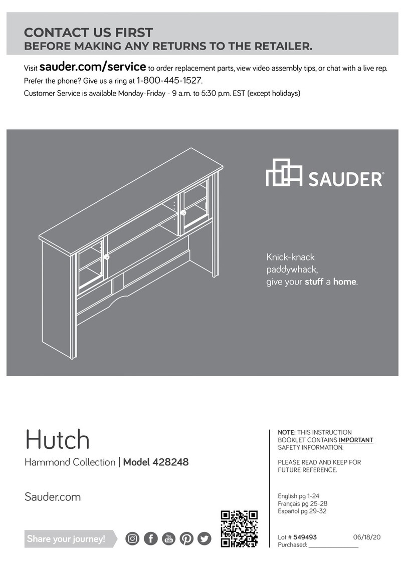
Sauder 419517 User manual

Sauder

Sauder 419517 User manual

Sauder Shoal Creek 408920 User manual

Sauder

Sauder Shoal Creek 408920 User manual

Sauder Anda Norr 427707 User manual

Sauder

Sauder Anda Norr 427707 User manual

Sauder Nova Loft 425510 User manual

Sauder

Sauder Nova Loft 425510 User manual

Sauder Carson Forge 412920 User manual

Sauder

Sauder Carson Forge 412920 User manual

Sauder Summer Home Pantry 401867 User manual

Sauder

Sauder Summer Home Pantry 401867 User manual

Sauder Adept 418085 User manual

Sauder

Sauder Adept 418085 User manual

Sauder 426928 User manual

Sauder

Sauder 426928 User manual

Sauder Dakota Pass 419119 User manual

Sauder

Sauder Dakota Pass 419119 User manual

Sauder Harbor View 403793 User manual

Sauder

Sauder Harbor View 403793 User manual

Sauder 420449 User manual

Sauder

Sauder 420449 User manual

Sauder WHISKER User manual

Sauder

Sauder WHISKER User manual

Sauder 412885 User manual

Sauder

Sauder 412885 User manual

Sauder Entertainment Credenza 427465 User manual

Sauder

Sauder Entertainment Credenza 427465 User manual

Sauder OfficeWorks AFFIRM 427440 User manual

Sauder

Sauder OfficeWorks AFFIRM 427440 User manual

Sauder Cannery Bridge 429414 User manual

Sauder

Sauder Cannery Bridge 429414 User manual

Sauder Via 419642 User manual

Sauder

Sauder Via 419642 User manual

Sauder Office Port 408294 User manual

Sauder

Sauder Office Port 408294 User manual

Sauder 422807 User manual

Sauder

Sauder 422807 User manual
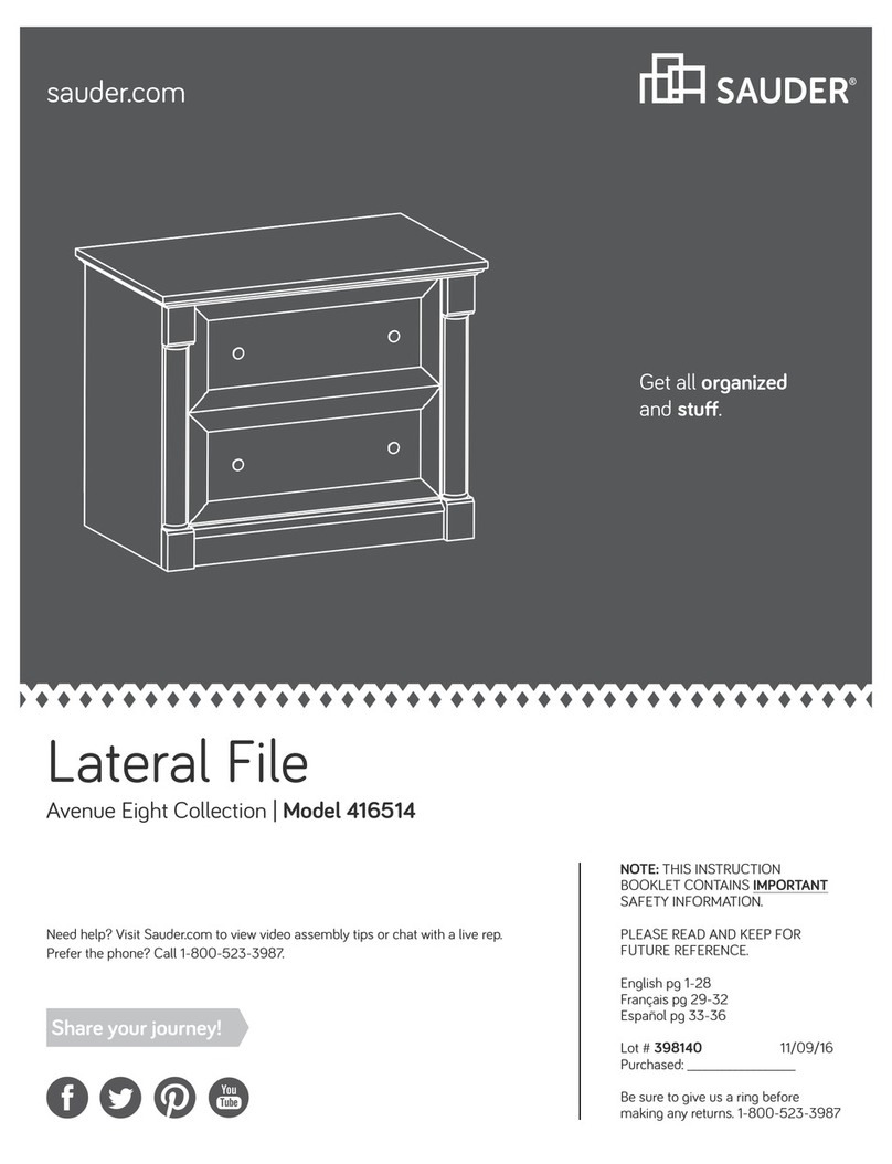
Sauder Graham Hill 422811 User manual

Sauder

Sauder Graham Hill 422811 User manual

Sauder Executive Desk 408289 User manual

Sauder

Sauder Executive Desk 408289 User manual

Sauder 433242 User manual

Sauder

Sauder 433242 User manual

Sauder 413123 User manual

Sauder

Sauder 413123 User manual

Sauder 409942 User manual

Sauder

Sauder 409942 User manual

Popular Indoor Furnishing manuals by other brands

Bell'O WAVS335 Assembly instructions

Bell'O

Bell'O WAVS335 Assembly instructions

Children's Products Simmons Kids SlumberTime 310210-499 Assembly instructions

Children's Products

Children's Products Simmons Kids SlumberTime 310210-499 Assembly instructions

Wilding Wallbeds Brittany Installation booklet

Wilding Wallbeds

Wilding Wallbeds Brittany Installation booklet

Crate&Barrel Warren manual

Crate&Barrel

Crate&Barrel Warren manual

GEM SHORT BED WITH SIDES KIT quick start guide

GEM

GEM SHORT BED WITH SIDES KIT quick start guide

Lehner Versand Lea 58729 Assembly instruction

Lehner Versand

Lehner Versand Lea 58729 Assembly instruction

OAKWORKS Spa Clinician Adjustable Lift-Assist Salon Top user manual

OAKWORKS Spa

OAKWORKS Spa Clinician Adjustable Lift-Assist Salon Top user manual

HENN 102-10 Assembly instructions

HENN

HENN 102-10 Assembly instructions

DAYCO DM0906 quick start guide

DAYCO

DAYCO DM0906 quick start guide

Forte SEWK522 Assembling Instruction

Forte

Forte SEWK522 Assembling Instruction

Jorgenson Lockers Gladiator Assembling instructions

Jorgenson Lockers

Jorgenson Lockers Gladiator Assembling instructions

Global Contract Compile installation manual

Global Contract

Global Contract Compile installation manual

Niche Flip Flop FF2822 Series Assembly instructions

Niche

Niche Flip Flop FF2822 Series Assembly instructions

Extremis Marina bistro manual

Extremis

Extremis Marina bistro manual

NORMBAU NY.466.110 Fixing instructions

NORMBAU

NORMBAU NY.466.110 Fixing instructions

BLACK RED WHITE STYLIUS NBIU 170 Assembly manual

BLACK RED WHITE

BLACK RED WHITE STYLIUS NBIU 170 Assembly manual

Kidco BR202 user guide

Kidco

Kidco BR202 user guide

LumiSource BOOMCHAIR SVC owner's manual

LumiSource

LumiSource BOOMCHAIR SVC owner's manual

manuals.online logo
manuals.online logoBrands
  • About & Mission
  • Contact us
  • Privacy Policy
  • Terms and Conditions

Copyright 2025 Manuals.Online. All Rights Reserved.