manuals.online logo
Brands
  1. Home
  2. •
  3. Brands
  4. •
  5. Sauder
  6. •
  7. Indoor Furnishing
  8. •
  9. Sauder Shoal Creek 417678 User manual

Sauder Shoal Creek 417678 User manual

Need help? Visit Sauder.com to view video assembly tips or chat with a live rep.
Prefer the phone? Call 1-800-523-3987.
Share your journey!
sauder.com
NOTE: THIS INSTRUCTION
BOOKLET CONTAINS IMPORTANT
SAFETY INFORMATION.
PLEASE READ AND KEEP FOR
FUTURE REFERENCE.
English pg 1-31
Français pg 32-35
Español pg 36-39
Lot # 363510 08/26/14
Purchased: __________________
Be sure to give us a ring before
making any returns. 1-800-523-3987
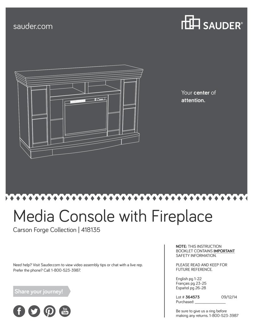
Entertainment Credenza
Shoal Creek Collection | 417678
Entertaining what
entertains you.
Table of Contents Assembly Tools Required
Part Identification
Hardware Identification
Assembly Steps
Français
Español
Safety
Warranty
Hammer
Not actual size
No. 2 Phillips Screwdriver
Tip Shown Actual Size
Skip the power trip.
This time.
3
4
5-31
32-35
36-39
40-42
43
95 lbs.
95 lbs.
19-1/2"
19-1/2"
58"
58"
WARNING
!
Use of a TV that is too heavy or large is hazardous. A TV that is too heavy will create a risk of a tip-over that can cause severe injury or
death. A TV that is too large for the available space might be accidentally pushed or bumped o the furniture, or subject to tip-over.
• Check the size and weight of your TV. Compare it to the diagram below – before you begin assembly!
• This Sauder unit is designed for use with televisions weighing less than 95 pounds. Never use with a TV that weighs more.
• The size of the television, front-to-back and side-to-side, must fit within the space defined in the diagram.
• Never place the front edge of the TV past the front edge of the TV support shelf (or stop molding – if equipped)
• Never allow the sides of the TV to extend past the side edges of the TV support surface.
• If the TV has a CRT picture tube, the picture tube cone may extend past the rear of the support shelf.
• Be sure to apply the warning label as instructed in the last assembly step. The label provides important safety related information.
417678 www.sauder.com/servicesPage 2
Part Identification
åWhile not all parts are labeled, some of the parts will have a label or an inked letter on the edge
to help distinguish similar parts from each other. Use this part identification to help identify similar parts.
Now you know
our ABCs.
A RIGHT END (1)
B LEFT END (1)
C ROLL-OUT RIGHT END (1)
D ROLL-OUT LEFT END (1)
E RIGHT UPRIGHT (1)
F LEFT UPRIGHT (1)
G TOP (1)
H BOTTOM (1)
I ROLL-OUT BOTTOM (1)
J BACK (2)
K ROLL-OUT BACK (1)
L ADJUSTABLE SHELF (4)
M LARGE ADJUSTABLE SHELF (1)
N RIGHT DOOR (1)
O LEFT DOOR (1)
P RIGHT LEG (3)
Q LEFT LEG (3)
R BASE (1)
S SIDE BASE (2)
T FLIP-UP DRAWER FRONT (1)
U LARGE BACK (1)
V SMALL DOOR (2)
W BOTTOM MOLDING (1)
X SIDE BOTTOM MOLDING (2)
Y END MOLDING (2)
417678www.sauder.com/services Page 3
UA
B
C
D
E
F
G
H
I
J
K
L
M
N
O
P
Q
R
S
T
J
L
L
L
V
W
X
Y
S
Y
V
X
P
PQ
Q
Hardware Identification
åScrews are shown actual size. You may receive extra hardware with your unit.
417678 www.sauder.com/servicesPage 4
3M ANTI-SKID
PAD - 1
(Refer to step 27 for proper
location and application)
WARNING LABEL - 1
3L
WARNING
Never use this furniture with a TV that is too
large or too heavy. Severe injury or death
can occur.The TV and furniture will be
unstable and may tip.
-The TV must less than 95 lbs.
-The base of the TV must be able to sit
completely on this shelf.
-Refer to instruction book for complete
safety information.
Note: This is a permanent label. Do not try
to remove. Surface will be damaged.
02/ 02 269227
(EXTENSION SET SHOWN SEPARATED)
EXTENSION RAIL - 2
ZEXTENSION SLIDE - 2
AA
BLACK 1-1/8" MACHINE SCREW - 6
21S
SILVER 3/4" MACHINE SCREW - 12
20S
BLACK 9/16" LARGE HEAD SCREW - 12
1S
BLACK 7/8" LARGE HEAD SCREW - 6
17S
BLACK 1-7/8" FLAT HEAD SCREW - 18
2S
3S GOLD 5/16" FLAT HEAD SCREW - 8
METAL PIN - 20
1R
SILVER 5/8" FLAT HEAD SCREW - 16
23S
PULL - 6
7K
22H
HINGE SPACER - 8
BLACK 9/16" FLAT HEAD SCREW - 4
32S
CAM SCREW - 18
8F
KNOB - 6
24K
14H HINGE - 8 DOOR STOP - 4
4I
NAIL - 48
1N
HIDDEN CAM - 32
1F CAM DOWEL - 14
2F
RUBBER SLEEVE - 20
2R
METAL BRACKET - 4
4G DRAWER BRACKET SET - 1
55G
Step 1 Look for this icon. It means a
video assembly tip is available at
www.sauder.com/services/tips
å Assemble your unit on a carpeted floor or on the empty
carton to avoid scratching your unit or the floor.
å Push thirty-two HIDDEN CAMS (1F) into the ENDS (A and B),
UPRIGHTS (E and F), BOTTOM (H), and LARGE BACK (U).
Then, insert the metal end of a CAM DOWEL (2F) into each
HIDDEN CAM except for the long ends of the ENDS (A and B)
and UPRIGHTS (E and F).
417678www.sauder.com/services Page 5
Insert the metal end of the CAM
DOWEL into the HIDDEN CAM.
Arrow
Do not tighten the HIDDEN CAMS in this step.
Arrow
The arrow in the HIDDEN
CAM must point toward the
hole in the edge of the board.
Hole
Do not insert CAM
DOWELS into these edges.
(32 used)
(14 used)
Arrow
1F
2F
Arrow
1F
Arrow
1F
Do not insert CAM
DOWELS into this edge.
A
B
E
F
H
U
Step 2
417678 www.sauder.com/servicesPage 6
8F
å Turn eighteen CAM SCREWS (8F) into the LEGS (P and Q).
P
Q
P
P
Q
Q
Step 3
417678www.sauder.com/services Page 7
å Turn four BLACK 9/16" FLAT HEAD SCREWS (32S) into
the ENDS (A and B) until the shoulder of the SCREWS
rest on the surface of the ENDS.
å Slide the END MOLDINGS (Y) onto the ENDS (A and B).
Line up the groove in the MOLDINGS over the head of the
SCREWS in the ENDS.
These edges
should be even.
These edges
should be even.
Shoulder
Apply pressure with your hands
as you guide the MOLDINGS over
the SCREWS and onto the ENDS.
BLACK 9/16" FLAT HEAD SCREW
(4 used in this step)
32S
Remember:
Righty tighty.
Lefty loosey.
A
B
Y
Y
Surface without
HIDDEN CAMS
Surface without
HIDDEN CAMS
Step 4
417678 www.sauder.com/servicesPage 8
A
B
Surface with
HIDDEN CAMS
Surface with
HIDDEN CAMS
Q
P
P
Q
å Carefully turn your ENDS over.
å Fasten the LEGS (P and Q) to the ENDS (A and B).
Tighten twelve HIDDEN CAMS. 1
2
These surfaces
should be even.
These surfaces
should be even.
Angled edge
Angled edge
Angled edge
Step 5
417678www.sauder.com/services Page 9
å Separate the EXTENSION SLIDES (AA) from the EXTENSION RAILS (Z) as shown in the upper diagram below. Be
prepared, the parts are greasy.
å Fasten two EXTENSION RAILS (Z) to the UPRIGHTS (E and F). Use four GOLD 5/16” FLAT HEAD SCREWS (3S).
å NOTE: For each EXTENSION RAIL, turn a SCREW into the hole shown in the enlarged diagram. Then, slide the
innercartridge of the EXTENSION RAIL in to find the other hole that lines up with the hole in the END. Turn a SCREW into
this hole.
å Fasten the LEGS (P and Q) to the UPRIGHTS (E and F). Tighten six HIDDEN CAMS.
Open end
Push the black lever in and pull the SLIDE from the RAIL.
GOLD 5/16" FLAT HEAD SCREW
(4 used in this step)
3S
E
F
Surface with
HIDDEN CAMS
Surface with
HIDDEN CAMS
Q
P
Angled edge
AA Z
Z
Z
Open end
Angled edge
These surfaces
should be even.
These surfaces
should be even.
Step 6
417678 www.sauder.com/servicesPage 10
å Slide the BOTTOM MOLDING (W) onto the notched edge
of the BOTTOM (H) until it is centered on the middle
notch of the BOTTOM.
å *U.S. Patent No. 5,499,886
Slide the BOTTOM MOLDING (W)
onto the notched edge.
H
W
Surface with
HIDDEN CAMS
Middle notch
Notched edge
Step 7
417678www.sauder.com/services Page 11
å Slide the SIDE BOTTOM MOLDINGS (X) onto the
notched edge of the BOTTOM (H) until they are even with
the short edges of the BOTTOM.
å *U.S. Patent No. 5,499,886
H
Surface with
HIDDEN CAMS
X
X
Slide the SIDE BOTTOM
MOLDINGS (X) onto the
notched edge.
These edges
must be even.
å Fasten the LEFT END (B) to the TOP (G). Tighten two
HIDDEN CAMS.
Step 8
417678 www.sauder.com/servicesPage 12
Start Tighten
Arrow
Minimum
190 degrees
Caution
Risk of damage or
injury. HIDDEN CAMS
must be completely
tightened. HIDDEN
CAMS that are not
completely tightened
may loosen, and parts
may separate. To
completely tighten:
Arrow
Maximum
210 degrees
Do not stand the unit upright without the
BACK fastened. The unit may collapse.
Caution
G
B
P
Surface with holes
Unfinished edge
Surface with
HIDDEN CAMS
Q
Step 9
417678www.sauder.com/services Page 13
Arrow
Minimum
190 degrees
Maximum
210 degrees
å Fasten the LEFT UPRIGHT (F) to the TOP (G). Tighten two
HIDDEN CAMS.
Surface with
HIDDEN CAMS
F
Q
G
å Fasten the LARGE BACK (U) to the TOP (G). Tighten two
HIDDEN CAMS.
Step 10
417678 www.sauder.com/servicesPage 14
Arrow
Minimum
190 degrees
Maximum
210 degrees
G
U
Surface with
HIDDEN CAMS
å Fasten the RIGHT UPRIGHT (E) to the TOP (G). Tighten
two HIDDEN CAMS.
Step 11
417678www.sauder.com/services Page 15
Arrow
Minimum
190 degrees
Maximum
210 degrees
G
E
Surface without
HIDDEN CAMS
P
å Fasten the BOTTOM (H) to the LEFT END (B). Tighten two
HIDDEN CAMS.
å Fasten the BOTTOM (H) to the UPRIGHTS (E and F) and
LARGE BACK (U). Use six BLACK 1-7/8" FLAT HEAD
SCREWS (2S).
Step 12
417678 www.sauder.com/servicesPage 16
Arrow
Minimum
190 degrees
Maximum
210 degrees
E
U
F
H
Surface with
HIDDEN CAMS
W
X
X
BLACK 1-7/8" FLAT HEAD SCREW
(6 used in this step)
2S
B
å Fasten the RIGHT END (A) to the TOP (G) and BOTTOM (H).
Tighten four HIDDEN CAMS.
Step 13
417678www.sauder.com/services Page 17
Don't worry. It isn't
Rome. This can be built
in a day.
Arrow
Minimum
190 degrees
Maximum
210 degrees
H
G
A
P
Q
Surface without
HIDDEN CAMS
Step 14
417678 www.sauder.com/servicesPage 18
å Fasten four METAL BRACKETS (4G) to the BASES (R
and S). Use four BLACK 9/16" LARGE HEAD SCREWS (1S).
å NOTE: Be sure the BRACKETS are even with the edges
of the BASES.
BLACK 9/16" LARGE HEAD SCREW
(4 used in this step)
1S
4G
R
S
S
Surface with
more holes
å Fasten the SIDE BASES (S) to the BASE (R). Use four
BLACK 1-7/8" FLAT HEAD SCREWS (2S).
Step 15
417678www.sauder.com/services Page 19
R
S
S
Surface with
METAL BRACKET
Surface without
METAL BRACKET
Surface with METAL BRACKETS
BLACK 1-7/8" FLAT HEAD SCREW
(4 used in this step)
2S
å Fasten the BASES (R and S) to the BOTTOM (H). Use four
BLACK 9/16" LARGE HEAD SCREWS (1S) through the
METAL BRACKETS on the BASES and into the BOTTOM.
Step 16
417678 www.sauder.com/servicesPage 20
R
S
S
H
BLACK 9/16" LARGE HEAD SCREW
(4 used in this step)
1S

Other Sauder Indoor Furnishing manuals
Sauder OFFICE WORKS AFFIRM 427430 User manual

Sauder

Sauder OFFICE WORKS AFFIRM 427430 User manual

Sauder Costa Credenza 422984 User manual

Sauder

Sauder Costa Credenza 422984 User manual

Sauder 409086 User manual

Sauder

Sauder 409086 User manual

Sauder 414435 User manual

Sauder

Sauder 414435 User manual

Sauder Hammond 430786 User manual

Sauder

Sauder Hammond 430786 User manual

Sauder Shoal Creek 411222 User manual

Sauder

Sauder Shoal Creek 411222 User manual

Sauder Barrister Lane 416798 User manual

Sauder

Sauder Barrister Lane 416798 User manual

Sauder New Grange 422180 User manual

Sauder

Sauder New Grange 422180 User manual

Sauder 408726 User manual

Sauder

Sauder 408726 User manual

Sauder OfficeWorks AFFIRM 427442 User manual

Sauder

Sauder OfficeWorks AFFIRM 427442 User manual

Sauder Edge Water Credenza 415321 User manual
Sauder

Sauder Edge Water Credenza 415321 User manual

Sauder 410627 User manual

Sauder

Sauder 410627 User manual

Sauder 419188 User manual

Sauder

Sauder 419188 User manual

Sauder worksense BERGEN CIRCLE 426290 User manual

Sauder

Sauder worksense BERGEN CIRCLE 426290 User manual

Sauder Stockbridge 409128 User manual

Sauder

Sauder Stockbridge 409128 User manual

Sauder Dakota Pass 422596 User manual

Sauder

Sauder Dakota Pass 422596 User manual

Sauder Jaclyn Smith 416404 User manual

Sauder

Sauder Jaclyn Smith 416404 User manual

Sauder August Hill 433851 User manual

Sauder

Sauder August Hill 433851 User manual

Sauder Harvey Park 420284 User manual

Sauder

Sauder Harvey Park 420284 User manual

Sauder Harbor View 403794 User manual

Sauder

Sauder Harbor View 403794 User manual

Sauder Office Port Series User manual

Sauder

Sauder Office Port Series User manual

Sauder WoodTrac closets 359540 User manual

Sauder

Sauder WoodTrac closets 359540 User manual

Sauder 101785 User manual

Sauder

Sauder 101785 User manual

Sauder Worksense BERGEN CIRCLE 426298 User manual

Sauder

Sauder Worksense BERGEN CIRCLE 426298 User manual

Popular Indoor Furnishing manuals by other brands

Cool Toddler Beds WF306849 Assembly instructions

Cool Toddler Beds

Cool Toddler Beds WF306849 Assembly instructions

Alera ALE-SE313014 quick start guide

Alera

Alera ALE-SE313014 quick start guide

Madeli Savona - 36” Specification & installation guide

Madeli

Madeli Savona - 36” Specification & installation guide

Ameriwood HOME Colebrook 5966503COM manual

Ameriwood HOME

Ameriwood HOME Colebrook 5966503COM manual

BENE LOFT Assembly instructions

BENE

BENE LOFT Assembly instructions

BME LYRA Assembly instruction

BME

BME LYRA Assembly instruction

Audio Visual Furniture VC-TABLE Assembly instructions

Audio Visual Furniture

Audio Visual Furniture VC-TABLE Assembly instructions

Mooreco Visionary Curve 74957 Series Assembly instructions

Mooreco

Mooreco Visionary Curve 74957 Series Assembly instructions

RUSTA ANTIBES 601500020101 manual

RUSTA

RUSTA ANTIBES 601500020101 manual

FMD Möbel 4023-004 Assembly instruction

FMD Möbel

FMD Möbel 4023-004 Assembly instruction

Livingchy Soft Opening Life Style Assembly instructions

Livingchy

Livingchy Soft Opening Life Style Assembly instructions

OAKWORKS Clodagh Leo instruction manual

OAKWORKS

OAKWORKS Clodagh Leo instruction manual

Forte SNHT1531 Assembling Instruction

Forte

Forte SNHT1531 Assembling Instruction

AMQ Amobi Team Wall Assembly guide

AMQ

AMQ Amobi Team Wall Assembly guide

Forte WHSV721L Assembly instructions

Forte

Forte WHSV721L Assembly instructions

FourStarGroup 11222299DT Assembly instructions

FourStarGroup

FourStarGroup 11222299DT Assembly instructions

Costway HU10393 Instruction booklet

Costway

Costway HU10393 Instruction booklet

SEI HO674200TX Assembly instruction

SEI

SEI HO674200TX Assembly instruction

manuals.online logo
manuals.online logoBrands
  • About & Mission
  • Contact us
  • Privacy Policy
  • Terms and Conditions

Copyright 2025 Manuals.Online. All Rights Reserved.