manuals.online logo
Brands
  1. Home
  2. •
  3. Brands
  4. •
  5. Sauder
  6. •
  7. Indoor Furnishing
  8. •
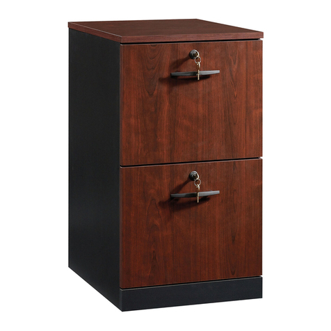
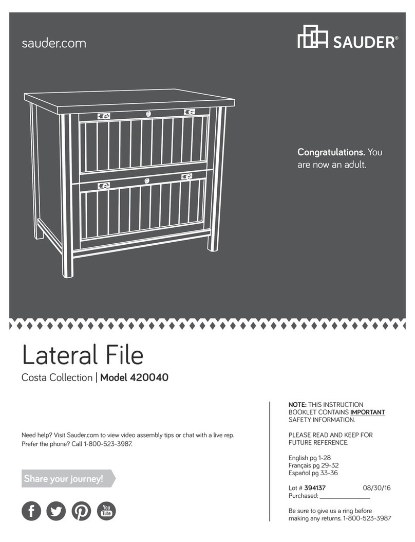
  9. Sauder Lateral File User manual

Sauder Lateral File User manual

NOTE: THIS INSTRUCTION
BOOKLET CONTAINS IMPORTANT
SAFETY INFORMATION.
PLEASE READ AND KEEP FOR
FUTURE REFERENCE.
Enlish p 1-28
Français p 29-32
Español p 33-36
05/02/19
Purchased: __________________
Share your journey!
Lateral File
When you’re feelin
nostalgic for paper.
Table of Contents Assembly Tools Required
3
4-5
6-28
29-32
33-36
37-38
39
Part Identification
Hardware Identification
Assembly Steps
Français
Español
Safety
Warranty
Hammer
Not actual size
No. 2 Phillips Screwdriver
Tip Shown Actual Size
Skip the power trip.
This time.
Pae 2
Tape Measure
Part Identification
åWhile not all parts are labeled, some of the parts will have a label or an inked letter on the ede
to help distinuish similar parts from each other. Use this part identification to help identify similar parts.
Now you know
our ABCs.
Pae 3
A RIGHT END (1)
B LEFT END (1)
C TOP (1)
D BOTTOM (1)
D61 DRAWER BACK (2)
D87 RIGHT DRAWER SIDE (2)
D88 LEFT DRAWER SIDE (2)
D729 DRAWER BOTTOM (2)
E RIGHT FRONT LEG (1)
F LEFT FRONT LEG (1)
G REAR LEG (2)
I DRAWER FRONT (2)
J END MOLDING (4)
K BACK (2)
M63
DRAWER BRACE (2)
(Hidden part usin recycled
material. Color may vary.)
A
B
C
D
E
F
G
G
I
J
K
M63
D87
D88
D61
D729
K
J
J
I
M63
D87
D88
D61
D729
J
Hardware Identification
åScrews are shown actual size. You may receive extra hardware with your unit.
FILE ROD - 4
9B
FILE BAR - 4
1B
FILE GLIDE - 4
6B
10A SLIDE CAM - 4
CAM SCREW - 4
8F
HIDDEN CAM - 6
1F CAM DOWEL - 2
2F
FILE BRACKET - 4
12B
INTERLOCK TRACK - 1
22G
8E CORNER
ACCENT - 2 FOOT - 4
10E
10F TWIST-LOCK®
FASTENER - 12
20G DRAWER STOP - 2 29G SAFETY STOP - 2
422034 www.sauder.com/servicesPae 4
PULL - 4
53K
(EXTENSION SET SHOWN SEPARATED)
EXTENSION SLIDE - 4
40MC
EXTENSION RAIL - 4
40MA
Hardware Identification
åScrews are shown actual size. You may receive extra hardware with your unit.
BROWN 7/16" LARGE HEAD SCREW - 8
6S3S GOLD 5/16" FLAT HEAD SCREW - 16
BLACK 9/16" FLAT HEAD SCREW - 8
32S30S BLACK 1-9/16" FLAT HEAD SCREW - 10
15S SILVER 5/8" MACHINE SCREW - 10 BLACK 2-1/4" FLAT HEAD SCREW - 4
26S
BLACK 1-15/16" FLAT HEAD SCREW - 2
113S
Pae 5
Step 1 Look for this icon. It means a
video assembly tip is available at
www.sauder.com/services/tips
å Assemble your unit on a carpeted floor or on the
empty carton to avoid scratchin your unit or the floor.
å To bein assembly, push a TWIST-LOCK®
FASTENER (10F) into the lare holes in the ENDS (A
and B), BOTTOM (D), and BACKS (K).
Pae 6
A
B
D
K
K
(12 used)
10F
Do not tihten the TWIST-LOCK® FASTENERS in this step.
10F
StepStep 2
å Turn four CAM SCREWS (8F) into the FRONT LEGS (E and F).
å Push two HIDDEN CAMS (1F) into the DRAWER BRACES (M63).
Then, insert the metal end of a CAM DOWEL (2F) into each
HIDDEN CAM.
Pae 7
8F
E
F
Insert the metal end of the CAM
DOWEL into the HIDDEN CAM.
Arrow
Do not tihten the HIDDEN CAMS in this step.
Arrow
1F
2F
M63
M63
Step
å Push four HIDDEN CAMS (1F) into the ENDS (A and B).
Step 3
Pae 8
Arrow
The arrow in the HIDDEN
CAM must point toward the
hole in the ede of the board.
Hole
1F
Arrow
Arrow
1F
A
B
StepStep 4
Pae 9
å Turn eiht BLACK 9/16" FLAT HEAD SCREWS (32S) into the ENDS (A and B) until the
shoulders of the SCREWS rest on the surfaces of the ENDS.
å NOTE: Do not overtihten the SCREWS.
å Slide the END MOLDINGS (J) onto the ENDS (A and B). Line up the rooves in the
MOLDINGS over the heads of the SCREWS in the ENDS.
å NOTE: The MOLDINGS should be centered on the ENDS.
å NOTE: If the MOLDING comes up o of the SCREWS, remove it and slide it on aain.
Shoulder
Apply pressure with your hands
as you uide the MOLDINGS over
the SCREWS and onto the ENDS.
Surface without
TWIST-LOCK®
FASTENERS
B
J
J
Surface without
TWIST-LOCK®
FASTENERS
A
J
J
BLACK 9/16" FLAT HEAD SCREW
(8 used in this step)
32S
Step
å Fasten the CORNER ACCENTS (8E) to the FRONT
LEGS (E and F) exactly as shown. Use two SILVER 5/8"
MACHINE SCREWS (15S).
Step 5
Pae 10
E
F
SILVER 5/8" MACHINE SCREW
(2 used in this step)
15S
8E
8E
Anled ede
Don't worry. It isn't
Rome. This can be built
in a day.
StepStep 6
å Fasten the RIGHT FRONT LEG (E) to the RIGHT END (A).
Tihten two HIDDEN CAMS.
å Fasten a REAR LEG (G) to the RIGHT END (A). Use two
BLACK 2-1/4" FLAT HEAD SCREWS (26S).
Pae 11
E
1
2
BLACK 2-1/4" FLAT HEAD SCREW
(2 used in this step)
26S
Surface with
TWIST-LOCK®
FASTENERS
These surfaces
should be even.
The LEGS will
overhan this ede.
Ede with
TWIST-LOCK®
FASTENERS
A
G
Anled ede
Anled ede
StepStep 7
Pae 12
F
BLACK 2-1/4" FLAT HEAD SCREW
(2 used in this step)
26S
Surface with
TWIST-LOCK®
FASTENERS
These surfaces
should be even.
The LEGS will
overhan this ede.
Ede with
TWIST-LOCK®
FASTENERS
B
G
Anled ede
Anled ede
å Fasten the LEFT FRONT LEG (F) to the LEFT END (B).
Tihten two HIDDEN CAMS.
å Fasten the remanin REAR LEG (G) to the LEFT END (B).
Use two BLACK 2-1/4" FLAT HEAD SCREWS (26S).
StepStep 8
å Insert two SAFETY STOPS (29G) exactly as shown into
the RIGHT END (A).
Pae 13
This pin must insert
into the location holes
in the RIGHT END (A).
A
Ede with
TWIST-LOCK®
FASTENERS
29G
29G
StepStep 9
Pae 14
å Diaram 1. Measure 1-1/2" from one end of the INTERLOCK TRACK (22G). Position the INTERLOCK TRACK as shown.
å SAFETY STOP / TRACK ATTACHMENT:
Diaram 2. Tilt the first ede of the INTERLOCK TRACK (22G) into the SAFETY STOPS (29G).
å Diaram 3. Rotate the INTERLOCK TRACK and apply force to snap the second ede into the SAFETY STOP.
å Diaram 4. Repeat the SAFETY STOP / TRACK ATTACHMENT for the next SAFETY STOP while holdin the previously
completed SAFETY STOP in its location hole. Repeat these steps until all STOPS have been attached. Visually check
that all INTERLOCK TRACK edes have been snapped into the SAFETY STOPS as shown in diaram 3.
å Diaram 5. Remove the INTERLOCK TRACK assembly from Diaram 4 and flip it over before insertin the INTERLOCK
TRACK (22G) with SAFETY STOPS (29G) into the roove in the RIGHT END (A).
Be sure the
interlock track
snaps into each
SAFETY STOP.
5.
4.
3.
2.
F
L
I
P
O
V
E
R
1.
IMPORTANT: The interlock system
is a safety feature that prevents more
than one drawer from opening at
the same time. Do not use excessive
force to open the drawers.
22G
29G
29G
22G
A
1-1/2"
Tape Measure
A
StepStep 10
Pae 15
IMPORTANT: After fastening the
EXTENSION RAILS to the RIGHT END (A),
the SAFETY STOPS should touch the top
edge of the RAILS. If the gap is larger than
1/16", the drawers could lock up and not
open. If this happens, open two drawers
at the same time to override the interlock
system. Remove the drawers to re-adjust
the INTERLOCK TRACK assembly.
GOLD 5/16" FLAT HEAD SCREW
(8 used in this step)
3S
B
Ede with
TWIST-LOCK®
FASTENERS
Ede with
TWIST-LOCK®
FASTENERS
Open end
Open end
A
Push the black lever in and pull the SLIDE from the RAIL.
40MA40MC
å Separate the EXTENSION SLIDES (40MC) from the EXTENSION
RAILS (40MA) as shown in the upper diaram below. Be prepared,
the parts are reasy.
å Fasten four EXTENSION RAILS (40MA) to the ENDS (A and B). Use
eiht GOLD 5/16" FLAT HEAD SCREWS (3S).
å NOTE: For each EXTENSION RAIL, turn a SCREW into the hole
shown in the enlared diaram. Then, slide the inner cartride of the
EXTENSION RAIL in to find the other hole that lines up with the hole
in the END. Turn a SCREW into this hole.
å NOTE: The EXTENSION SLIDES will be used later for the DRAWERS.
Step
å Fasten the BACKS (K) to the TOP (C). Tihten four
TWIST-LOCK® FASTENERS.
Step 11
Pae 16
Surface with
TWIST-LOCK®
FASTENERS
C
K
How to use the SAUDER TWIST-LOCK® FASTENER
1. Insert the dowel end of the FASTENER into the
hole of the adjoinin part.
NOTE: The dowel end of the FASTENER must
remain fully inserted in the hole of the adjoinin
part while lockin the FASTENER.
2. Tihten the FASTENER with a Phillips
screwdriver as tiht as possible.
Dowel end
Surface with
TWIST-LOCK®
FASTENERS
K
Curved ede
Surface with holes
StepStep 12
å Fasten the RIGHT END (A) to the TOP (C). Tihten two
TWIST-LOCK® FASTENERS.
Pae 17
C
A
Surface with
TWIST-LOCK®
FASTENERS
Step
å Fasten the BOTTOM (D) to the RIGHT END (A). Tihten
two TWIST-LOCK® FASTENERS.
å Fasten the BOTTOM (D) to the BACKS (K). Use two
BLACK 1-15/16" FLAT HEAD SCREWS (113S).
Step 13
Pae 18
A
D
Surface with
TWIST-LOCK®
FASTENERS
BLACK 1-15/16" FLAT HEAD SCREW
(2 used in this step)
113S
KK
StepStep 14
å Fasten the LEFT END (B) to the TOP (C) and BOTTOM (D).
Tihten four TWIST-LOCK® FASTENERS.
Pae 19
C
B
D
Surface without
TWIST-LOCK®
FASTENERS
Hey! It's startin to look
like somethin!
Step
å With a hammer, ently tap four FEET (10E) onto
the LEGS (E, F, and G).
Step 15
Pae 20
10E
10E
F
G
E
G

Other manuals for Lateral File

1

Other Sauder Indoor Furnishing manuals

Sauder 413044 User manual

Sauder

Sauder 413044 User manual

Sauder Shoal Creek Night Stand 410412 User manual

Sauder

Sauder Shoal Creek Night Stand 410412 User manual

Sauder 414435 User manual

Sauder

Sauder 414435 User manual

Sauder Trestle 424128 User manual

Sauder

Sauder Trestle 424128 User manual

Sauder 412885 User manual

Sauder

Sauder 412885 User manual

Sauder Bridge Acre 427324 User manual

Sauder

Sauder Bridge Acre 427324 User manual

Sauder DESIGNER'S IMAGE 430621 User manual

Sauder

Sauder DESIGNER'S IMAGE 430621 User manual

Sauder Shoal Creek 408750 User manual

Sauder

Sauder Shoal Creek 408750 User manual

Sauder Lateral File Pacific View 427360 User manual

Sauder

Sauder Lateral File Pacific View 427360 User manual

Sauder 416821 User manual

Sauder

Sauder 416821 User manual

Sauder Entertainment Credenza 427465 User manual

Sauder

Sauder Entertainment Credenza 427465 User manual

Sauder 415541 User manual

Sauder

Sauder 415541 User manual

Sauder Via 419612 User manual

Sauder

Sauder Via 419612 User manual

Sauder 420566 User manual

Sauder

Sauder 420566 User manual

Sauder New Grange User manual

Sauder

Sauder New Grange User manual

Sauder Office Port Series User manual

Sauder

Sauder Office Port Series User manual

Sauder Sewing/Craft Cart User manual

Sauder

Sauder Sewing/Craft Cart User manual

Sauder 409048 User manual

Sauder

Sauder 409048 User manual

Sauder Edge Water 419401 User manual

Sauder

Sauder Edge Water 419401 User manual

Sauder Whitaker Point Hutch 429371 User manual

Sauder

Sauder Whitaker Point Hutch 429371 User manual

Sauder 421952 User manual

Sauder

Sauder 421952 User manual

Sauder Embassy Point 414192 User manual

Sauder

Sauder Embassy Point 414192 User manual

Sauder Carson Forge 420422 User manual

Sauder

Sauder Carson Forge 420422 User manual

Sauder 413072 User manual

Sauder

Sauder 413072 User manual

Popular Indoor Furnishing manuals by other brands

Häfele Tavoletto 271.97.301 manual

Häfele

Häfele Tavoletto 271.97.301 manual

Poly-Tex FB3024 Assembly instructions

Poly-Tex

Poly-Tex FB3024 Assembly instructions

Dwell Pisa Sofa Bed Assembly instructions

Dwell

Dwell Pisa Sofa Bed Assembly instructions

Gracious Home GH3024SH-WH Assembly instructions

Gracious Home

Gracious Home GH3024SH-WH Assembly instructions

Furniture of America CM7132-T Assembly instructions

Furniture of America

Furniture of America CM7132-T Assembly instructions

Franc Gardiner Honeyflex Assembly instruction, Information for use and maintenance

Franc Gardiner

Franc Gardiner Honeyflex Assembly instruction, Information for use and maintenance

Smith & Noble Metro Track Flat Wood Hardware Step by step installation instructions

Smith & Noble

Smith & Noble Metro Track Flat Wood Hardware Step by step installation instructions

Okay VICKY 290 Assembly instruction

Okay

Okay VICKY 290 Assembly instruction

calligaris TRAILER CS/6024 Customer information

calligaris

calligaris TRAILER CS/6024 Customer information

Accentrics Home DS-D229-060 Assembly instructions

Accentrics Home

Accentrics Home DS-D229-060 Assembly instructions

Furniture of America CM4230S Assembly instructions

Furniture of America

Furniture of America CM4230S Assembly instructions

VECELO KHD-XJM-CD03 Assembly instructions

VECELO

VECELO KHD-XJM-CD03 Assembly instructions

Habitat MORILLO REEDED 1486386 manual

Habitat

Habitat MORILLO REEDED 1486386 manual

Next FLYNN 159750 Assembly instructions

Next

Next FLYNN 159750 Assembly instructions

Triarch 31613 Assembly instructions

Triarch

Triarch 31613 Assembly instructions

Allen + Roth MMV1032MV quick start guide

Allen + Roth

Allen + Roth MMV1032MV quick start guide

Furniture of America CM3776SC-2PK Assembly instructions

Furniture of America

Furniture of America CM3776SC-2PK Assembly instructions

Barco BM1210 instructions

Barco

Barco BM1210 instructions

manuals.online logo
manuals.online logoBrands
  • About & Mission
  • Contact us
  • Privacy Policy
  • Terms and Conditions

Copyright 2025 Manuals.Online. All Rights Reserved.