SDC 30-4 User manual

801 Avenida Acaso, Camarillo, Ca. 93012
• (805) 494-0622 • www.sdcsecurity.com
E-mail: service@sdcsecurity.com
P:\INSTALLATION INST\ELECTRIC STRIKES\INST-30 Series\INST-30-4.vsd Rev - 12/10 Page 1
The following instructions cover all models of the 30-4 Electric Strike.
INSTALLATION:
1. For proper installation of the 30-4 Electric Strike, refer to the appropriate template
drawing. The centerline of the latch bolt must be aligned with the centerline of the strike.
NOTE: Not compatible with SDC 6000 Series Rim Devices. Check manufacturers exit
device template for compatibility.
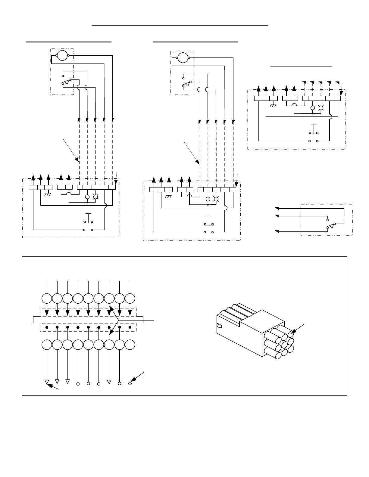
2. Prior to installation, make the necessary wire connections per the appropriate wiring diagram.
3. Proper operating voltage must be supplied to the strike if it is to function correctly. Voltage
at the strike must be within +/-10% of the required voltage listed on the strike label.
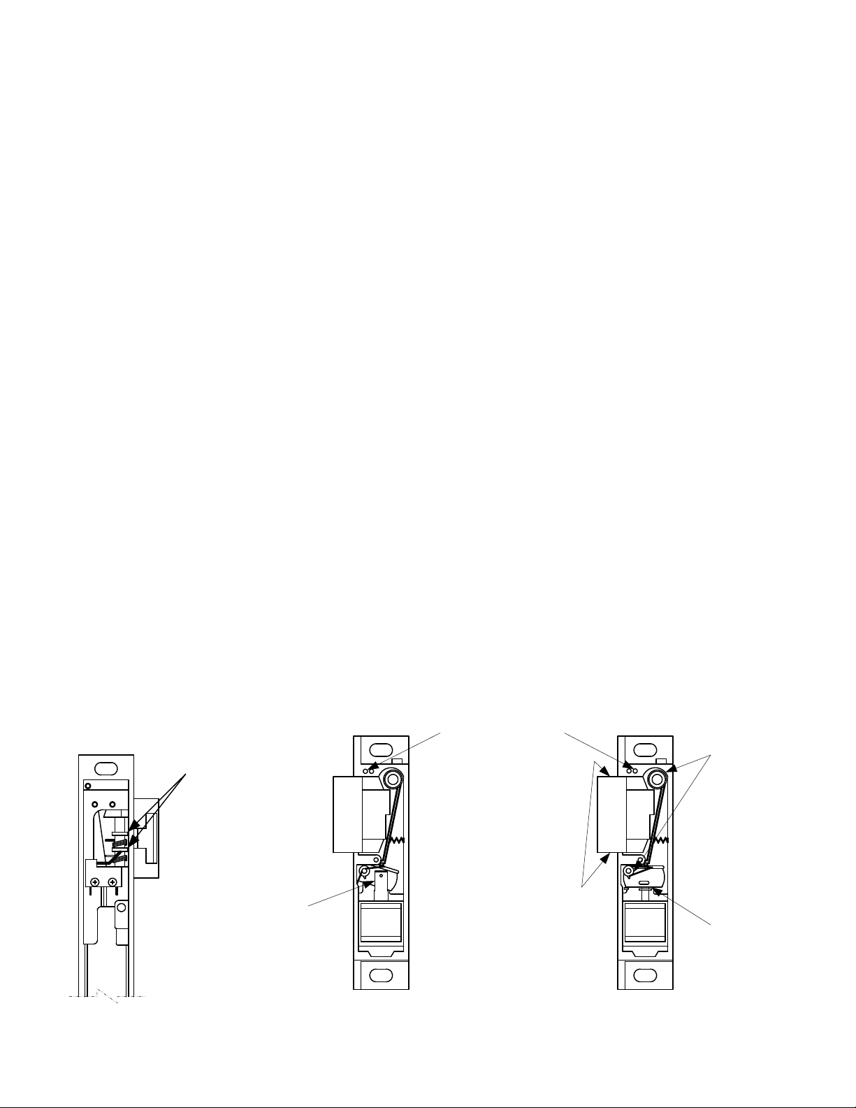
4. To install the strike into the frame opening:
A) Position the wiring either down, up or toward the back of the hollow metal frame,
making sure that it stays completely out of the way of the strike to avoid being pinched
during installation.
B) Mount the strike using the screws supplied.
5. After installation, check the horizontal alignment. Be certain that the centerline of the latch
bolt is aligned with the centerline of the strike.
6. In case of misalignment, there is a 3/16" horizontal adjustment between the strike
mechanism and the face plate. To adjust:
A) Remove mounting screws.
B) Remove strike from frame.
C) Loosen the two (2) #12-24 x 3/8” hex washer head cap screws.
D) Reposition strike and re-tighten cap screws.
OPERATION:
The SDC 30-4 Electric Strike is a solenoid operated device.
1. NON-FAIL SAFE
When power is applied the solenoid pulls the locking cam into the unlocked position
allowing the door to be opened. If power fails the strike will remain locked.
NOTE: Non-fail safe strikes for use in fire rated doors can only be operated by momentary
contact switching (energized only when the push button is held depressed) and can not
be held in the unlocked position.
2. FAIL SAFE:
When the power is applied the solenoid pushes the locking cam into the locked position
and the door can not be opened. If power fails the strike will unlock.
OPERATION NOTE: This product may be provided fail safe or non-fail safe. Fail safe versions
allow exit in the event of a power failure. Fail secure version do not.
Consult with the local authority having jurisdiction concerning the
installation of this type of product and whether listed panic hardware is
required to allow emergency exit from the secured area.
INSTALLATION INSTRUCTIONS
30-4 ELECTRIC STRIKE

P:\INSTALLATION INST\ELECTRIC STRIKE\INST-30-4.vsd Rev - 01/11 Page 2
OPTIONAL FEATURES;
1. LBM SWITCH (Latch Bolt Monitor) – A switch operated by the switch tripper that signals
whether or not the latch bolt is extended into the strike.
2. LCM SWITCH (Locking Cam Monitor) – A switch operated by the roll pin on the locking cam
that monitors the position of the locking cam and signals that the strike is either locked or
unlocked.
3. LCBM SWITCH (Locking Cam and Latch Bolt Monitor) – A switch operated by the LCM
switch tripper and the LBM switch tripper that signals that the strike is locked and the
latch bolt is engaged.
4. LCBMA SWITCH (Locking Cam and Latch Bolt Monitor, wired separately) – This is the same
as the LCBM with an additional switch operated by the LBM switch tripper.
5. KEEPERS – There is a standard type for each model 300 strike. Optional keepers are
available for some models.
6. SOLENOID VOLTAGE –24VDC is standard. Optional voltages available are: 12 or 115VDC,
6, 12, 24, 48 or 115VAC. NOTE: UL requires that a junction box be use with 48 and 120 volt
strikes if they are not installed in a back box.
7. SILENT OPERATION (SO) – Silent operation is recommended for AC non-fail safe strikes
that are to be energized for extended periods of time. All silent operation strikes are operated
by DC solenoids. When control power source is AC, the strike is supplied with an externally
attached bridge rectifier.
8. FAIL SAFE – The strike is locked when energized. This feature should be used for
applications that require automatic unlocking in case of power failure. All fail safe strikes are
operated by DC solenoids and are silent operation.
CAUTION: Fail safe is not permitted with the UL Fire Door Accessory label.
9. MOUNTING TAB – The mounting tab is designed to be used with the 30 series electric
strikes when mounting in metal frames.
10. ASTRAGAL - A lock guard designed to prevent tampering with the strike keeper and the
latch bolt.
INSTALLATION INSTRUCTIONS 30-4 ELECTRIC STRIKE

30-4 SERIES ELECTRIC STRIKE WIRING DIAGRAMS
Notice:
Wiring subject to change without
prior notice. Not responsible for
controls furnished by others.
Attachment of New Rectifier
(Required when supplying AC power
to a unit with a DC solenoid)
DC solenoid
Black/Yellow
Tracer
Brown
Terminal
Strip
Brown
Black/Yellow
Bridge
Rectifier
Rating:
2 Amps at ANY
Solenoid Voltage Y
YellowYellow
-
*
Attachment of Old Rectifier
(Required when supplying AC power
to a unit with a DC solenoid)
DC solenoid
Black/Yellow
Tracer
Yellow
Terminal
Strip
Yellow
Black
Bridge
Rectifier
Rating:
2 Amps at ANY
Solenoid Voltage Y
*
Red Yellow
Black
Red
Blue
Yellow
*
936 14
N/O
N/C C
Dotted Lines Represent
Field wires by others
+-Y
*
BR
+-
GND
RG
Push
Button N/C
N/O
Typical Control
Schematic for
Reference only
Lock Cam/Bolt
Monitor Switch
(Long Arm)
Control
Power
Indication
Power
Unlocked When Energized
Terminal
Strip
Black
Red
Blue
Yellow
*
936 14
N/O
N/C
C
Dotted Lines Represent
Field wires by others
+-Y
*
BR+ -
GND
RG
Push
Button N/C
N/O
Typical Control
Schematic for
Reference only
Lock Cam/Bolt
Monitor Switch
(Long Arm)
Control
Power
Indication
Power
Unlocked When Energized
Terminal
Strip
Push Button Switch Conditions
N/C
N/O
Lock N/C
N/O
Unlock
P:\INSTALLATION INST\ELECTRIC STRIKE\INST-30-4.vsd Rev - 01/11 Page 3
Solenoid Solenoid
30-4 Series LCBM
Wiring Diagram
30-4 Series LCBMA
Wiring Diagram
C
N/O
N/C
ORANGE
BROWN
PURPLE
Auxiliary
Switch
(LBM)
7
5
8
Electrical Ratings for
ALL 30-4
Electric Strike Solenoids
Resistance in OHMS +/- 10% 6.2 23.5 500 6.2 23.5 96.0 380 1200
Watts Seated 5.4 5.8 6.3 5.8 6.1 6.0 6.1 6.3
Amps Seated .45 .24 .06 .97 .51 .25 .13 .06
Amps Inrush 1.33 .69 .16 N/A N/A N/A N/A N/A
12 24 120 6 12 24 48 120
AC DC
VOLTAGE

P:\INSTALLATION INST\ELECTRIC STRIKE\INST-30-4.vsd Rev - 01/11 Page 4
30-4 ELECTRIC STRIKE WIRING DIAGRAMS
+-Y
*
BR
+-
GND
RG
Push
Button N/C
N/O
Typical Control
Schematic for
Reference only
Control
Power
Indication
Power
Locked When Energized
(Fail Safe) all 300 Strikes
Terminal
Strip
Fail Safe Controls
Grey
Orange
Purple
7
5
8
Auxiliary
Contacts
Optional DBS Switch
(not available with LCBMA)
Door shown closed and locked.
Dead Bolt Extended into Face Plate
NOTES:
1) = Wires color code
6 thru 120 VDC Yellow/Black Tracer
12 & 24 VAC-Grey
120 VAC-White
2) Unused wires to be individually isolated with a wire nut or equal.
3) Numbered field connections refer to pin location in field receptacle.
*
Brown
Orange
Purple
Yellow
*
758 14
N/O
N/C C
Dotted Lines Represent
Field wires by others
+-Y
*
BR+ -
GND
RG
Push
Button N/C
N/O
Typical Control
Schematic for
Reference only
Latch Bolt
Monitor Switch
Control
Power
Indication
Power
Unlocked When Energized
Terminal
Strip
30-4 LBM wiring diagram
Solenoid
30-4 LCM wiring diagram
Black
Red
Blue
Yellow
*
936 14
N/O
N/C C
Dotted Lines Represent
Field wires by others
+-Y
*
BR
+-
GND
RG
Push
Button N/C
N/O
Typical Control
Schematic for
Reference only
Latch Bolt
Monitor Switch
Control
Power
Indication
Power
Unlocked When Energized
Terminal
Strip
Solenoid
1
2
3
654
987
Optional 9-Pin Field Wiring Conn.
7 5 8 9 3 6 2 1
*
Strike Wires
758936214
GRY or
BRN
ORG
PUR
BLK
RED
BLU
YEL
YEL
WHT
Pin #2
Not Used
Field
Connector
Aux Contacts
Field
Receptacle
Pin
Location
Installation Must Be Properly Grounded
Per National Electrical Code Article 250

P:\INSTALLATION INST\ELECTRIC STRIKE\INST-30-4.vsd Rev - 01/11 Page 5
Under normal usage the 30-4 Electric Strike should be cleaned and lubricated once a year to maintain it’s reliability.
In applications with high usage or dirty conditions more frequent service may be necessary. Lubrication points are identified in
the illustration. When servicing the 30-4 Electric Strike, inspect the internal parts for excess wear or breakage and lightly
lubricate per instructions below. Lubricate with lightening grease available from SDC. Never lubricate any strike with oil!
Such lubrication collects dirt and forms an abrasive and sticky compound that may affect the function of the strike.
TO INSPECT AND LUBRICATE THE STRIKE;
1. Remove the strike from the face plate (held on by (2) #12-24 X 3/8” Hex Washer Head Cap SCREWS).
2. Remove the upper cover held on by (2) #4-40 X 3/16” PHMS. Removal of the upper cover should be done slowly because
the locking cam spring may snap out of place. Also, care should be taken to insure that the locking cam spacer and
locking lever spacer are not lost.
3. Remove the cam spring spacer, cam spring and locking lever spacer.
4. Loosen the (2) #6-32 X 1/8” SSSC holding the solenoid, then remove the solenoid and locking cam.
5. Remove the locking lever spring and locking lever. In some versions of the strike, there is a recess in the locking lever and
the case for this spring. In cases with the recess, the locking lever spring must be compressed into the lever before it can
be removed.
6. Lubricate the area in the case where the locking lever and locking cam rest (be careful not to get any lubricant on the
solenoid or switches). Lubricate the cam pin and lever pin.
7. Check the locking angle of the keeper and locking lever for wear. Replace the keeper and/or lever if worn (if the keeper
is disassembled for replacement or adding of a switch, lubricate the keeper pin).
8. Reinstall the locking lever and a new locking lever spring. CAUTION: Make sure the locking lever is placed back into the
recesses of the locking lever and the case.
9. Check the solenoid, plunger and plunger guide for excess wear, dirt, grime or oil. If present, wipe clean.
FAIL SAFE: Remove the retaining ring for inspection of the plunger guide. Reassemble the solenoid and plunger with
a new retaining ring.
NON-FAIL SAFE: Lubricate the bottom edge of the locking cam (contact point of the solenoid plunger).
10. NON-FAIL SAFE: Lubricate the slot in the locking cam
FAIL SAFE: Lubricate the bottom edge of the locking cam (contact point of the solenoid plunger).
MAINTENANCE AND LUBRICATION INSTRUCTIONS
Lightening grease
hubs where they
contact keeper
Rear view shown
with LCBM switch
Lightening grease
keeper pin
before assembly
Lightening grease
sides of keeper
before assembly
Lightening grease
cam slot and both
cam surfaces
between plunger
Front View
Non Fail Safe
Shown Unlocked
Front view
Fail Safe
Shown Locked
Lightening grease
pins and bottom
of case
Lightening grease
bottom of cam
and plunger pin

P:\INSTALLATION INST\ELECTRIC STRIKE\INST-30-4.vsd Rev - 01/11 Page 6
11. Installation and positioning of the solenoid.
NON-FAIL SAFE
1) Install the solenoid and locking cam assembly
2) Install the locking cam spring (with the long leg of the spring on the locking cam and the short leg in the
groove on the case).
3) Before tightening the set screws, energize the solenoid and check the position of the locking cam and locking lever.
4) Adjust the solenoid position to where the locking lever will clear the locking cam and tighten set screws.
FAIL SAFE
1) Install the solenoid and locking cam.
2) Install the locking cam spring (with the long leg of the spring on the locking cam and the short leg in the
groove on the case).
3) Before tightening the set screws, energize the solenoid and check the position of the locking cam.
4) Adjust the position of the solenoid to where it pushes the locking cam into the fully locked position (be careful not to
position the solenoid too high or the solenoid plunger will not seat).
5) De-energize and make sure the locking cam falls to a level to be unlocked. Tighten set screws.
12. Check all screws, tighten if necessary. CAUTION: Do not over tighten the switch screws. Over tightening could damage
the switch.
13. Reinstall the cam spring spacer and the locking lever spacer.
14. Reinstall the upper cover.
15. Reassemble the strike to the face plate.
MAINTENANCE AND LUBRICATION INSTRUCTIONS
Front View
Non Fail Safe
Shown Unlocked
Locked Position
Unlocked Position
Front View
Fail Safe
Shown Locked
Loosen set screws
to position solenoid.
Tighten after position
is set.
Table of contents
Other SDC Door Lock manuals

SDC
SDC E72 EntryCheck User manual

SDC
SDC E75 Series Operating instructions

SDC
SDC 352 Narrow Line EMLock User manual

SDC
SDC Z7500 Series User manual

SDC
SDC SK-82 User manual

SDC
SDC Z7835 Series User manual

SDC
SDC Z7700 Series User manual

SDC
SDC Z7835 User manual

SDC
SDC S6300 Series User manual

SDC
SDC E72K-A CIVIC SERIES Installation manual
Popular Door Lock manuals by other brands

ABH
ABH LR6000 Series installation instructions

Adel
Adel ST370 user manual

SCS Sentinel
SCS Sentinel XO 403 + CLES Installation and operation manual

SOREX
SOREX FLEX instruction manual

CODELOCKS
CODELOCKS KL1000 G3 NetCode Programming and operating instructions

Dormakaba
Dormakaba PowerPlex 2000 Series installation instructions