3.2 Testing the Lock Operation
To test ock operation before initia ization, enter *741. This temporary code wi un ock the E75 for verifying proper
hardware insta ation. NOTE: The ock wi un ock, but the Green LED wi not ight.
Once a ock initia ization has been performed, this code is no onger va id unti a factory reset is performed. A factory
reset wi erase a the users, ock settings, and return the E75 back into the uninitia ized factory defau t condition.
To Initialize the Lock: Press #9*123456#4-digit Lock ID#
Examp e: Press #9* 123456# 0001#
The above examp e enters a Lock ID of ‘0001’. If mu tip e ocks are used, it is mandatory that each ock have its
own Unique Lock ID (0002, 0003, etc.).
3.3 Lock Initialization
When the ock is first insta ed or after a factory reset has been performed, the E75 must be initia ized with a 4-digit
ock ID before you wi be a owed to enter programming mode. This step is required before using the E7
Management Software.
P:\INSTALLATI N INST\ACCESS C NTR LS\E75\INST-E7 SW Install Manual.vsd 10-14 Page 3
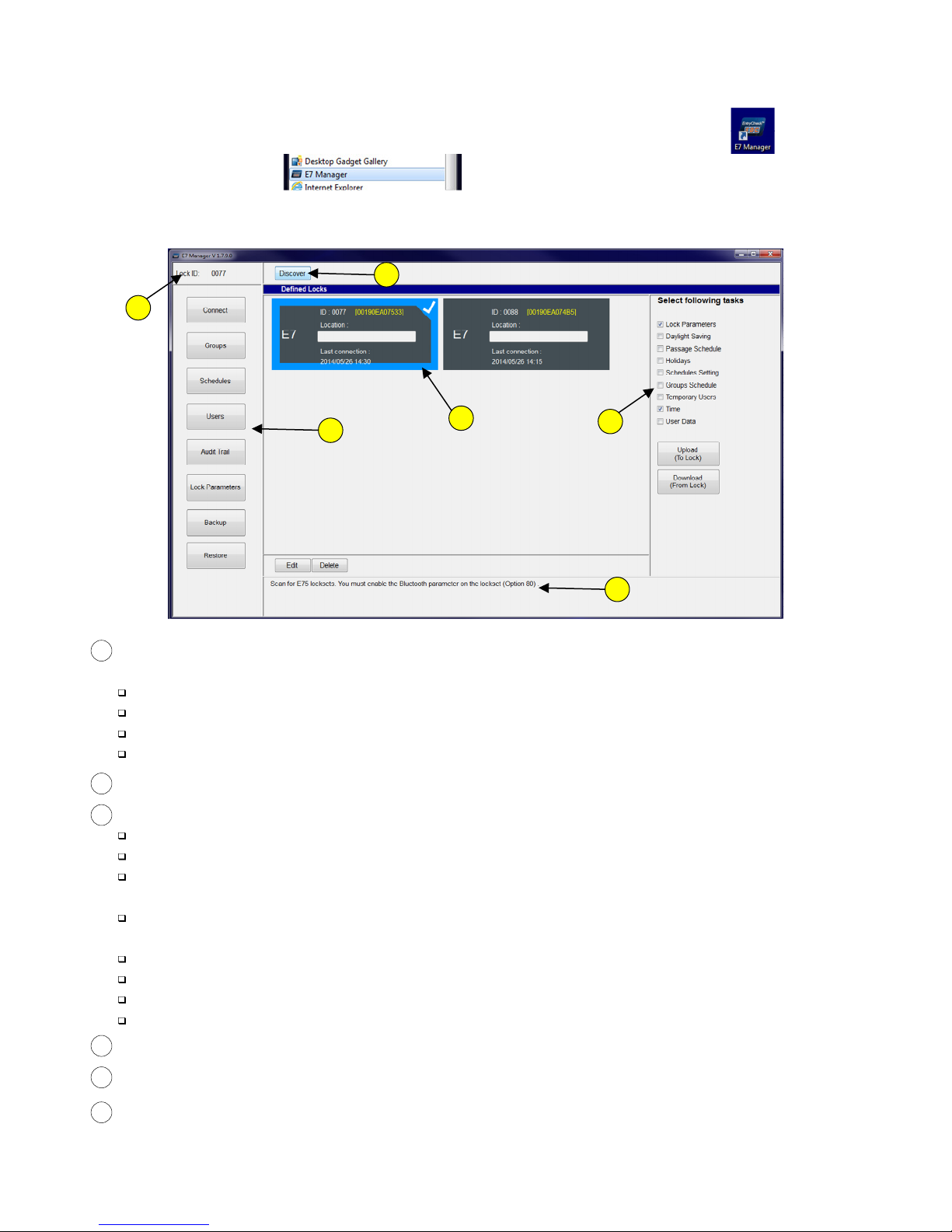
3.4 Entering and Exiting rogramming Mode
The E7 Management Software uti izes B uetooth communications to transfer data to & from a ock. You must first put
the ock into Programming Mode to enab e B uetooth. NOTE: Whi e in Programming Mode, the eftmost LED wi f ash
ye ow (once/sec). Twenty seconds of inactivity wi automatica y exit you from programming mode and return you to
operationa (standby) mode.
To Enter Programming Mode:
Examp e: Press #9# 01# 123456#
User 01 with defau t PIN Code 123456 is the Administrator and has fu programming rights. It is recommended that this PIN
Code be changed, as instructed in 3.6. NOTE: The User must be the Administrator or must be assigned to Groups 2-5 to have
programming rights.
Press #9# User No# User PIN Code #
To Exit Programming Mode: Press **#
Examp e: Press **#
3 0 Before You Start
3.1 LED & Audible Indicators
There are 2 LED indicators on the front face of the ock. The eftmost LED may i uminate RED, GREEN, or YELLOW.
The right LED wi on y i uminate BLUE.
Momentary GREEN
From Normal Operational (Standby) Mode,
Momentary RED
From Programming Mode,
= Whi e performing any Function, an intermediate step has been accepted
= In Programming Mode
F ashing YELLOW
= After each key press, or Access Granted
= Error
= Standby Mode, or Keypad Lockout
Both LEDs OFF
F ashing BLUE = B uetooth Enab ed
GRN LED+Beep (Simu taneous)
GRN LED+Beep (x2)
GRN LED+Beep, RED LED+Beep, GRN LED+Beep
= Function Successfu y Comp eted
= Entering Program Mode
YEL LED+Beep, Pause, GRN LED+Beep (x3) = Exiting Program Mode
A ternating RED/GRN LED, then 3 Beeps = On Lock Power Up
= Whi e performing any Function, waiting for user input
Both LEDs OFF