10
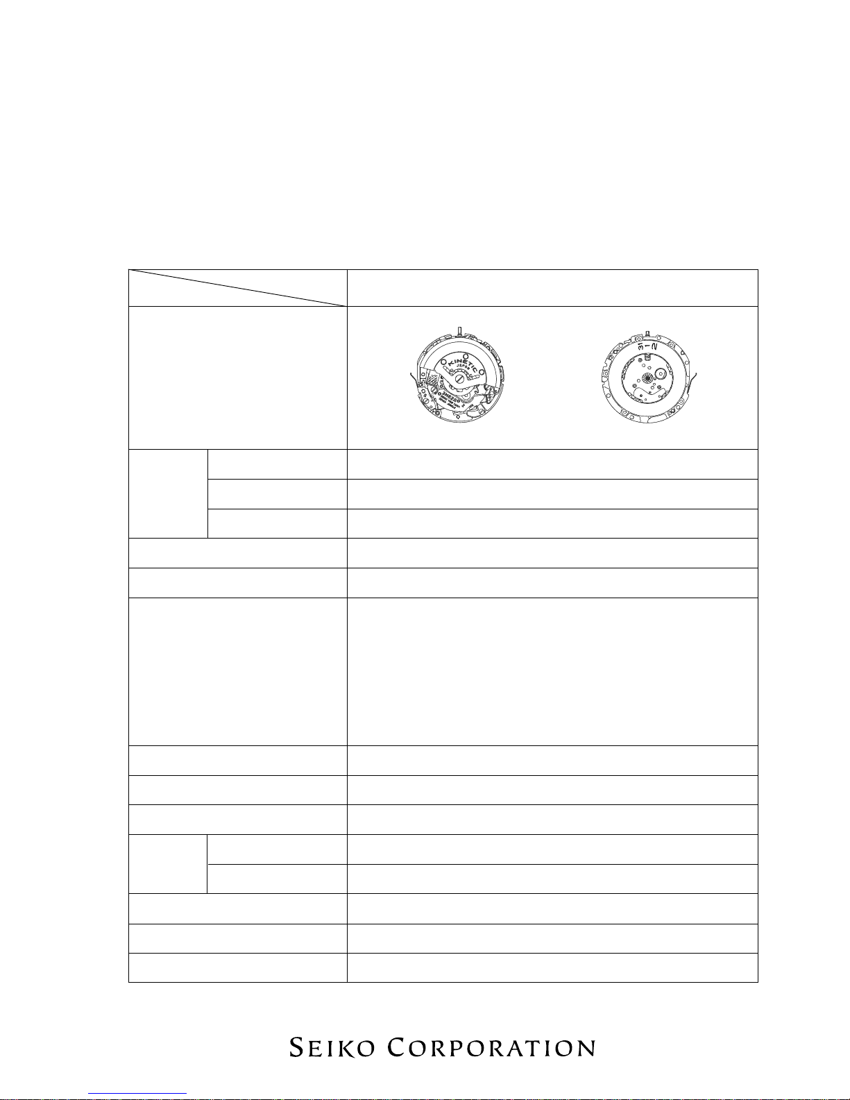
TECHNICAL GUIDE Cal. 3M62A
●Current consumption
For the whole movement : Less than 0.60 µA (with 1.55 V supplied from a battery)
For the circuit block alone : Less than 0.20 µA (with 1.55 V supplied from a battery)
1. Make the movement ready for measurement.
How to measure the current consumption for the whole movement
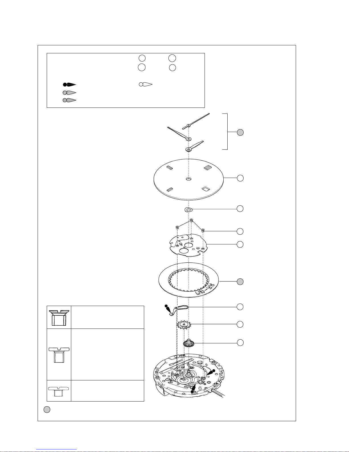
1) Follow the disassembling procedure
illustrated in this manual until you remove
the rechargeable battery unit.
2) Install the rechargeable battery clamp and
then tighten the screws “A” and “B” in the
illustration at right.
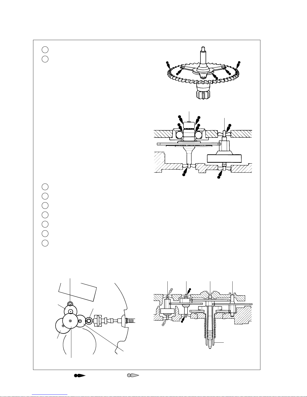
3) Install the oscillating weight wheel and
oscillating weight and then tighten the
oscillating weight screw.
As a result, the insulators A and B for
rechargeable battery, circuit block cover B
screw, circuit block cover B and
rechargeable battery unit are removed
from the movement. Screw “A”
Screw “B”
Rechargeable
battery clamp
Circuit board
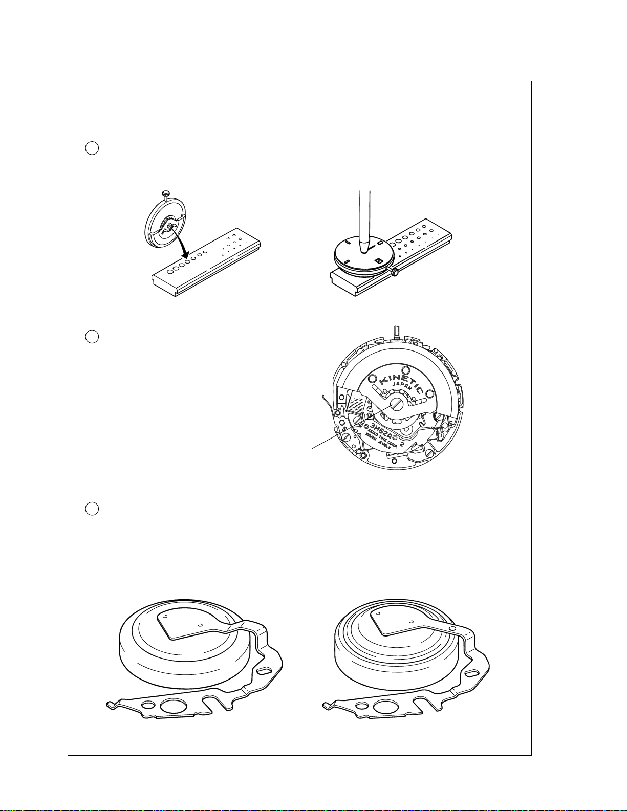
2. Apply the minus terminal to “a” portion of the
input terminal (–) in the illustration and plus
terminal to the rechargeable battery clamp,
respectively.
“a” portion of the input terminal (–)
Rechargeable battery clamp
Note: When moving the oscillating weight
from side to side, take care lest the
minus terminal of the tester touches the
oscillating weight.
3. For a few seconds after the probes of the tester
are applied to the movement, the IC is in the
quick start mode, and current consumption
cannotbe measured properly. To switch the IC
from the quick start to the normal hand
movement mode, move the oscillating weight
from side to side continuously for more than
three seconds with the tester connected to the
movement. The IC will detect the electricity
generation and will be switched to the normal
hand movement mode.
4. After checking that the IC has been switched to the normal hand movement mode and a stable
measurement can be obtained, read the measurement.
If the measurement value remains high or unstable, repeat step “3” above.