manuals.online logo
Brands
  1. Home
  2. •
  3. Brands
  4. •
  5. Sensopart
  6. •
  7. Accessories
  8. •
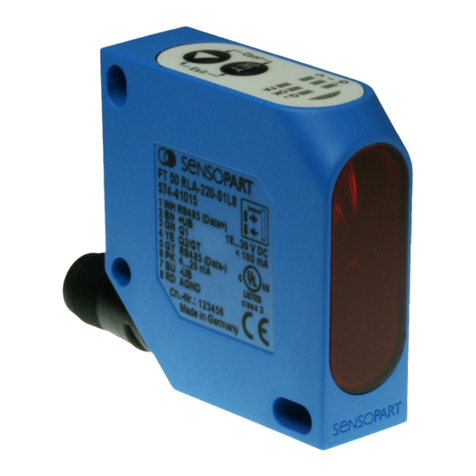
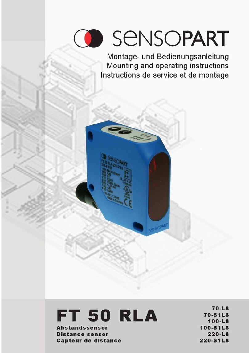
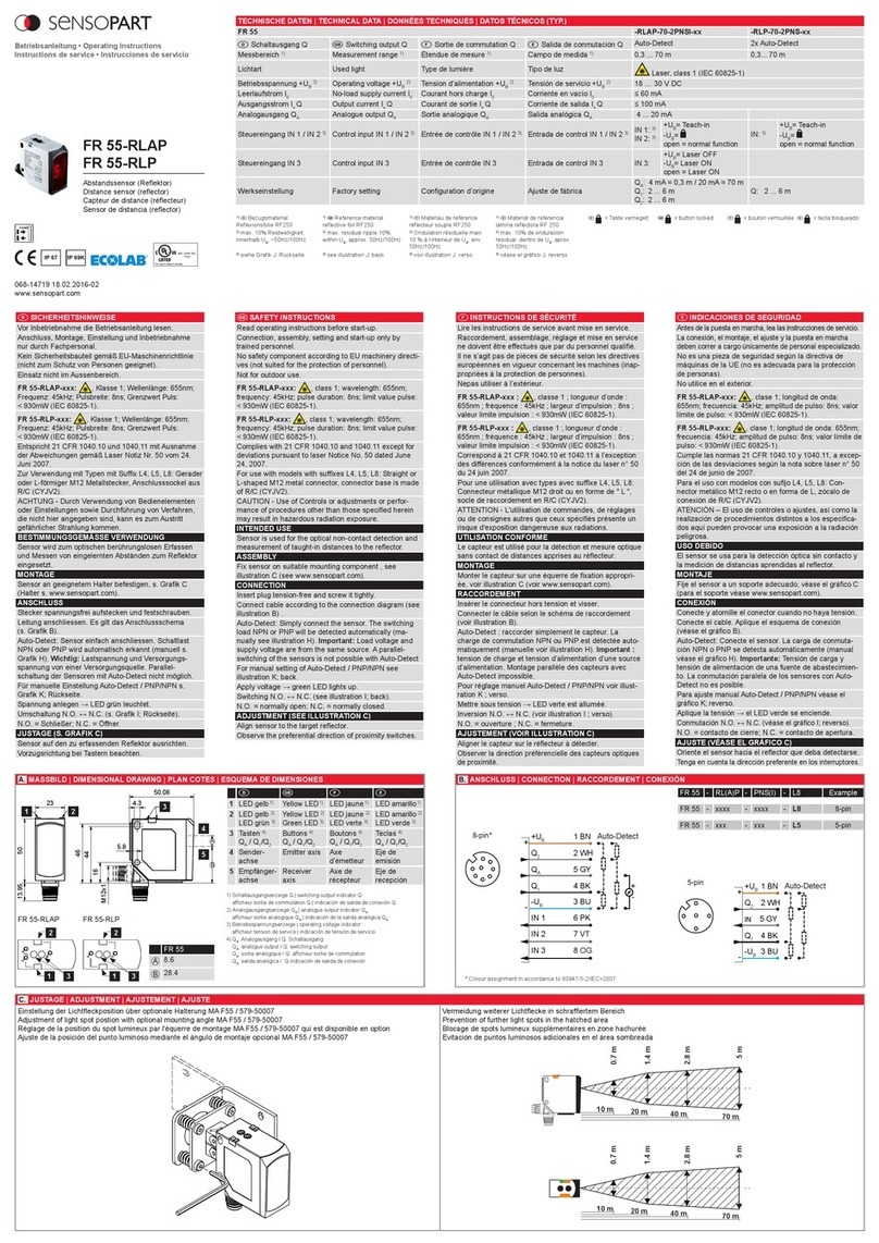
  9. Sensopart FT 55-RLHM User manual

Sensopart FT 55-RLHM User manual

1
SAFETY INSTRUCTIONS
Read operating instructions before start-up.
Connection, assembly, setting and start-up only by
trained personnel.
No safety component according to EU machinery
directives (not suited for the protection of personnel).
Not for outdoor use.
FT 55-RLHM-xxx: , class 1; wavelength: 655 nm;
frequency: 5.4 kHz; pulse duration: 8 µs; (IEC 60825-1).
Complies with 21 CFR 1040.10 and 1040.11 except for
deviations pursuant to laser Notice No. 50 dated June
24, 2007.
For use with models with su󰀩xes L5: Straight or
L-shaped M12 metal connector, connector base is made
of R/C (CYJV2).
CAUTION - Use of controls or adjustments or perfor-
mance of procedures other than those specied herein
may result in hazardous radiation exposure.
INTENDED USE
Sensor is used for the optical non-contact detection of
objects.
ASSEMBLY
Fix sensor on suitable mounting component
(bracket see www.sensopart.com).
CONNECTION
Insert plug voltage-free and screw it tightly.
Connect cable according to the connection diagram (see
illustration B).
Auto-Detect: Simply connect the sensor. The switching
load NPN or PNP will be detected automatically.
Important: Load voltage and supply voltage are from the
same source. A parallel switching of the sensors is not
possible with Auto-Detect.
Apply voltage → green LED lights up
(Exception Layer Detection mode).
Switching N.O. ↔ N.C. via display or IO-Link.
IO-Link Communication → green LED ashes
(Exception Layer Detection mode).
ADJUSTMENT (SEE ILLUSTRATION C)
Align sensor to the target object.
Observe the preferential direction (see illustration C).
MAINTENANCE
SENSOPART sensors are maintenance-free. We recom-
mend to cyclically clean the optical surfaces and check
the screw connections and plug connections.
FT 55-RLHM
Laser-Reexionslichttaster
Di󰀨use laser sensor
Détecteur de proximité laser
Interruptor de proximidad láser
Betriebsanleitung • Operating instructions
Instructions de service • Instrucciones de servicio
068-14886 03.06.2020-01
www.sensopart.com
D  F E
1LED gelb
1)
Yellow LED
1) LED jaune
1) LED amarillo 1)
2LED gelb
2)
LED grün 3)
Yellow LED
2)
Green LED
3)
LED jaune
2)
LED verte 3)
LED amarillo 2)
LED verde 3)
3Tasten Buttons Boutons Teclas
4Empfänger-
achse
Receiver
axis
Axe de
récepteur
Eje de
recepción
5Sender-
achse
Emitter axis Axe
d’émetteur
Eje de
emisión
1) Schaltausgangsanzeige Q1| switching output indicator Q1
a󰀩cheur sortie de commutation Q1| indicación de salida de conexión Q1
2) Schaltausgangsanzeige Q2| switching output indicator Q2
a󰀩cheur sortie de commutation Q2| indicación de salida de conexión Q2
3) Betriebsspannungsanzeige | operating voltage indicator
a󰀩cheur tension de service | indicación de tensión de servicio
-600- / - 1000-
A23,75
B7,45
TECHNISCHE DATEN (TYP.) | TECHNICAL DATA (TYP.) | DONNÉES TECHNIQUES (TYP.) | DATOS TÉCNICOS (TYP.)
FT 55-RLHM-xxx-2PNSDL-L5M -600- -1000-
DSchaltausgang Q Switching output Q FSortie de commutation Q ESalida de conmutación Q Auto-Detect I PNP I NPN I Push-Pull
Tastweite (TW) 1) Scanning distance (TW) 1) Distance de détection (TW) 1) Distancia de detección (TW) 1) 120 ... 600 mm
0 ... 600 mm Detect All-Modus
200 ... 1000 mm
0 ... 1000 mm Detect All-Modus
Schalthysterese
(einstellbar)
Switching hysteresis
(adjustable)
Hystérésis de commutation
(réglable)
Conmutación de histéresis
(ajustable) 1,2 mm 2 mm
Lichtart Used light Type de lumière Tipo de luz Laser, class 1 (IEC 60825-1)
Betriebsspannung +UB2) Operating voltage +UB2) Tension d’alimentation +UB2) Tensión de servicio +UB2) 15 … 30 V DC
Leistungsaufnahme Power consumption Consommation Consumo de potencia ≤ 1,5 W
Ausgangsstrom Ie Q Output current Ie Q Courant de sortie Ie Q Corriente de salida Ie Q≤50 mA
Werkseinstellung Q1 / Q2Factory setting Q1 / Q2Conguration d’origine Q1 / Q2Ajuste de fábric Q1 / Q2600 mm 1000 mm
1) DBezugsmaterial grau,
18 % Remission
1) Reference material grey,
18 % reectance
1) F Matériau de référence gris, 18
% réexion
1) E Material de referencia gris,
18 % de reexión
2) max. 10 % Restwelligkeit,
innerhalb UB, ~50 Hz/100 Hz
2) max. residual ripple 10 %,
within UB, approx. 50 Hz/100 Hz
2) Ondulation résiduelle maxi 10 % à
l’intérieur de UB, env. 50 Hz/100 Hz
2) máx. 10 % de ondulación residual,
dentro de UB, aprox. 50 Hz/100 Hz
3Display
1
2
4
5
25
50.5
17
4.3
50
4
16
44
46
12M x1
A
B
Keep any button pressed and Power ON > 10 s
green LED OFF green LED ashes
until both yellow LEDs ash 3x at the same time
Power OFF
green LED OFF
press any button
Power OFF Power ON
 
IP 69
Data sheet and IODD IO-Link available at www.sensopart.com/de/download
DSICHERHEITSHINWEISE
Vor Inbetriebnahme die Betriebsanleitung lesen.
Anschluss, Montage, Einstellung und Inbetriebnahme
nur durch Fachpersonal.
Kein Sicherheitsbauteil gemäß EU-Maschinenrichtlinie
(nicht zum Schutz von Personen geeignet).
Einsatz nicht im Außenbereich.
FT 55-RLHM-xxx: , Klasse 1; Wellenlänge: 655 nm;
Frequenz: 5,4 kHz; Pulsbreite: 8 µs; (IEC 60825-1).
Entspricht 21 CFR 1040.10 und 1040.11 mit Ausnahme
der Abweichungen gemäß Laser-Notiz Nr. 50 vom 24.
Juni 2007.
Zur Verwendung mit Typen mit Su󰀩x L5: Gerader oder
L-förmiger M12 Metallstecker, Anschlusssockel aus R/C
(CYJV2).
ACHTUNG - Durch Verwendung von Bedienelementen
oder Einstellungen sowie Durchführung von Verfahren,
die nicht hier angegeben sind, kann es zum Austritt
gefährlicher Strahlung kommen.
BESTIMMUNGSGEMÄSSE VERWENDUNG
Sensor wird zum optischen berührungslosen Erfassen
von Objekten eingesetzt.
MONTAGE
Sensor an geeignetem Halter befestigen
(Halter s. www.sensopart.com).
ANSCHLUSS
Stecker spannungsfrei aufstecken und festschrauben.
Leitung anschließen. Es gilt das Anschlussschema
(s. Grak B).
Auto-Detect: Sensor einfach anschließen. Schaltlast
NPN oder PNP wird automatisch erkannt. Wichtig:
Lastspannung und Versorgungsspannung von einer
Versorgungsquelle. Parallelschaltung der Sensoren mit
Auto-Detect nicht möglich.
Spannung anlegen → grüne LED leuchtet
(Ausnahme Layer Detection-Modus).
Umschaltung N.O. ↔ N.C. über Display oder IO-Link.
IO-Link Kommunikation → grüne LED blinkt
(Ausnahme Layer Detection-Modus).
JUSTAGE (S. GRAFIK C)
Sensor auf das zu erfassende Objekt ausrichten.
Vorzugsrichtung beachten (siehe Grak C).
WARTUNG
SENSOPART-Sensoren sind wartungsfrei. Es wird
empfohlen in regelmäßigen Intervallen die optischen
Flächen zu reinigen und Verschraubungen und Steck-
verbindungen zu überprüfen.
FINSTRUCTIONS DE SÉCURITÉ
Lire les instructions de service avant mise en service.
Raccordement, assemblage, réglage et mise en service
ne doivent être e󰀨ectués que par du personnel qualié.
Il ne s’agit pas de pièces de sécurité selon les directives
européennes en vigueur concernant les machines (inap-
propriées à la protection de personnes).
Ne pas utiliser à l’extérieur.
FT 55-RLHM-xxx : , classe 1 ; longueur d’onde :
655 nm ; fréquence : 5,4 kHz ; largeur d’impulsion :
8 µs ; (IEC 60825-1).
Correspond à 21 CFR 1040.10 et 1040.11 à l’exception
des di󰀨érences conformément à la notice du laser n° 50
du 24 juin 2007.
Pour une utilisation avec types avec su󰀩xe L5 :
Connecteur métallique M12 droit ou en forme de " L ",
socle de raccordement en R/C (CYJV2).
ATTENTION - L'utilisation de commandes, de réglages
ou de consignes autres que ceux spéciés présente un
risque d'exposition dangereuse aux radiations.
UTILISATION CONFORME
Le capteur est utilisé pour la détection optique des objets
sans contact.
MONTAGE
Monter le capteur sur une équerre de xation appropriée
(voir www.sensopart.com).
RACCORDEMENT
Insérer le connecteur hors tension et visser.
Connecter le câble selon le schéma de raccordement
(voir illustration B).
Auto-Detect: raccorder simplement le capteur. La charge
de commutation NPN ou PNP est détectée automa-
tiquement. Important : tension de charge et tension
d’alimentation d’une source d’alimentation. Montage
parallèle des capteurs impossible avec Auto-Detect.
Mettre sous tension → LED verte est allumée
(Exception mode Layer Detection).
Inversion N.O. ↔ N.C. via écran ou IO-Link.
Communication IO-Link → LED verte clignote
(Exception mode Layer Detection).
AJUSTEMENT (VOIR ILLUSTRATION C)
Aligner le capteur sur l’objet à détecter.
Observer la direction préférencielle
(voir illustration C)
.
ENTRETIEN
Les capteurs SENSOPART ne demandent aucun
entretien. Nous recommandons de nettoyer les surfaces
optiques et vérier les raccordements et les xations
régulièrement.
EINDICACIONES DE SEGURIDAD
Antes de la puesta en marcha, lea las instrucciones de servicio.
La conexión, el montaje, el ajuste y la puesta en marcha
deben correr a cargo únicamente de personal especializado.
No es una pieza de seguridad según la directiva de
máquinas de la UE (no es adecuada para la protección
de personas).
No utilice en el exterior.
FT 55-RLHM-xxx: , clase 1; longitud de onda:
655 nm; frecuencia: 5,4 kHz; amplitud de pulso: 8 µs;
(IEC 60825-1).
Cumple las normas 21 CFR 1040.10 y 1040.11, a excep-
ción de las desviaciones según la nota sobre láser n° 50
del 24 de junio de 2007.
Para el uso con modelos con sujo L5: Connector
metálico M12 recto o en forma de L, zócalo de conexión
de R/C (CYJV2).
ATENCIÓN – El uso de controles o ajustes, así como la
realización de procedimientos distintos a los especica-
dos aquí pueden provocar una exposición a la radiación
peligrosa.
USO DEBIDO
El sensor se usa para la detección óptica sin contacto
de objetos.
MONTAJE
Fije el sensor a un soporte adecuado (para el soporte
véase www.sensopart.com).
CONEXIÓN
Conecte y atornille el conector cuando no haya tensión.
Conecte el cable. Aplique el esquema de conexión
(véase el gráco B).
Auto-Detect: Conecte el sensor. La carga de conmutaci-
ón NPN o PNP se detecta automáticamente.
Importante: Tensión de carga y tensión de alimentación
de una fuente de abastecimiento. La conmutación paral-
ela de los sensores con Auto-Detect no es posible.
Aplique la tensión → el LED verde se enciende
(Modo de detección de la capa de excepción).
Conmutación N.O. ↔ N.C. via display o IO-Link.
Comunicación IO-Link → el LED verde se parpadea
(Modo de detección de la capa de excepción).
AJUSTE (VÉASE EL GRÁFICO C)
Oriente el sensor hacia el objeto que deba detectarse.
Tenga en cuenta la dirección preferente
(véase el gráco C)
.
MANTENIMIENTO
Los sensores SENSOPART no necesitan manteni-
miento. Se recomienda limpiar las supercies ópticas a
intervalos regulares y comprobar las uniones atornilla-
das y conexiones.
1) Im IO-Link-Betrieb muss ein 4-poliges Kabel verwendet werden
In IO-Link mode, a 4-pin cable must be used
En mode IO-Link, un câble à 4 pôles doit être utilise
En modo IO-Link se debe utilizar un cable de 4 polos
5-pin
5
2
1
4
3
1)
-UB3 BU
Q1/IO-Link 4 BK
IN 5 GY
-
+UB
Q2
1
2
BN
WH
+Auto-Detect

10-30°
x x
 
 
B. ANSCHLUSS | CONNECTION | RACCORDEMENT | CONEXIÓNA. MASSBILD | DIMENSIONAL DRAWING | PLAN COTES | ESQUEMA DE DIMENSIONES
D. WERKSEINSTELLUNG | FACTORY SETTING | CONFIGURATION D'ORIGINE | AJUSTE DE FÁBRICAC. JUSTAGE | ADJUSTMENT | AJUSTEMENT | AJUSTE
Detect All-Modus (Distance + Intensity)
2
068-14886 03.06.2020-01
Menu
Cong Q1 OK

1)
SP1 (1000)
Hyst size
xxx mm
Live: xxx mm
Switchpoint
SET
OK
OKOK
SET
1) Änderung der Hysterese im Layer Detection-Modus erfordert erneutes Einlernen
*N.O.*
N.C.
N.O. / N.C. OK
SET
On delay
O󰀨 delay
Impulse
Counter
0 ms I 20 ms I 50 ms I 100 ms I Custom
OK
SmartFunc

OK
OK
SET
*Autodetect* I PNP I NPN I PushPull
OK
PNP / NPN
SET
*Distance*
Dist+Intens
OKDetectMode
SET
2) Nur Detect All-Modus
2)
Cong Q2 OK

1)
SP1 (1000)
Hyst size
xxx mm
Live: xxx mm
Switchpoint
SET
OK
OKOK
SET
1) Änderung der Hysterese im Layer Detection-Modus erfordert erneutes Einlernen
*N.O.*
N.C.
N.O. / N.C. OK
SET
On delay
O󰀨 delay
Impulse
Counter
0 ms I 20 ms I 50 ms I 100 ms I Custom
OK
SmartFunc

OK
OK
SET
*Autodetect* I PNP I NPN I PushPull
OK
PNP / NPN
SET
*Distance*
Dist+Intens
OKDetectMode
SET
2) Nur Detect All-Modus
2)
Cong In OK
Settings OK Yes
*No*
Factory set OK
SET
*1000 Hz* I 200 Hz I 100 Hz I 40 Hz I 20 Hz I 10 HzSpeed OK
SET
OK
Turn display
Screensave
LED Scheme3)
OKDisplay
On I *O󰀨*
Q output I Layer
SET
3) Nur Layer Detection-Modus
OK
Password OK
Password
set
1
2
00
1
2


On I *O󰀨*
SET
(Device name) I (Part number) I (Software version)
OK
Info
BACK
*Teach In* I Disabled I Laser I Key lock
SET
Betriebsmodi
TP = Teachpunkt
SP = Schaltpunkt
Hyst. = Hysterese Objekt = I Hintergrund =
Single Point-Modus
Window-Modus
Two Point-Modus
Detect All-Modus
Layer Detection-Modus
Teach display o󰀨set Yes → Display = 0 mm / + ... mm / - ... mm
No → Display = realer Abstandswert
Good Target
Bei aktivierter Funktion ist Q1 ON, wenn sich ein Objekt im Arbeitsbereich bendet und die
Signalqualität ausreichend ist.
Antivalent
Bei aktivierter Funktion wird die Ö󰀨ner- (N.C.) und Schließer- (N.O.) funktion gleichzeitig zur
Verfügung gestellt.
Beispiel Q1 N.O.:
Beispiel Q2 N.C.:
Einstellungen (Settings)
Werkseinstellung
(Factory set)
Löscht alle gespeicherten Werte und setzt den Sensor auf die Werksein-
stellungen zurück.
Display
(Display)
Display drehen
(Turn display)
Display wird um 180° gedreht.
Bildschirm-
schoner
(Screensave)
ON = Display geht nach 1 Minute aus und wird gesperrt.
OFF = Display bleibt an.
LED-Schema
(LED scheme)
Q output Blinkverhalten der LEDs entspricht dem Schaltverhalten
der Schaltausgänge (s. Grak G).
Layer
Blinkverhalten der LEDs entspricht Anzahl der Schich-
ten (s. Grak G). Aktualisierungszeit der LEDs ist nicht
zyklustreu.
Passwort
(Password)
Denition des Passwortes. Dieses muss jedes Mal, wenn der Sensor
entsperrt werden soll, eingegeben werden. Wenn das Passwort vergessen
wird, kann über den SensoPart Support ein Master-Passwort angefordert
werden.
Cong In
Eingangsfunktionen (In functions)
Laser o󰀨 +UB = Laser ein -UB = Laser aus
Key lock +UB = Tasten gesperrt -UB = Tasten zugänglich
Teach in
Q1: 3 s + 1 s TP1 / TP2
Q2: 6 s + 1 s TP1 / TP2
N.O./N.C./antivalent: 10 s + 1 s; akzeptiert, wenn 10 s keine Aktion 4) (s. Grak E)
NPN/PNP/Auto: 13 s + 1 s; akzeptiert, wenn 10 s keine Aktion 4) (s. Grak F)
4) Umschaltung wirkt auf beide Ausgänge
Schaltausgang Q1 / Q2 kongurieren (Cong Q1 / Cong Q2)
Smart functions (SmartFunc)
Anzugsver
-
zögerung
(On delay)
H
L
H
LDelay
Input
Output
einstellbar
in
1 ms
Schritten
Abfallverzö-
gerung
(O󰀨 delay)
H
L
H
L
Input
Output Delay
einstellbar
in
1 ms
Schritten
Impuls
(Impulse) H
L
H
L
Input
Output
Impulse
einstellbar
in
1 ms
Schritten
Zähler
(Counter) 1234123412
H
L
H
L
Input
Output
Objekt/Objekt Teach:
TP1=TP2=SP1
N.O. Hyst.
120/200
mm 600/1000
mm
TP1
N.O.
Objekt/Hintergrund Teach: TP250% 50 %SP
120/200
mm 600/1000
mm
Hyst.
Hysterese einstellbar Fein I Klein I Standard I Groß
TP1=SP1 TP2=SP2
N.O. Hyst.Hyst.
120/200
mm 600/1000
mm
Hysterese einstellbar Fein I Klein I Standard I Groß
120/200
mm 600/1000
mm
TP1 SP2SP1
Hyst.Hyst.
Keine
Blindzone
N.C.
Hyst.
Hyst.
TP nah
Teach O󰀨set
(Sollwert) TP fernSP1 SP2
Hyst.
"+ ... mm" "- ... mm"
"0 mm"
120/200
mm 600/1000
mm
N.C.
120/200
mm 600/1000
mm
N.O. Hyst.
TP1=SP1 TP2=SP2
Keine Auswirkungen der Hysterese-Einstellungen auf Einstellungen des Schaltpunktes;
Schaltpunkte denieren die Größe der Hysterese
SinglePoint
okcanc
Teach Q1 - SP
Teach on
object
set

Set Q1 - SP
xxx mm
Live: xxx mm
Teach Q1 - SP
Conrm obj. or
teach backgr.
canc ok
Window Q1 - WIN - SP1
Teach on close
switchpoint
okcanc set

xxx mm
Live: xxx mm
Q1 - WIN - SP1
set

Q1 - WIN - SP2
xxx mm
Live: xxx mm
Q1 - WIN - SP2
Teach on far
switchpoint
ok
canc
TwoPoint Q1 - 2Po - SP1
Teach on close
switchpoint
okcanc
xxx mm
Live: xxx mm
Q1 - 2Po - SP1
set

set

Q1 - 2Po - SP2
xxx mm
Live: xxx mm
Q1 - 2Po - SP2
Teach on far
switchpoint
okcanc
DetectAll Teach Q1 - DAM
Teach on
background
start
canc
Distance
Detect Mode
Dist+Intens
setcanc

Set Q1 - DAM
xxx mm
Live: xxx mm
set

LayerDtct Enter LayerDtct
LayerDtct
a󰀨ects
Q1 + Q2
okcanc
O󰀨set LDM
Teach display
o󰀨set?
yes nocanc
Teach LDM
Close distance
Q1
okcanc set

Set far LDM
xxx mm
Live: xxx mm
Teach LDM
Far distance
Q2
canc ok
set

Set close LDM
xxx mm
Live: xxx mm
xxx mm
Live: xxx mm
O󰀨set LDM
set

GoodTrgt
set
GoodTrgt
Set Q1 as
Good target
canc
only Q1
Antivalent Antivalent
Set Q2 as
Antivalent
setcanc
only Q2
OK OK
SET
OK OK
YES SET SET
OK
OK OK
STOPSET
OK SET OK
NO
FT 55-RLHM
entsperren 3 s 2 - service view 1 3 - service view 2
Q1
Teach Q1 / Q2
Q2
okback

1000
teachmenu



1000

freigeschaltet
Press Press
Press


Q1
Q2
SinglePoint
Teach Q1
Window
TwoPoint
setcanc

OK
SET
SET
Q1 SP Dist
Q2 SP Dist

IN Teach In
1 - main view
Press teach
Änderungen vorbehalten | subject to change | sous réserve de modications | salvo modicaciónwww.sensopart.com
D
*xxx* Werkseinstellungen
3
068-14886 03.06.2020-01
Cong Q1 OK

1)
SP1 (1000)
Hyst size
xxx mm
Live: xxx mm
Switchpoint
SET
OK
OKOK
SET
1) Change of the hysteresis in Layer Detection mode layer requires new teach-in
*N.O.*
N.C.
N.O. / N.C. OK
SET
On delay
O󰀨 delay
Impulse
Counter
0 ms I 20 ms I 50 ms I 100 ms I Custom
OK
SmartFunc

OK
OK
SET
*Autodetect* I PNP I NPN I PushPull
OK
PNP / NPN
SET
*Distance*
Dist+Intens
OKDetectMode
SET
2) Only Detect-All Mode
2)
Cong Q2 OK

1)
SP1 (1000)
Hyst size
xxx mm
Live: xxx mm
Switchpoint
SET
OK
OKOK
SET
1) Change of the hysteresis in Layer Detection mode layer requires new teach-in
*N.O.*
N.C.
N.O. / N.C. OK
SET
On delay
O󰀨 delay
Impulse
Counter
0 ms I 20 ms I 50 ms I 100 ms I Custom
OK
SmartFunc

OK
OK
SET
*Autodetect* I PNP I NPN I PushPull
OK
PNP / NPN
SET
*Distance*
Dist+Intens
OKDetectMode
SET
2) Only Detect-All Mode
2)
Cong In OK
Settings OK Yes
*No*
Factory set OK
SET
*1000 Hz* I 200 Hz I 100 Hz I 40 Hz I 20 Hz I 10 HzSpeed OK
SET
OK
Turn display
Screensave
LED Scheme3)
OKDisplay
On I *O󰀨*
Q output I Layer
SET
3) Only Layer-Detection Mode
OK
Password OK
Password
set
1
2
00
1
2


On I *O󰀨*
SET
(Device name) I (Part number) I (Software version)
OK
Info
BACK
*Teach In* I Disabled I Laser I Key lock
SET
Menu
Operation modes
TP = Teach point
SP = Switchpoint
Hyst. = Hysteresis Object = I Background =
Single-Point Mode
Window Mode
Two-Point Mode
Detect-All Mode
Layer-Detection Mode
Teach display o󰀨set Yes → Display = 0 mm / + ... mm / - ... mm
No → Display = real distance
Good Target
If activated, Q1 is ON whenever an object is within the working range and the signal quality is
su󰀩cient.
Antivalent
If activated, N.C. and N.O. function are available at the same time.
Example Q1 N.O.:
Example Q2 N.C.:
Settings
Factory set Deletes all modications that are done since set up of the sensor, all
settings are reset to original factory settings.
Display
Turn display Display is turned 180°.
Screensave ON = Display turns o󰀨 after 1 minute and gets locked.
OFF = Display stays onn.
LED scheme
Q output LED ashing behaviour corresponds to the switching
behaviour of the switching outputs (s. illustration G).
Layer
LED ashing behaviour corresponds to the number of
layers (s. illustration G). LED updating time is not true to
cycle.
Password
Denition of unlock password. This has to be entered each time when
unlocking the sensors. If password is forgotten, a master password can be
obtained at the SensoPart support.
Cong In
In functions
Laser o󰀨 +UB = Laser on -UB = Laser o󰀨
Key lock +UB = Keys are lock -UB = Keys are unlocked
Teach in
Q1: 3 s + 1 s TP1 / TP2
Q2: 6 s + 1 s TP1 / TP2
N.O./N.C./antivalent: 10 s + 1 s; accepted if no action for 10 s 4) (s. illustration E)
NPN/PNP/Auto: 13 s + 1 s; accepted if no action for 10 s 4) (s. illustration F)
4) Switching a󰀨ects both outputs
Cong Q1 / Cong Q2
Smart functions (SmartFunc)
On delay H
L
H
LDelay
Input
Output
adjustable
in
1 ms steps
O󰀨 delay H
L
H
L
Input
Output Delay
adjustable
in
1 ms steps
Impulse H
L
H
L
Input
Output
Impulse
adjustable
in
1 ms steps
Counter 1234123412
H
L
H
L
Input
Output
Object/Object teach:
TP1=TP2=SP1
N.O. Hyst.
120/200
mm 600/1000
mm
TP1
N.O.
Object/Background teach: TP250% 50 %SP
120/200
mm 600/1000
mm
Hyst.
Hysteresis adjustable Small I Medium I Standard I Wide
TP1=SP1 TP2=SP2
N.O. Hyst.Hyst.
120/200
mm 600/1000
mm
Hysteresis adjustable Small I Medium I Standard I Wide
120/200
mm 600/1000
mm
TP1 SP2SP1
Hyst.Hyst.
No blind
zone
N.C.
Hyst.
Hyst.
TP nah
Teach o󰀨set
(set value) TP fernSP1 SP2
Hyst.
"+ ... mm" "- ... mm"
"0 mm"
120/200
mm 600/1000
mm
N.C.
120/200
mm 600/1000
mm
N.O. Hyst.
TP1=SP1 TP2=SP2
Hysteresis settings do not inuence the switching point settings; the switching points dene
the hysteresis size.
SinglePoint
okcanc
Teach Q1 - SP
Teach on
object
set

Set Q1 - SP
xxx mm
Live: xxx mm
Teach Q1 - SP
Conrm obj. or
teach backgr.
canc ok
Window Q1 - WIN - SP1
Teach on close
switchpoint
okcanc set

xxx mm
Live: xxx mm
Q1 - WIN - SP1
set

Q1 - WIN - SP2
xxx mm
Live: xxx mm
Q1 - WIN - SP2
Teach on far
switchpoint
ok
canc
TwoPoint Q1 - 2Po - SP1
Teach on close
switchpoint
okcanc
xxx mm
Live: xxx mm
Q1 - 2Po - SP1
set

set

Q1 - 2Po - SP2
xxx mm
Live: xxx mm
Q1 - 2Po - SP2
Teach on far
switchpoint
okcanc
DetectAll Teach Q1 - DAM
Teach on
background
start
canc
Distance
Detect Mode
Dist+Intens
setcanc

Set Q1 - DAM
xxx mm
Live: xxx mm
set

LayerDtct Enter LayerDtct
LayerDtct
a󰀨ects
Q1 + Q2
okcanc
O󰀨set LDM
Teach display
o󰀨set?
yes nocanc
Teach LDM
Close distance
Q1
okcanc set

Set far LDM
xxx mm
Live: xxx mm
Teach LDM
Far distance
Q2
canc ok
set

Set close LDM
xxx mm
Live: xxx mm
xxx mm
Live: xxx mm
O󰀨set LDM
set

GoodTrgt
set
GoodTrgt
Set Q1 as
Good target
canc
only Q1
Antivalent Antivalent
Set Q2 as
Antivalent
setcanc
only Q2
OK OK
SET
OK OK
YES SET SET
OK OK
STOPSET
OK SET OK
OK
NO
FT 55-RLHM
Unlock 3 s 2 - service view 1 3 - service view 2
Q1
Teach Q1 / Q2
Q2
okback

1000
teachmenu



1000

Activated
Press Press
Press


Q1
Q2
SinglePoint
Teach Q1
Window
TwoPoint
setcanc

OK
SET
SET
Q1 SP Dist
Q2 SP Dist

IN Teach In
1 - main view
Press teach
Änderungen vorbehalten | subject to change | sous réserve de modications | salvo modicaciónwww.sensopart.com
E
*xxx* Factory setting
4
068-14886 03.06.2020-01
Änderungen vorbehalten | subject to change | sous réserve de modications | salvo modicaciónwww.sensopart.com
EMODO DE DETECCIÓN DE CAPA
Este modo es adecuado para controlar la altura de una
pila de objetos. El sensor provee información a través de
las salidas de conmutación en caso de que el número
presente de objetos sea correcto o si por el contrario
hay demasiados o muy pocos objetos (véase gráco G).
FMODE LAYER DETECTION
Ce mode est idéal pour la contrôle de hauteur de pile. Le
capteur donne l'information via les sorties si le nombre
exact d'objets est bien là ou s'il y en a trop ou pas assez.
(voir illustration G).
LAYER-DETECTION MODE
This mode is suited for the stacking height measurement.
Via the switching outputs, the sensor outputs the infor-
mation whether the correct number of object is present
or whether too many or too few objects are present (see
illustration G).
D LAYER DETECTION-MODUS
Dieser Modus eignet sich für die Stapelhöhenkontrolle.
Der Sensor gibt über die Schaltausgänge die Information
aus, ob die richtige Anzahl an Objekten vorhanden ist
oder ob zu viele bzw. zu wenige Objekte vorhanden sind
(s. Grak G).
MODO DETECT ALL
En este modo pueden ser detectadas todas las desvia-
ciones con respecto a un objeto de referencia. Un objeto
de referencia (por ejemplo el trasfondo) es memorizado.
De este modo el sensor establece una ventana de con-
mutación al rededor de este punto de referencia.
Hay dos posibilidades de evaluación:
Distancia: Es detectada casi cualquier desviación de
distancia con respecto al objeto de referencia (véase
gráco H).
Distancia + Intensidad: Son detectadas las desvia-
ciones, tanto del valor de distancia como del valor de
energía con respecto al objeto de referencia (véase
gráco I).
MODE DETECT ALL
Avec ce mode, toutes les di󰀨érences, se référant à
l'objet, sont détectées. On apprend au capteur un
objet de référence (par ex. l'arrière-plan). Le capteur
dénit une fenêtre de commutation autour de ce point
d'apprentissage. Il y a deux possiblités d'analyse :
Distance : presque toutes les di󰀨érences de distance à
l'objet de référence sont détectées (voir illustration H).
Distance + Intensité : les di󰀨érences de distance et du
retour d'énergie à l'objet de référenc, sont détectées
(voir illustration I).
DETECT-ALL MODE
With this mode, all deviations from a reference object
can be detected. A reference object (e.g. the back-
ground) is taught-in. The sensor establishes a switching
window around this teach point.
There are two di󰀨erent evaluation possibilites:
Distance: Nearly all distance deviations from the refe-
rence object are detected (see illustration H).
Distance + Intensity: Deviations of both the distance
value and of the energy value from the reference object
are detected (see illustration I).
DETECT ALL-MODUS
Mit diesem Modus können sämtliche Abweichungen
von einem Referenzobjekt detektiert werden. Dem
Sensor wird ein Referenzobjekt (z.B. der Hintergrund)
eingelernt. Der Sensor legt ein Schaltfenster um diesen
Teachpunkt herum.
Es gibt zwei unterschiedliche Auswertemöglichkeiten:
Distance: Nahezu alle Distanzabweichungen vom
Referenzobjekt werden detektiert (s. Grak H).
Distance + Intensitiy: Abweichungen sowohl des
Distanzwertes als auch des Energiewertes vom
Referenzobjekt werden detektiert (s. Grak I).
Auto-Detect
green & yellow LED ash
at the same time
wait 10 s
ok
short high signal
on the control line
short high signal
on the control line
short high signal
on the control line
short high signal
on the control line
short high signal
on the control line
short high signal
on the control line Auto-Detect
...
...
until green & yellow LED
ash alternately
green LED ashes
yellow LED ON
N.O.
wait 10 s
ok
N.O.
green LED ashes
yellow LED OFF
N.C.
wait 10 s
ok
NPN1)
ok
green LED ashes
wait 10 s
PNP
ok
yellow LED ashes
wait 10 s
until green & yellow LED
ash at the same time
Antivalent
green & yellow LED
ash at the same time
wait 10 s
ok
High signal must be present
on control line for > 10 s
High signal must be present
on control line for > 13 s
1) IO-Link ist speziziert für PNP I IO link is specied for PNP I IO-Link est spécié pour PNP I IO-link es especicado para PNP
Switching a󰀨ects both outputs
E. UMSCHALTUNG N.O. / N.C. / ANTIVALENT ÜBER STEUERLEITUNG | SWITCHING N.O. / N.C. / ANTIVALENT VIA CONTROL LINE | INVERSION N.O. / N.C. / ANTIVALENTE VIA LIGNE PILOTE |
CONMUTACIÓN N.O. / N.C. / ANTIVALENTE A TRAVÉS DE LA LÍNEA DE CONTROL
G. LAYER DETECTION-MODUS I LAYER-DETECTION MODE I MODE LAYER DETECTION I MODO DE DETECCIÓN DE CAPA
LED scheme: Q output LED scheme: Layer LED scheme: Q output LED scheme: Layer LED scheme: Q output LED scheme: Layer

0 mm
0 mm
X
+1 mm
+1 mm
X
-1 mm
-1 mm
Anzahl Objekt
Number of objects
Nombre d'objets
Número de objetos
Richtige Anzahl Objekte
Correct number of objects
Nombre correct d'objets
Número correcto de objetos
Zu viele Objekte
Too many objects
Trop d'objets
Demasiados objetos
Zu wenige Objekte
Too few objects
Objets manquants
Muy pocos objetos
Teachprozess
Teach process
Process d'apprentissage
Proceso de memorización
1. Teach "display o󰀨set"
1. Memorización "display o󰀨set"
2. Teach "close distance"
2. Memorización "close distance"
3. Teach "far distance"
3. Teach "far distance
3. Memorización "far distance"
I. DETECT ALL-MODUS ABSTAND + INTENSITÄT II DETECT ALL-MODE: DISTANCE + INTENSITY I MODE DETECT ALL : DISTANCE ET INTENSITÉ I MODO DETECT ALL: DISTANCIA + INTENSIDAD



Referenzobjekt
Reference object
Objet de référence
Objeto de referencia
Kontraständerung
Contrast change
Changement de contraste
Cambio de contraste
Abstandsänderung
Distance change
Changement de distance
Cambio de distancia
Kontrast- und Abstandsänderung
Contrast and distance change
Changement de contraste et de distance
Cambio de contraste y distancia
Detektion von Kontraständerungen
Detection of contrast changes
Détection de changements de contraste
Detección de cambios de contraste
Detektion von sämtlichen Abstandsänderungen
Detection of all distance changes
Détection de tous les changements de distance à des
distances variées
Detección de todos los cambios de distancia
Detektion von z. B. schwarzen Objekten in unterschiedlichen
Abständen
Detection of e.g. black objects at varying distances
Détection par exemple d'objets noirs à des distances variées
Detección de por ejemplo objetos negros en diferentes
distancias
Detektion von z.B. spiegelnden Objekten in unterschiedlichen
Abständen
Detection of e.g. highly reective objects at varying distances
Détection par exemple d'objets rééchissants à des distances
variées
Detección de por ejemplo objetos altamente reectivos en
diferentes distancias
H. DETECT ALL-MODUS ABSTAND I DETECT ALL-MODE: DISTANCE I MODE DETECT ALL : DISTANCE I MODO DETECT ALL: DISTANCIA

X
Referenzobjekt
Reference object
Objet de référence
Objeto de referencia
Abstandsänderung
Distance change
Changement de distance
Cambio de distancia
Kontraständerung
Contrast change
Changement de contraste
Cambio de contraste
Detektion kleinster Objekte
Detection of the smallest of parts
Détection de très petits objets
Detección de los objetos más pequeños
Detektion von unförmigen Objekten
Detection of non-at objects
Détection d'objets de formes diverses
Detección de objetos con relieve
Kontraständerungen werden nicht detektiert!
Contrast changes are not detected!
Les changements de contraste ne sont pas détectés !
Cambios de contraste no son detectados!
F. UMSCHALTUNG AUTO-DETECT / PNP / NPN ÜBER STEUERLEITUNG | SWITCHING AUTO-DETECT / PNP / NPN VIA CONTROL LINE | INVERSION AUTO-DETECT / PNP / NPN VIA LIGNE PILOTE |
CONMUTACIÓN AUTO-DETECT / PNP / NPN A TRAVÉS DE LA LÍNEA DE CONTROL

This manual suits for next models

2

Other Sensopart Accessories manuals

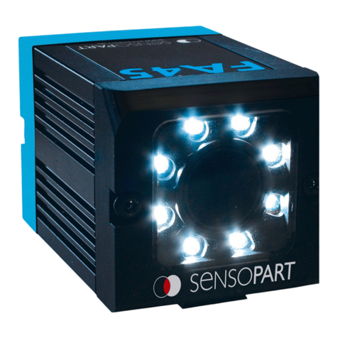
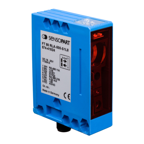
Sensopart FA 45 Series User manual

Sensopart

Sensopart FA 45 Series User manual

Sensopart FZS 1024 User manual

Sensopart

Sensopart FZS 1024 User manual

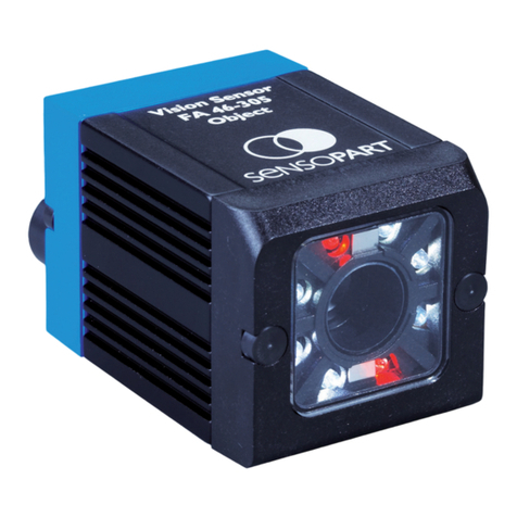
Sensopart FA 46 Series Service manual

Sensopart

Sensopart FA 46 Series Service manual

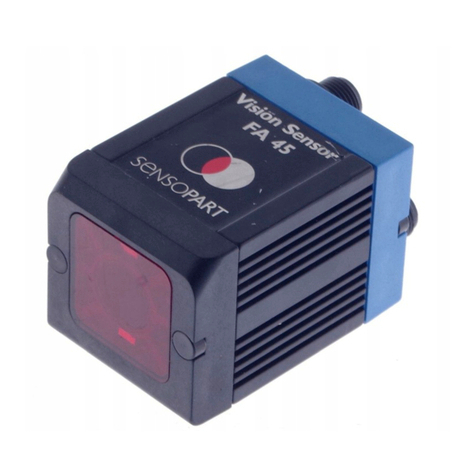
Sensopart FA 45 Service manual

Sensopart

Sensopart FA 45 Service manual

Sensopart FT 92 ILA - PSL5 Service manual

Sensopart

Sensopart FT 92 ILA - PSL5 Service manual

Sensopart FA 45 Service manual

Sensopart

Sensopart FA 45 Service manual

Sensopart FT 80 RLA Series Service manual

Sensopart

Sensopart FT 80 RLA Series Service manual

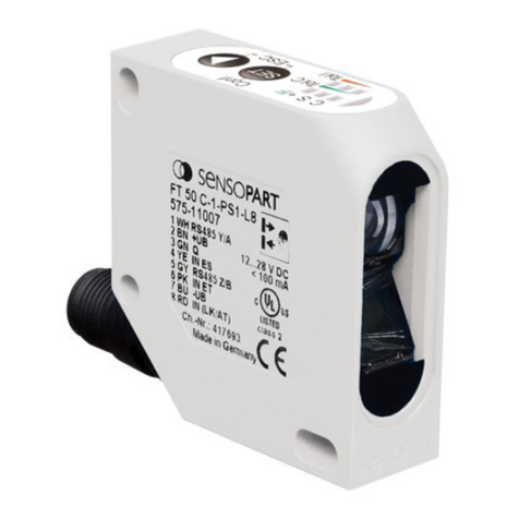
Sensopart FT 50 C S1 Series Service manual

Sensopart

Sensopart FT 50 C S1 Series Service manual

Sensopart FT 50 C S1 Series Service manual

Sensopart

Sensopart FT 50 C S1 Series Service manual

Sensopart FA 45 Series Service manual

Sensopart

Sensopart FA 45 Series Service manual

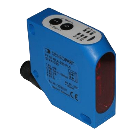
Sensopart FT 50 RLA Series Service manual

Sensopart

Sensopart FT 50 RLA Series Service manual

Sensopart FT 50 RLA Series Service manual

Sensopart

Sensopart FT 50 RLA Series Service manual

Sensopart SensoClip MBD F 25ST2 User manual

Sensopart

Sensopart SensoClip MBD F 25ST2 User manual

Sensopart FT 50 C-2-GIO-L5 Service manual

Sensopart

Sensopart FT 50 C-2-GIO-L5 Service manual

Sensopart FT 55-RLAP User manual

Sensopart

Sensopart FT 55-RLAP User manual

Sensopart FT 50 RLA 70-L8 Service manual

Sensopart

Sensopart FT 50 RLA 70-L8 Service manual

Sensopart FT 50 RLA-70 Service manual

Sensopart

Sensopart FT 50 RLA-70 Service manual

Sensopart Visor Use and care manual

Sensopart

Sensopart Visor Use and care manual

Sensopart FA 45 User manual

Sensopart

Sensopart FA 45 User manual

Sensopart FR 55-RLAP-70-2PNSI Series User manual

Sensopart

Sensopart FR 55-RLAP-70-2PNSI Series User manual

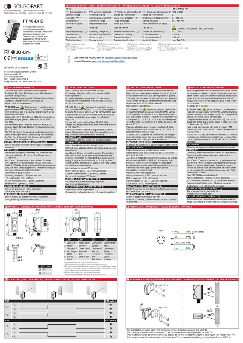
Sensopart FT 10-BHD User manual

Sensopart

Sensopart FT 10-BHD User manual

Popular Accessories manuals by other brands

Quincy lab 140AE-1 operating manual

Quincy lab

Quincy lab 140AE-1 operating manual

HomePro ZIR000 user manual

HomePro

HomePro ZIR000 user manual

DOL 20SCR Technical user guide

DOL

DOL 20SCR Technical user guide

RAB Smart Task installation manual

RAB

RAB Smart Task installation manual

Kemppi KMS 300 quick guide

Kemppi

Kemppi KMS 300 quick guide

Stearns 57,500 Series Installation and service instructions

Stearns

Stearns 57,500 Series Installation and service instructions

iGuzzini TWILIGHT COPENAGHEN manual

iGuzzini

iGuzzini TWILIGHT COPENAGHEN manual

Adelaide Annexe & Canvas Avan Deluxe installation guide

Adelaide Annexe & Canvas

Adelaide Annexe & Canvas Avan Deluxe installation guide

OHAUS 5000 instruction manual

OHAUS

OHAUS 5000 instruction manual

HOME8 WLS1300 quick start guide

HOME8

HOME8 WLS1300 quick start guide

MAXBOTIX MaxSonar quick start guide

MAXBOTIX

MAXBOTIX MaxSonar quick start guide

ioSmart iSmart56 Installation and user guide

ioSmart

ioSmart iSmart56 Installation and user guide

Focusrite Scarlett 18i8 user guide

Focusrite

Focusrite Scarlett 18i8 user guide

Velleman ED38105 user manual

Velleman

Velleman ED38105 user manual

JumpSport SkyBounce user manual

JumpSport

JumpSport SkyBounce user manual

Prima-Temp PRIYA Instructions for use

Prima-Temp

Prima-Temp PRIYA Instructions for use

Tefcold BC85I-BC85I W user manual

Tefcold

Tefcold BC85I-BC85I W user manual

Vaisala WMS302 user guide

Vaisala

Vaisala WMS302 user guide

manuals.online logo
manuals.online logoBrands
  • About & Mission
  • Contact us
  • Privacy Policy
  • Terms and Conditions

Copyright 2025 Manuals.Online. All Rights Reserved.