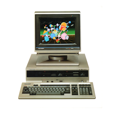
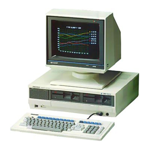
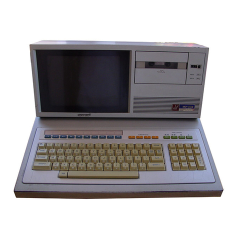
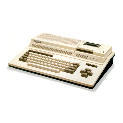
Sharp MZ-3500 User manual

\
""'
'I
J
'It
l
')
-.
•
MZ-3500
SHARP
SERVICE
MANUAL
CODE:
OOZMZ
3500SM/E
PERSONAL
COMPUTER
MODEL
MZ-3500
-------------CONTENTS
-------------..,
1. Specifications . . . . . . . . . . . . . . . . . . . . . • . . . . . . . • . • . . . • • • . . • . . . • • • • • • • • • • • . . .
..
1
2. Software (Memory) Configuration
..............•....................•..........
7
3.
CPU
and memory
...........................................•..•.•........
12
4. CRT
display.
. . . . . . . . . . . . . . . . . . . . . . . . . . . . . • . . . . . • . . • • • . . . . . . . . . . . . • . . . .
..
25
5.
MFD
interface
..................................•.....•.....•....•.......
52
6. R232C interface
......
. . . . . . . . . . . . . . . . . . . . . . . . . . . . . . . . • . . . . . . • . . . . . . . . . .
..
72
7. Printer interface
.......................................•.....•............
78
8. Other interface . . . . . . . . .
..
..,
. . . . . . . . . . . . . . . . . . . . . . . . . . . . . . . . . . . . . . • . .
..
81
9. Power circuit discnption . . . . . . . . . . . . . . . . . . . . . . . . . . . . . . . . . . . . . . . . . • . . . . . . . . .
..
87
10. Keyboard controller circuit discriptlOn . . . . . . . . . . . . . . . . . . . • . . . . . • . . . . • . • • . . • . . . .
..
90
11. Self check
functions.
. . . . . . . . . . . . . . . . . . . . . . . . . . . . . . . . . . . . . . . . . . . . . . . . . . . . .
..
94
12. IPL flow chart
...........................................................
103
13. Circuit diagram & P.W.S
Parts list & Guide
SHARP
CORPORATION
-
\173500
1.
SPECIFICATIONS
1-1_
Specification
of
the main unit (Model
35XX)
1) HIgh speed procesSing uSIng
multl-CPll
2)
Built
,n
minI
floppy
dIsk
Outl,ne
3)
Built
In pronter Interface and RS232C
<eroal
Interface
4) ConnectIon
of
up
to
two
vIdeo d,spla\
,""ts
(separate graphIC dIsplay
or
overlaId dISplay possIble on
two
,nd,v,dual
color
monItor
unots)
5) PermIts the
use
of
standard
CP/M
Model
3530
Incluse a single double-side, c'1uble density
minI
floppy
Model 3531 Includes a sIngle
double
sIde,
dIsk and
64
KB
RAM,
double densIty
minI
floppy
dIsk and 128
KB
Model
MZ3540
has
two
double-side,
densIty
mInI
floppy
dIsks and Model 3541
has
two
double
side, double
64
KB
RAM.
densIty
minI
floppy
dIsks, and 128 KB
CPU
Mu
Itl-CPU processing
Z80A
mIcroprocessor x 2
IPL
8K
Byte
ROM
ROM
C,G
8K
Byte
ROM
For
main CPU
64K
BIt
DRAM
x 16 chIps
or
8 chIps
MEMORY
For
sub-CPU
16K
Bit
SRAM
x 4 chIps
RAM
Shared
RAM
16K
BIt
SRAM
x 1 chIp
VIDEO
16K
B't
SRAM
x 1 chIp
RAM
4K
Bit
SRAM
x 2 chIps
LSI
Memory
mapper
TH
SP6102ROOl
Custom
LSI Screen
controller
CSP·l SP6102COO2
CSP
2 SP6102COO3
GDC
CRT
controller
jJPD7220
I/O
FDC
Floppy
disk
controller
jJPD765
PlO
Parallel
I/O
port
8255
SIO
Serial
I/O
port
8251
TIMER
Counter
8253
CLOCK
Clock
jJPDI990AC
Screen
structure
80
characters x
25
hnes,
80
x
20,40
x
25,
or
40
x
20
Elements
8 x
16,8
x 8
DISPLAY
Attribute
Reverse,
blink,
hne (hOrizontal, vertIcal)
Colors
8 colors
on
each character and
background
color
IIF
2 channels (applicable
CRT
640
x
400,
640
x
200,
B/W
or
color)
One
double-side,
MZ353X
double
density
256
bytes/sector, 16 sectors/track,
80
tracks/disk
MFD
floppy
disk
Two
double-side,
MZ354X
double
density
Built-in
interface
for
optional
MFD
floppy
disks
LIght
pen
( )
Other
I/F
Keyboard
Dedicated
keyboard
--
---------~
-
-----
Pronter CentronlCS
,"terface
RS232C
No
protocol,
asynchronus mode,
110
to
9600
bps,
half-duplex
Other
Speaker
(500mW)
Battery
backup
clock
I
HALT
SW Speaker volume
control
functions
HIgh class
compatIble
wIth
PC3200
BASIC,
supplemented and graphIC
BASIC
control
commands
Expanded RS232C, GPIB, and GPIO
FDOS
Software
Utilities
BACKUP,INIT,
COPY,
DEBUG,
KILLALL
CP/M Basic
CP/M
Expanded
CP/M
I
ntstruct,on
Manual
Accessoroes master
floppy
disk
power
cord
-)-

-
MZ3500
'-2.
MZ-1KOl (Keyboard)
specification
MZ1K02 U.S.
keyboard
(ASCII)
MZ
1K03: U.K.
keyboard
(ISO).
Outline MZ1K04 German
keyboard
MZ1K05:
French
keyboard
Keyboard
controller
8OC49
or
8749
LSI,IC
CMOS1C
4049
x
2,4514
Sculpture
key
Mechanical
contact
key,
with
life
of
10,000,000
operations.
Keys (98)
Alphanumeric
keys 61
Ten
key 1
15
J
Function
keys J 6 J Definable keys I
10
Mode
switch
1
Interfacing cables
For
data
transfer
with
the
CPU (serial)
and
power
supply
!transmission
under
15,000
baud)
Specification Use
of
coiled
cable
with
8-pin DIN plug
Repeat
function
Automatic
repeat
occurs
0.64
seconds
after
1
2 1
Two-key rollover
Other
continuous
depression
of
the
same
key_
Indicators
(4 LED's) POWER, Alphanumeric keys
Molded
I
Color
Office gray
Cabinet
Size
(W
x H x
LI
467
x
35
x
190
1 Weight 1
About
1_5kg (3_3 Ib)
Keyboard
layout
Refer
to
the
page
7IN
"CIRCUIT
DIAGRAM"
1-3. MZ-1U02
Expansion
unit
for
the
MZ-3500
series CPU, which
can
be
attached
to
the
rear side
of
the
main unit_ /
Outline
Optional
boards
are plugged in
to
the
expansion
box.
The
expansion
box
will
accomodate
up
to
four
option
boards.
Number
of
slots: 4 slots
Slot
connector.
60-pin
edge
connector
x 4
Specifications Area
of
the
slot
inserting
option
board:
140_5 x
140
Slot
for
option
and
slot
number
Slot
1
Slot
2
Slot
3
Slot
4
MZ-1R06
0 0
(expansion
RAM)
SFD
IIF 0 0
Expansion
RS232C 0 0 0 0
GPIO 0 0 0 0
GPIB 0 0 0 0
(I
EEE I/F)
-2-

-
MZ3~O
Expansion
unit
-----
-
-----
--~
Screw (2)
Screw (1)
\ \ ,
Screw (2)
,
\~
Screw (1)
1-4. MZ-IR03
Optional
board used graphic display
functions
with
the
Model-3500
series CPU.
It
includes
32KB
of
RAM.
Outline
It
is
inserted
through
the
slot
on
the
front
panel
of
the
PU.
The
MZ-1U02
expansion
box
is
not
required.
GDC
1
Graphic
controller
"PD7220
LSI Basic
(buit-in)
16KDRAM
x
16
(32KB)
VIDEO
RAM
Expansion
16KDRAM
x
32
(64KB)
(optional)
Specifications
~M
32KB
96KB
(basic)
(maximum
e)(pansion)
Graphic
functions
640
x
200
640
x
200
dots
640
x
200
dots
(Col
or
must be green
monitor
Two
screens
Six
screens
specified
for
each
640
x
200
-------
640
x
200
dots
dot.
when the
color color
monitor
Two
screens
video
unit
is
in use)
640
x
400
640
x
400
dots
640
x
400
dots
green
monitor
One
screen
Three
screens
(
640
x
400
-----
640
x
400
dots
color
monitor
One screen
SDISP Screen designation
for
two
video
units.
BASIC
graphic
control
statements
ODISP
Designation
of
output
screen.
Software
CHANGE
DISP
Mode
designation
GCOLOR
Graphic
pattern
designation
CLS
Cleared
by
the
color
specified.
PSET
Dot
set
PRESET
Dot
reset
LINE
Line
creation
GTABLE
Table
creation
CIRCLE
Circle
creation
PAINT
Paint
over
GINPUT
Input
of
graphic
pattern
GDISP Display
of
graphic
pattern
GPRINT
Output
of
graphic
pattern
on
printer
GREAD
Read
of
coordinates
GENTER
Input
of
pattern
within
the
specified
area
GCURSOR
Graphic
cursor
position
designation
GSCROL
Graphic
screen
scrolling
SYMBOL
Graphic
symbol
displaying
SCALE
Scren scle-down designation
-3-

-
MZ3500
[J
I I I I I I I I
11
~
1-6. MZ-1R06
Optional
board
for
memory
e)(pantion
of
the
MZ-3500
sries CPU.
with
thIS
option
the
main
memory
(RAM)
can
be
e)(panded
Outline
up
to
a
ma)(imum
of
256
KB.
This
option
plug
into
the
e)(pantion bo)(
in
slot 1
or
3.
Basic I
64KDRAM
x 8
(64KBI
LSI I
64KDRAM
x 8
(128KB)
Specifications
E)(pansion
Memory
and user
Main
CPU
only
Use
of
MZ-1R06
Using
eight
64K
RAM's
area
on
the
MZ-1R06
Total
capacity
of
128
KB
192
KB
256
KB
the
main
CPU
RAM
SYSTEM
•
57
KB
--
BASIC
AREA
(RAM
USER
BASE)
AREA
80
KB
128
KB
208
KB
, \ ,
" , \ \
" "
"
\,
,.('\
,
',~.~Y
'~~~
~~~?
-4-

(
1-7_
MZ-1007
Outline
High resolution
MZ
3500
series
12
green
monItor
Video
tube
Display capacity
Specifications
--
DISplay
sIZe
I
nput
Signals
Power
supply
Cabmet
AdJusting
knobs
Accessories
~
Type
Non
glarp green ISize
Fluorescent
cOl
or
P39
(green, long
PERSISTANCE)
Total
number
01 I
2,000
characters
1~
Display
capacity
dISplay
characters
(80
characters
x
25
Imes)
-
220
x
145
Method
Separate
mput,
TTL
level
-HOrizontal
2086kHz
!
Vertical
"}<;JW
power
consumption
Molded
Color
IOffice gray
Size
{W
x H x Ll
!324x310x356
! Weight
3 Vertical
synchronization,
contrast,
brightness
CPU
connection
cable
and
power
cord
and
Tilt
stand
-!)-
N
N
N
..
MZ3500
I
12",
90
0
deflection
1
640
hOrizontal
dots,
400
vertlcallmes
I
478Hz
! 7_2 kg
--

-
MZ
3500
1-8. System configuration
of
Model
3500
12"
green
monitor
MZ·1007
12"
color
'---
monitor
MZ-1008
Keyboard
MZ·1K02
MZ·1K03
MZ·1K04
G-RAM
G-RAM
MZ·1K05
MZ-1R04
MZ-1R04
LIght
pen
I
MZ·1X02
Pronter
r-
MZ·1P02
GRAM
Board
MZ-1R03
Cable
;--
MZ-1C16
t---
~
Color
,nkjet
'---
printer
MZ·1P04
r-
,--
-
--,
I
p.
r---I ronter I
..-
I CE-332P I
r--l
Cable 1
_____
J
~
r-
MZ-1C03
r--
,-
--
-
-,
1
Printer
I
1
102824E
I
I
_____
J
Model-3531·
Cable
Option
MFO
MZ-1C07
MZ-1F02
~
Option
MFO
,..-----,
MZ-1F03
Cable I
OptIon
MFOI
'---
MZ-1COO
CE·331M
I
I
L
____
...J
RS-232C RS232C
I/F
r-
-Cable
MZ-1EOl
MZ-1C05
I--
GP
I/O
Cable
MZ-1E02
MZ-1C19
Expansion
f}
'--
unit
MZ-1U02
r-
SFO
IF
OptIon
SFO
Option
SFO
MZ-1E03
MZ-1F05
MZ·1F05
Option
RAM
'---
PWB
Option
RAM
·Model·3541
~
Model·3531
+
MZ·1F03
MZ-1ROO
MZ·1R07
-6-
,
I
l~

-(
..
MZ
3500
2.
SOFTWARE (MEMORY) CONFIGURATION
Memory will be
operated
under
four
states
of
SOO
~
S03,
depending on
the
hardware
and
software configurations.
In
the
paragraphs
to
follow, description will be
made
for
those
four
states.
MA3
MA2
MAl
MAO
MAIN
CPU
o
o
o
o
o
o
o
~
FFFF
FFFF
1
jRAM<COM)
~.
t,
COOO
BFFF
8000
7FFF
RAMA
4
RAMA
3
----
RAMA
2
4000
3FFF
I
I
) :
ROMB
I I
2000
L
____
J
RAMA
1
-
--
OFFF
EJ-
ROM
~
IPL
_
--
0000
---
"
\\
,\
\'
,\
"
---
--
\
,\
'\
2-1.
SOO
(INITIALIZE
STATE)
SOO
can
only
exist immediately
after
power
on,
and
the
system executes IPL under this
condition
and
that
the
system thus loaded will automatically assign
memory
area
for
SOl,
S02,
and
S03.
SUB
CPU
MSl=O(L)
MSO=O(L)
--
--,
\,
\\
\\
\\
\ \
\\
\\
\\
\ \
\ \
\,
\ \
\ \
\ \
\ \
\ \
\ \
\ \
\ \
\
L
____
,
I I
I ROM I
'(SPAPE)
I I
I
RAM
so
RAM
SC
RAM
SB
RAM
SA
5F
,
FF
5800
57PF
5000
4FFF
HM
4000
\
27
FF
RAI,I(CQM)
20
1
00
1
FFF
---
ROM
IPL
---
--
--
L-
__
....J
0000
-7-

-
MZ3500
Operattonal
description
(1)
Upon
reset
after
power
on,
the
main CPU loads
the
contents
of
the
initial
program
loader
(IPL)
into
RAM
starting
at
address
4000H,
during
which
time
reset
is
applied
to
the
sub·CPU.
TIMING OF RESET SIGNAL
Vee
SYSRES·l.j
.,
I
1-
I I
.....
-----/
SRES
I I I
I I +
~
I I I
I
I
of
POWER'SUB CPU
I START POWER
OFF
I
I
MAIN
CPU
START
Memory
Map
Data:
1.
ROM·B
is
tested
to
determine
if ROM's
are
present.
2.
The
ROM·IPL
functions
under
control
of
the
main
CPU
at
first,
but
later
it
functions
under
the
sub-CPU
after
the
IPL
program
has
been
loaded
in RAM.
3.
RAM·COM
is
shared
by
both
the
main
CPU
and
the
sub-
CPU.
INITIALIZE
FLOW
START
Lwd
...
800TSTRAP
""'-
~"A~ll
~TART
ll'
\4
....
JAf< I
T....wf.r
control
to
the BOOTSTRAP
Tf1II'\'Ifef'SUB-CPU
sv.-..rr
Pf"ograt'n
to
lh~
sus-CPU
}-
'11.)
........ ,
,I<"
-8-
(2)
The
main
CPU
then
terminates
resetting
the
sub
CPU
and
starts
the
sub·CPU.
At
the
same
time,
the
ROM
IPL
is
assigned
to
the
sub·CPU.
(3)
The
main
CPU
then
send
the
memory
allocation
(state)
to
SD1,
and
starts
to
load DOS
from
the
system
floppy
disk.
Signal
generated
from
the
CR
network
and
power
supply
Output
Signal
from
the
main
CPu
port
8.
Main
CPU
reset
time
b.
Main
CPU
IPL
load
tIme
4. Memories
other
than
described
above
cannot
be
accessed
under
the
SDO
state.
5. Bank
select,
MAD-MA3,
is
used
Within
the
address
range
of
COOOH-FFFFH.
EAROR
"iliA!
III
"NlI
....
1-/1(
,........ ,
\k
J

(
(
ROM-IPL
1.
An
8KB
ROM
(2764
or
mask
ROM
equivalent)
IS
used
for
the
ROM-IPL
2_
When
the
system
reset signal
turns
from
low
to
high
state
after
power
on,
the
main CPU
starts
to
operate
At
this stage,
the
ROM-IPl
is
addressed_
3_
The
CPU
starts
from
address
OOOO(ROM
address
10000)
4_
The
main CPU sets
the
sub-CPU reset signal
from
low
to
high
state
as
It
goes
out
of
its initial
state
via
the
memory
mapper
and
the
sub-CPU
starts
to
operate_
At
this pOint,
the
ROM-IPl
is
addressed
by
the
sub-CPU_
5_
Address
0000
of
the
sub-CPU
is
ROM
address
(0000)
The
memory
area
above
ROM address
(1000)
cannot
be
used by
the
sub-CPU because
the
main CPU initial
program
has
been
loaded
there_
2-2.
SOl
(SYSTEM LOADING & CP/M)
SOl
determines
which
operating
system
IS
in
use_
The
system
is
loaded
in
the
CP/M (Control
Program
for
Micro-
processors) mode_
NAIf>,
(I'll
FFFF
,-----,.
I
RJ\M'(l(»-I
fH~I---'-~
, \
, \
\\
"
\ \
,\
,\
"
"
"
-
MZ
3500
Main CPU logical
address
(during
IPL
operation)
ILogical
address
of
the
sub-CPU
O~H
0800
--
OHF
0000
N~I~O(
L)
10150= I
(HJ
\'
\\
\
,,
,,
\ \
,,
-9-
,,
,\
,\
,\
\ \
\ \
\ \
\ ,
\ \
\ \
\ \
"
\
SUB
CPU
--
--,
RAM
so
RAM
se
RAM
'8
RAM
"
J<.A\f<
(OM)
kOM
Il'l
1
IFH
1800
171'1'
1000
01'1'1'
0800
071'1'
0000
5FFF
5800
S7Ff
m~
-4800
41
FF
..
000
27H·
2000
'T
(,000
ROM
physical
address
~
1FFF
4
~
171'1'
ROM 1PL
1000
8KB
OFFF
0800
071'1'
0000
!

------~------~----
-
MZ3500
Operational description
(1)
As
soon
as
the
sub-CPU
is
started,
it initializes
the
I/O
port
and
waits for program
transfer
(IOCS)
from
the
main CPU. This IOCS
(Input
Output
Control
System)
is
the
program resident
at
address
4000H-5FFFH.
(2)
As
the
main CPU loads
the
information
from
sector
Communication
between
Main and SUB CPU
READY
MAIN
BUSRQ
SUB
CPU
BUSACK
CPU
l I j
~
COM
RAM
2.3.
S02
(ROM
based
BASIC)
SD2
is
active when
"SHARP
BASIC"
is
executed
via ROM.
MAIN
CPU
["~
RAM
BANK
MA2
SELECT
MAl
IIAO
FFFF
COOO
BFFF
0 0
0 0
0 0
0
1<-\.\lA
3
2
0 0 0 0
0 0 I I
0 0
0 0
1.:1
~
0
I
0
I I I
4000
3FFF
\
1<0101
2000
IFFF
IROMcl
IRON~
IROMII
II<
OM21
11<010131
IROM41
~
RONA
0000
{
1102
MOl
MOO
o o
o o
o o
''1''
of track
"0"
of
the
floppy
disk, it loads
the
IOCS
and
bootstrap
routine
to
the
sub-CPU.
(3) The
bootstrap
program IS loaded
next.
(4) The
bootstrap
program
determines
memory
allocation.
BUSRQ
L
Output
COM
RAM
Se
t
..
BUSRQ
H
OUTPUT
•
(ISOLATION
OF
COM
RAM)
M~I
= I
(H)
M~O
= 0
L)
I I I
3
~\
\ \
\\
\\
SUB
CPU
,----,
I
\\
\\
\ \
\\
\\
\\
\\
\\
\,
~~
~g
\'
RAM
SB
\\
RAM
SA
\
\'
1. Bank select,
MAO-MA3,
is
effective
for
memory
area
COOOH-F
FFFH.
2.
Bank select,
MOO-MA2,
is
effective for
memory
area 2000H-3F FFH
-
10-

2-4. SD3
(RAM
based
BASIC)
SD3
is
active when
"SHARP
BASIC"
IS
ececuted
via
RAM.
"SHARP
BASIC"
is
loaded in
RAM
from the
floppy
disk.
MAIN
CPU
MA3
0 0 0 0
RAM
MA2
0 0 0 0 I I
BANK
MAl
0
SELECT
0 I 0 0
MAO
0 0
MSI=HHI
MSO=}(H)
I
0 0 0
0 0
FFH
I:I~
~~
~\
r"
I
a
IFFF
0000
ROM
~N02
0
BANK
10101
0
SELECT
10100
0
RAMB
0 0
0 I
0
IROMlllROMzl
IkO~31
I
kOM4
1
o I
o
o
I
o I
o
1. Bank select,
MAO-MA3,
is
effective for
memory
area
COOOH-FFFFH.
2. Bank select, MOO-M02, is effective
for
memory
area
2000H-3F
FFH.
Operational description
The
state
of
the
system
is
determined by
the
bootstrap
program before
the
load
of
the
system program.
-11
-
---------.
---
-
\\
"
\\
"
..
MZ
3500
SUB
CPU
'\
'\
\ \
,\
\ \
\ \
\, I
\:'
1mB
\\
RAN
se
\~\
M ROMS
\\8
(00Id
RON
IP
ROM BASE
OFTHE
SUB CPU

;::;
3.
CPU
AND
MEMORY
3-1. Block diagram
1)
Relation between MMR (Main Memory Mapper) and
main memory.
3211Hz
Ea
CLOLK
(,16MB!
4Nfb
SEll'
CUSTOM
LS'
NFNORY
M~PPER
r-------,
~
RA'"
~~
!:,...--_"'_.T_'O_"_....,
:
~"AN
I
•
'28KB
'64KB'Z)
I
L:
______
-J
:-
;O;O;T~"-
- - i
Lf--
ROM(
BASIC)
I
32KB
I
or 8KBM4 I VFO
...
_--
~--...I
'41\[
....
II
tJ
7 -
80A
IOWI
~
"ul
h'll
f--
BU~
AlII
f--
'>NIVH
U
f--
TRL
L...---
....
llR
LrU
A~
,
RaA
'"
LTRI"
f--o
-'2'
~.<;v
~.llV
I r
I
1 T
I r
I I
(
I>L
722n
~
~'PLFXFR
I
[
BUFFER]
r-f-~
--,
'I
11
Wl
"
1I1b:_",7
..
2
..
2~0i""".!l
"
...-------'L_---.Jf
\I
nt-
()
RAM
I
lIlARAllFR
t,
F 1
JKB
2K
X
1'
RO),4
8KH
:
'.RAP",c$rXR
I
111'1
ION
,~
)-
(rltO
,
"""I
V,
flH1
"AM
I
m
'i2KH
I
,.....1
I,d'
"""
(]"AN
I
ITl
32K~
'-------'
I
r-+-+-I;-,'!..i"
V,,)
H)
"AN I
101111111
I
r.U)
I(
2{lO
"--
__
-'
~1
, L
______
J
I
'I
3,KH
OW
1111
11
F..l0)(
400
"'''''~
12
r
14
Lol
r
12'
(,rN'fl
11
."
\41
ur.,rOM
11
11
I'"
I
l'il
- 2
JI
)-
L-...jl
~EN'
CU~TOM
11
"'------/
I<l:'.
--J(2C
2L!..1='
="
'=C='="
-='
==ljJl
tZ'
or
14~
Lulnr
(
I
SlO
R2 51
11
F'le
765
~
RAM
nr
ROM ]
8KB
~
I
r
11
11
¥1
WllNm
~
8258
i J
I
nklVI-R
Ir
l!\!I-1'<llfoR
I
Rfolfol\"'~
U
(J(K
IqgOl
RS-232L
IIf
)
11
DRIVER
I
RECEIVFR
r
IJNP(lT PORT I
If
L<;2~~
1
I
I MFIl I
,-
- - - - - - -
-I
41
~FD
I:
,
OPT'ON
I
l.
________
J
j------------
'"I
I I
I
~LOT'
I
I
I I
I
""flT2
I
I
I
I
r-1
"'L{lT3 I
I
I I
, '-----1 1 I
....
[nT4
, I
,
'qOT
I
L~)~I~N
__
!!Z~01
_
__
- -
.J
1
I I
pro
82'5
11
I
I -----,
I
=
1\,..'
h
l(I'\jTR()J
1
~
k 0
~=====<="=',)'=====r==~~
,
,
,
I
AMI r
111-/
r \,.. R I i 1
I
,,,]
;,
~
( PRINTER , ,
")
D"I
H 1,\).11
,
Ml11(02
I
111;0J
:~~
I
__
J
il
o

3-2_
Main CPU and
I/O
port
A2
AS
M
A4
A
A5
N
A6
A7
C
p
IORQ
U
MT
1
ADDRESS
A7 A6 A5 A4
A3
A2
Al
AO
0 0 0 0 0 0 0 0
0 0 0 0 0 0 0 1
-
1 1 0 1 1 1 1 0
1 1 0 1 1 1 1 1
1 1 1 0 0 0 X X
1 1 1 0 0 1 X X
1 1 1 0 1 0 X X
1 1 1 0 1 1 X X
1 1 1 1 0 0 X X
1 1 1 1 0 1 X X
1 1 1 1 1 0 X X
1 1 1 1 1 1 X X
HEX
00
01
-
DE
OF
EO
-
E3
E4
-
E7
E8
-
EB
EC
-
EF
FO
-
F3
F4
-
F7
F8
-
FB
FC
-
F F
A
YO
B
YI
C
Y2
G2A
Y3
Y4
G2B
Y5
GI
YG
Y7
Connector
I
Fe2
r:;----,
~-----;.-n
O--.;...1i::"))
~FDC
INTA
D---:--':C)
MF
DC
L_~~...J
-
MZ
3500
This paragraph discusses main
CPU
I/O
port
select and addressing_
The address
output
from
the
main
CPU
is
decoded in
the
74LS138
to
create
the
select signal.
Table below describes address
map
and
signal functions.
IOAB(MEMORY
MAPPER)
74LSI38
Signal name
Description
~
/
NOT USE
/
~
-----
~
NOT USE
~
~
SFD
.nterface
FDC
chip
select.
SFOC
(UPD765)
AD
used for AD
and
WA.
A1
IS
"don';
care".
---
>----_.
10SF
SFD
onterface I/O
port
and
DMAC
chip
select.
Interrupt
signal
from
the
sub-CPU
to
the
main
CPU.
INTA
Flipflop
resetting
signal.
~
~
NOT USE
~
~
MFDC \UPD765)
MFD
Interface
FDC
chip
select.
MFD Interface I/O
port.
lOMF
AD
used for AD
and
WR.
A1
IS
"don't
care".
lOAB (MEMORY MAPPER)
I/O
port
select
on
the
memory
mapper.
AD
and
A1 used
during
RD, WR.
-
17-

-
MZ3f:i)O
3-3. Sub-CPU and
I/O
port
AS6 3
AS5 7
SUB
AS4 1
CPU
AS7 4
...
5
...
MT
6
lower 0
N §
M
....
0
~
8 00 8 0
(1)
8 0 0
~
0
upper
~
~
AS
7654
MEX 0 1 2 3 4 5
0000
0
_SOO
0001 1 -501
8251
0010
2
S02
8253
0011 3
503
8255
7
Y7
C 9
Y6
B
10
Y5
A
11
4G
Y4
G2A
Y3
12
I~
G2B
Y2
14
Gl
YI
15
YO
74LSI38
0
....
0
~
8
....
~
~
~
~
0 0
0 0
~
....
6 7 8 9 A B
507
--"'
506
505
504
503
502
SOT
500
8 0
0
~
~ ~
~
~
~ ~
C 0 E
GI>C-I
Graphic
option
Shown
at
the
left
IS
the
circuit used
by
the
CPU
to
select
the
I/O
ports
The
out
put
address from
the
sub
CPU
IS
decoded
by
the
74LS
138
to
create
the
sel
eet signal.
Shown
below
is
the
address
map
and
select signals.
CSP-I.CSP-2
Input
port
select (LS244)
8255-CS
8253-CS
8251-CS
MAIN CPU·INT
....
~
~
Signal description
~
F
~
Output
signal
to
set
the
flipflop
to
apply
interrupt
(INTO)
to
the
main CPU. Enables
communication
between
CPU·s.
8251
510
chip
select.
:!Io
ASO
is
used
for
data
control
selection.
AS1,
AS2,
and
A53
are
"don't
care".
8253
counter
chip
select.
A50
and
ASl
are used for programming
during
write.
AS2
and
A53
are
"don't
care".
8255
PlO
chip
select.
ASO
and
AS1 are used
for
port/control
selection.
AS2
and
A53
are
"don't
care".
8·bit
input
port.
0100
4
504
input
port
select
Used
for
read.
AS3 are
"don't
care".
CAT
control
110
port
chip select.
0101 5
505
AS1,
AS2,
and
AS3 are used for write.
ASO
is
"don't
care".
UP07220
(graphic)
chip
select.
0110
6
506
ASO
is used
for
read
and
write.
ASl,
AS2,
and
AS3 are
"don't
care".
UP07220
(character)
chip
select.
0111 7
507
ASO
is used for read
and
write.
AS1, AS2,
and
AS3 are
"don't
care".
1000
8
~
/
1001 9
1010
A
1011 B
1100
C NOT USE
1101 0 /
~
1110
E
1111 F
-
18-

3-4.
Memory
mapper
(MMR)
SP6102R-OOl
1)
Block
diagram
ADDRESS BUS
A 0 . I
.13
.w.
r
AI4
AI3
AI
AO
COAB
MREQB
RFSH
00-7
h-
r---v'
Memory
mapping logic
"15
AI4
A
13
R()~1
11'1
COAI:l
RAM
COM
MRI:QB
RF::'H
~
ME2
-
OUT
MEI
*FF
{~
~Q
Q
"'"-
BANK
SELECT
1/0
CONTROL
BUS
M£RQ
RFSH
Rn
WR
DATA
BUS
00-07
C)
PORT
LOGIC
-
-
7"
r
"-
-
'---
WAil
TIMING
GENERATOR
CLK
TO
RESET
~
SIGNAL
MA3
l MA2
MAl
O~
OUT
MAO
*FE
M02
MOl
MOO
'----'
~
4
SR£S
Jo..
OUT
MSI
O~
*FO
MSO
STATE
"'"---
SWITCHING
-
SRQl.
-;
OUT
*FC
El
¥-
r--
O~
IN
~
*FE
~
~
~
FROM
011'
~
SW
"'"---
-
F03
F02
~
FDI
~-
JI.
IN
SROY
00-7
L..
SACK
¥
*FF
.....
INP2
~
INPI
.....
INPO
-
INTB
-
19-
ST
SRES
SUB CPU
RESET
SUB CPU
SRQB
BUS
REOUEST
SUB CPU
SRDY
READY
~
SUB CPU
ACKNOWLEDGE
1
El
INTERRUPT
PRIORITY
ENCORDER
-
MZ3~O
.....
.....
.....
...
......
......
RmflPL
RAM
COM
SROY
Il'\TI
lNT2
1,'T3
I!'.T4
I!'.TFll

..
MZ3500
2)
Memory
mapper
(MMR)
SP6102R·001 signal description
Polarity
Pin NO.! IN/OUT
Function
Signal Name
1
ST
IN
Main CPU DRAM
output
buffer
(LS244) switching strap. .
2
DO
Bidirectional main CPU
data
bus.
--IN/OUT (Data bus 0 -
7)
9 D7
-----
---
10
A15
Main CPU address bus.
--
IN
Used in
the
memory
mapping logic
of
the
MMR
for address
output
for the DRAM, ROM,
and
12
A13
shared RAM. (Address
bus
13
-15)
Main CPU address bus,
13
A1
IN
Used in
the
I/O
port
select logic
of
the
MMR
to
assign device
number.
Sub-CPU bus request signal.
•
After
power
on:
Halts
the
sub-CPU.
14
SRES OUT •
After
write
command
(LDA·BOH:
OUT#FD)
by
the
main
CPU'
Starts
the
sub-CPU.
This signal
is
issued
after
transfer
of
the
main CPU program
contained
m
the
ROM·IPL.
(Sub CPU Reset)
Sub-CPU bus request signal.
•
After
power
on:
Resets
bus
request
to
sub-CPU.
--
•
After
write
command
(LDA·02H:
OUT#FC)
by
the
main CPU: Place bus request
to
the
sub-CPU
15
SRC
OUT This signal
is
issued
to
bus
of
the
sub-CPU,
after
the
main CPU writes
to
the
shared RAM a
command
parameter
to
the
sub-CPU
or
reads
the
message
status
from
the
tub-CPU,
(Sub CPU Request)
16
AR13
Address signal
to
the
main
CPU
dynamic
RAM.
--OUT
The
main CPU addresssignal$.,A13·A
15,
merged in
the
memory
mappmg
logiC
CirCUit
to
produce
18
AR15
AR13-AR15.
This
is
means by which
the
4 basic
and
CP/M
memory
maps are made, along With
MS
1
and
MSO,
BASIC
interpreter
32KB mask ROM
chip
select signal.
19
R32
OUT Valid when
SD2
is
active (Sharp ROM based BASIC).
Command
(LOA 02H OUT
3F
D)
(ROM 32K select)
Internal
MMR
I/O
port
select logic signal.
20
10AB
IN
Goes low
by
the
command
IN/OUT
#
FC-#
FF.
(Input/Output
Address)
------
21
SRDY
IN
Input
of
ready signal
from
the
sub-CPU.
(Sub
CPU
Ready)
Chip
select signal issued
from
the
main CPU
to
the
SKB mask ROM.
--
22
ROPB
OUT
Valid with SDO active (initialize
state).
(ROM ipl)
--
23
ROAB
Chip
select signal
for
four
chip
BASIC
interpreter
SKB EPROM (A,
B,
C, Dl.
--
OUT
Valid with
SD2
active (Sharp ROM based BASIC!.
26
RODB
"R32B
(alternate
choice
with
the
32KB mask ROM
chip
select signal).
(ROM
A-D
Buffer)
27
RSAB
Row
address select signal
for
the
main CPU
dynamic
RAM (block A·block D).
--OUT RAS (ROW ADDRESS
SELECT;
LINE ADDRESS SELECT)
SIGNAL
30
RSDB
(Row
address Select)
Input
of
bus acknowledge signal from
the
sub-CPU.
31
SACK
IN
( When
the
malO CPU
must
write a
command
in
the
shared RAM a bus request IS Issued flfst,
then
the
)
command
is
written
in
the
shared RAM
after
acknowledgement from
the
sub·CPU
At
the
end
of
the
command
cycle bus request IS released and the sub CPU
executes
the
command
-
20-

Polaflty
Pin
No.
IN/OUT
Signal
Name
32
RF1B
OUT
33
RF2B
OUT
34
WATB
OUT
35
RCMB
OUT
36
ITFB
IN
37
!TOB
IN
38
InB
--
IN
39
IT2B
40
MRQB
IN
41
WRB
IN
42
IT3B
--
IN
43
IT4B
44
SEC
IN
45
GNO
IN
46
Vcc
IN
47
SW1
--
IN
48 SW2
49
AO
IN
50
RFSH
IN
51 SW3
--
IN
52
SW4
53
GNO
IN
54
F01
IN
55
Vcc
IN
56
F02
IN
Function
MalO CPU
128KB
dynamic
RAM
output
buffer
(LS244)
output
enable
signal.
(RAM
buffer
1)
Signal
Identical
to
R F1B
For
option
RAM
(RAM
buffer
2)
Wait Signal
to
the
main
CPU
-
MZ
3S00
(One
wait
cycle
's
applied
dUring
the
memory
fetch
cycle
of
the
main
CPU.
It
consists
of
one
clock
period)
(WAIT)
Chip
select Signal Issued
from
the
malO CPU
to
select
the
RAM
shared
by
the
main
CPU
and
the sub-CPU
(RAM
Common'
Interrupt
input
from
the
UP0765
FOC
(Floppy
Disk
Controller).
(Interrupt
from
Floppy'
Interrupt
Input
from
the
sub-CPU.
11
nterrupt
from
No.
0)
Interrupt
Input
from
slot
1
or
2.
(I
nterrupt
from
No.
1,
2'
Memory
request signal
from
the
main
CPU.
(Memory
Request)
Write
Signal
from
the
maon
CPU.
(Write)
Interrupt
Input
from
slot
3
or
4.
(I
nterrupt
from
No.
3,
4)
Input
from
the
FOO
(Floppy
Disk
Drive)
assignment
dip
switch
(A),
'110.1.
·See
the
dip
sw,tch
deSCription,
provided
separately.
(Section)
Ground
5V
supply
Input
from
the
s,stem
aSSignment
dip
sWitch.
'See
the
dip
sWitch deSCription,
provided
separately.
MalO
CPU
address
bus
Used
10
the
I/O
port
select
logic
in
the
MMR
to
designate
device
number.
Refresh signal
from
the
main
CPU.
(Refresh)
I
nput
from
the
system
assignment
dip
switch.
·See
the
dip
sWitch
description,
provided
separately.
Ground
Input
from
the
system
aSSIgnment
dip
switch.
'See
the
dip
swotch deSCription,
provided
separately.
5V
supply.
Input
from
the
FOO
aSSignment
dip
sWitch
(A),
No.
2.
'See
the
dip
sw'·ch
deSCription,
provided
separately.
-
21
-
I

-
MZ 3500
PIn
No
Polarity
Signal Name
57 SYSR
58
FD3
---
59 COAB
60
R01B
61
GND
62
Vcc
63
R02B
64
R038
65
ROB
66
CLK
67
R04B
68
MPX
69
GND
70
CASB
71
GND
72
INT8
73
INIOUT
IN
IN
IN
OUT
IN
IN
OUT
IN
OUT
OUT
IN
OUT
IN
OUT
Functton
----
---
------------
System reset signal.
Used
to
reset 1/0
port
in
the
MMR.
(System Reset)
-
--
----
-----
--
-------
--
Input
from
the
sytem
assignment
dip
switch.
·See
the
dip
switch
description,
provided
separately.
----
---- -
~-------
---
--
----
Shared
RAM
select signal.
Address
of
the
shared
RAM
is
#F800·#FFFF
for
the
main
CPU
(Common
RAM
Address) -
--
Select signal
for
8KB
area allocated
to
slot
1.
Valid
when
SD2
is
active
(ROM
based BASIC) and SD3
(RAM
based
BASIC)
(ROM
1)
Ground
5V
supply
Select signal
for
8KB
area allocated
to
slot
2
or
3.
Valid
when
SD2
is
active
(ROM
based BASIC) and SD3
(RAM
based
BASIC!.
(ROM2,3)
Read signal
from
the
main CPU. (Read)
EAIT
signal generation
clock.
(Clae")
Select signal
for
8KB
area allocated
to
slot
4.
Valid
when
SD2
or
SD3
(RAM
based BASIC) are active.
(ROM
4)
RAS/CAS
address
switching
signal
for
the
main
CPU
DRAM.
High:
Row
address
Low:
Column
address
(Multiplex)
Ground
CAS
(Column
Address) signal
for
the
main
CPU
64K
DRAM.
"Refresh
for
the
RAM
only.
(Column
Address Select Bu ffer)
--------------------
--
Ground
Interrupt
signal
to
the
main CPU.
(I
nterrupt)
Not
used
-
22-

MAIN CPU
I/O
PORT
IN
MEMORY
MAPPER
ADDRESS
·\7
(AS
(AS!A4
(A3(A2(AI
(AO
HEX DBIJS
10
DI
~ROH
I I I I I I 0 0
FC
-OUT
DO
I I
D7
~
\{
I
'-,
-
I I I I I I 0 I
FD
01
M'-.I
--vo
M'-.O
1>7
M>\3
'VG
\lA2
f---
DS
M
1\
I
'D4
OUT
MAO
-
D2
M02
---r>l
MOl
1 1 1 I 1 1 1 0 FE
--00
MOO
D4
S\\
4
-
D3
~
\\
3
-
D2
IN
~
\\
2
-
1----
Dl
~\\]
-
DO
'-,r_L
D7
FU3
'---
D6
FD2
-
~
l-
j))
1 1 1 1 I 1 I I FF
D4
IN
SRIW
r---
D3
SACK
r---
D2
11'1'2
I---
01
I)\J»
I---
DO
I:-':J>O
D7
\I
F2
r-
OUT
D6
MI,
I
1.
All
output
signals
are
reset
to
low
level
upon
power
on,
except
for
SRBQ
that
goes high.
2.
Noted
with
a
star
mark
"-er"
are
input/output
signals,
and
rest
of
others
are
processed
in
the
lSI.
#1
I/O
port
output
of
MEl
and
ME2 uses
the
memory
at
the
addresses.
{ ME2
-->
8000"'"
BFFF
ME1
-->
4000
.....
7FFF
When
MEl
and
ME2
are
in high
state.
RSAB
(RASA)
IS
inhibited
during
memory
addresses in RAM-A
that
correspond
to
overlayed
addresses
for
ME 1
and
ME2
This
is
not
true
during
SDl
mode.
-
Ml3;,OO
SRO
Bus
request
from
the
marn
CPU
to
the
sub-CPU
Sub-CPU
reset
SIgnal
J
Memory
system
define
l
B.o,
",,,,
"BO""
m'mo",
.~.
0'
cooo-mF.
I
~
J
Bank
select
signal
to
memory
area
of
2000-3F
F
F.
\1\1
,
Sub-CPU
READY
srgnal
Sub-CPU
acknowledge
signal
I
nterrupt
status
#-1
J"I'o,e
"HI
t f
Wart
timing
generator
(SW8\
WAIT IS rssued
once
per
main
CPU
fetch
eyele.
Its
outut
rs
tll
state
Other manuals for MZ-3500
2
Table of contents
Other Sharp Desktop manuals

Sharp
Sharp MZ-800 User manual

Sharp
Sharp Shuttle PN-SPCi5W7 User manual

Sharp
Sharp PN-TPCi7W7 User manual

Sharp
Sharp PN-L602B Instruction Manual

Sharp
Sharp YO-250M User manual

Sharp
Sharp PC-4741 User manual

Sharp
Sharp MZ-80A User manual

Sharp
Sharp MZ-800 Use and care manual

Sharp
Sharp PC-AX40 User manual

Sharp
Sharp MZ-5500 User manual

Sharp
Sharp PC-1500A User manual

Sharp
Sharp MZ-700 Series User manual

Sharp
Sharp MZ-700 Series User manual

Sharp
Sharp MZ-80B User manual

Sharp
Sharp YO-270 User manual

Sharp
Sharp MZ-800 User manual

Sharp
Sharp MZ-80A User manual

Sharp
Sharp PC-7200 User manual

Sharp
Sharp MZ-5600 User manual

Sharp
Sharp ZQ-4450M User manual