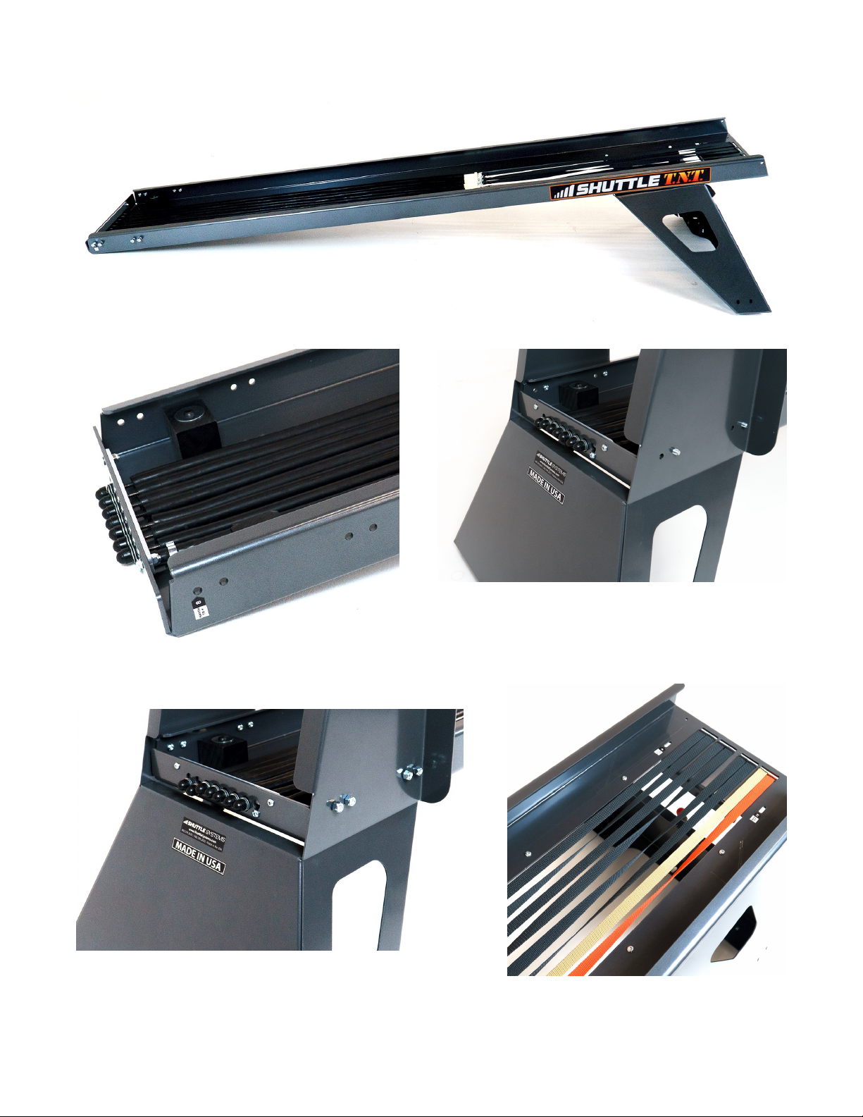
Shuttle TNT User manual
Other Shuttle Fitness Equipment manuals

Shuttle
Shuttle BALANCE User manual

Shuttle
Shuttle MiniPress User manual

Shuttle
Shuttle MVP Elite Plus User manual

Shuttle
Shuttle Shuttle Recovery User manual

Shuttle
Shuttle MVP User manual

Shuttle
Shuttle BALANCE User manual

Shuttle
Shuttle TNT User manual

Shuttle
Shuttle Ultimate User manual

Shuttle
Shuttle MVP User manual

Shuttle
Shuttle BALANCE User manual