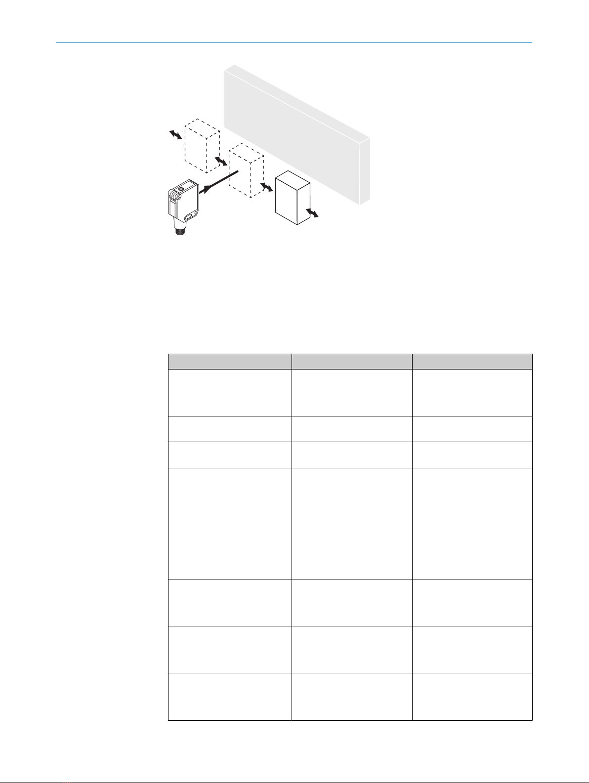
SICK GRTE18 24 Series User manual

OPERATING INSTRUCTION
GRTE18
Round photoelectric sensors

Described product
GR18
GRTE18
Manufacturer
SICK AG
Erwin-Sick-Str. 1
79183 Waldkirch
Germany
Production location
Legal information
This work is protected by copyright. Any rights derived from the copyright shall be
reserved for SICK AG. Reproduction of this document or parts of this document is
only permissible within the limits of the legal determination of Copyright Law. Any modi‐
fication, abridgment or translation of this document is prohibited without the express
written permission of SICK AG.
The trademarks stated in this document are the property of their respective owner.
© SICK AG. All rights reserved.
Original document
This document is an original document of SICK AG.
2006/42/EC
NO
SAFETY
8016953.1ABM / 2020-12-21 | SICK
Subject to change without notice 3

Contents
1 General safety notes......................................................................... 5
2 Notes on UL approval........................................................................ 5
3 Correct use......................................................................................... 5
4 Commissioning.................................................................................. 5
4.1 Check the application conditions............................................................ 5
4.2 Mounting................................................................................................... 7
4.3 Electronics................................................................................................. 8
4.4 Alignment.................................................................................................. 8
4.5 Adjustment................................................................................................ 9
5 Troubleshooting................................................................................. 10
6 Disassembly and disposal............................................................... 11
7 Maintenance...................................................................................... 11
8 Technical specifications................................................................... 11
8.1 Dimensional drawings.............................................................................. 12
CONTENTS
48016953.1ABM / 2020-12-21 | SICK
Subject to change without notice

1 General safety notes
■Read the operating instructions before commissioning.
■
Connection, mounting, and configuration may only be performed by trained
specialists.
■
2006/42/EC
NO
SAFETY
Not a safety component in accordance with the EU Machinery Directive.
■
Do not install the sensor at locations that are exposed to direct sunlight
or other weather influences, unless this is expressly permitted in the operating
instructions.
■These operating instructions contain information required during the life cycle of
the sensor.
2 Notes on UL approval
UL: Only for use in applications in accordance with NFPA 79. These devices shall be
protected by a 1 A fuse suitable for 30 V DC.
Adapters listed by UL with connection cables are available.
Enclosure type 1.
3 Correct use
The GRTE18 is an opto-electronic photoelectric proximity sensor (referred to as "sensor"
in the following) for the optical, non-contact detection of objects, animals, and persons.
If the product is used for any other purpose or modified in any way, any warranty claim
against SICK AG shall become void.
Energetic photoelectric proximity sensor
4 Commissioning
4.1 Check the application conditions
Check the application conditions: Adjust the sensing range and the remission capability
of the object according to the corresponding diagram [H] (x = sensing range, y =
operating reserve).
During this process, an object can only be detected in front of a background if the
remission capability of the object is significantly higher than that of the background or if
the distance between the object and the background is sufficiently long.
GENERAL SAFETY NOTES 1
8016953.1ABM / 2020-12-21 | SICK
Subject to change without notice 5

1
mm
(inch)
20
(0.79)
40
(1.57)
60
(2.36)
80
(3.15)
100
(3.94)
120
(4.72)
140
(5.51)
100
10
Operating reserve
Distance in mm (inch)
123
Figure 1: H: Sensing range 115 mm
1
mm
(inch)
100
(3.94)
200
(7.87)
300
(11.81)
400
(15.75)
500
(19.69)
600
(23.62)
100
10
Operating reserve
Distance in mm (inch)
123
Figure 2: H: Sensing range 550 mm
4 COMMISSIONING
68016953.1ABM / 2020-12-21 | SICK
Subject to change without notice

0 200
(7.87)
400
(15.75)
600
(23.62)
800
(31.5)
1,000
(39.37)
100
10
1
Operating reserve
Distance in mm (inch)
2
1
3
Figure 3: H: Sensing range 800 mm
4.2 Mounting
Mount the sensor using a suitable mounting bracket (see the SICK range of acces‐
sories).
Observe the maximum permissible tightening torque of the sensor of 2.0 Nm for
metal/0.9 Nm for plastic [K].
Figure: K: GRTE18-x24x7
Figure: K: GRTE18-x24x2
COMMISSIONING 4
8016953.1ABM / 2020-12-21 | SICK
Subject to change without notice 7

4.3 Electronics
The sensors must be connected in a voltage-free state (VS = 0 V). The information in the
graphics [B] must be observed, depending on the type of connection:
– Male connector connection: pin assignment
– Cable: core color
+ (L+)
Q
- (M)
brn
wht
blu
blk
1
2
3
Q
4
Figure: B: GRTE18-x24xx
+ (L+)
Q
- (M)
brn
wht
blu
Q
blk
Figure: B: GRTE18-x11xx, -x12xx
Only apply voltage/switch on the power supply (VS > 0 V) once all electrical connections
have been completed. The green LED indicator lights up on the sensor.
Explanations of the connection diagram (Graphic B):
Switching outputs Q and /Q (according to Graphic B):
GRTE18-P (PNP: load -> M)
GRTE18-N (NPN: load -> L+)
4.4 Alignment
Align the sensor with the object. Select the position so that the red emitted light beam
hits the center of the object. You must ensure that the optical opening (front screen) of
the sensor is completely clear [see figure 4].
Figure 4: Alignment
4 COMMISSIONING
88016953.1ABM / 2020-12-21 | SICK
Subject to change without notice

4.5 Adjustment
y
x
Figure: F
Sensor with potentiometer:
The sensitivity (sensing range) is adjusted with the potentiometer (type: 270°). Clock‐
wise rotation: sensitivity (sensing range) increased; counterclockwise rotation: sensitiv‐
ity (sensing range) reduced. We recommend placing the switching state in the object, e.
g., see graphic F. Once the sensitivity has been adjusted, the object is removed from the
path of the beam. The switching output changes (see graphic C).
The sensor is adjusted and ready for operation. Refer to graphics C and G to check the
function. If the switching output fails to behave in accordance with graphic C, check
application conditions. See section Fault diagnosis.
Q
(PNP)
(NPN)
Q
q1
0
q
1
0
1
0
1
0
Figure: C
COMMISSIONING 4
8016953.1ABM / 2020-12-21 | SICK
Subject to change without notice 9

Figure: G
5 Troubleshooting
The Troubleshooting table indicates measures to be taken if the sensor stops working.
Table Fault diagnosis
LED indicator/fault pattern Cause Measures
Green LED does not light up No voltage or voltage below
the limit values
Check the power supply,
check all electrical connec‐
tions (cables and plug connec‐
tions)
Green LED does not light up Voltage interruptions Ensure there is a stable power
supply without interruptions
Green LED does not light up Sensor is faulty If the power supply is OK,
replace the sensor
Yellow LED flashes Sensor is still ready for oper‐
ation, but the operating condi‐
tions are not ideal
Check the operating condi‐
tions: Fully align the beam
of light (light spot) with the
object. / Clean the optical sur‐
faces . / Readjust the sensi‐
tivity (potentiometer) / Check
sensing range and adjust
if necessary, see „Check
the application conditions“,
page 5.
Yellow LED lights up, no object
in the path of the beam
Excessive background remis‐
sion
Check changes to the back‐
ground. Reduce the sensitivity
of the sensor or use sensors
with background suppression
Object is in the path of the
beam, yellow LED does not
light up
Sensitivity is set too low or dis‐
tance between the sensor and
the object is too long
Increase the sensing range,
take note of the distance
between the sensor and the
background
Object is in the path of the
beam, yellow LED does not
light up
Remission capability of the
object is insufficient
Increase the sensing range,
take note of the distance
between the sensor and the
background
4 COMMISSIONING
10 8016953.1ABM / 2020-12-21 | SICK
Subject to change without notice

6 Disassembly and disposal
The sensor must be disposed of according to the applicable country-specific regula‐
tions. Efforts should be made during the disposal process to recycle the constituent
materials (particularly precious metals).
NOTE
Disposal of batteries, electric and electronic devices
•According to international directives, batteries, accumulators and electrical or
electronic devices must not be disposed of in general waste.
•The owner is obliged by law to return this devices at the end of their life to the
respective public collection points.
•
WEEE: This symbol on the product, its package or in this document,
indicates that a product is subject to these regulations.
7 Maintenance
SICK sensors are maintenance-free.
We recommend doing the following regularly:
•Clean the external lens surfaces
•Check the screw connections and plug-in connections
No modifications may be made to devices.
Subject to change without notice. Specified product properties and technical data are
not written guarantees.
8 Technical specifications
GRTE18-xxx1x GRTE18-xxx4x GRTE18-xxx6x
Recommended sensing range for the best performance 5 ... 100 mm 10 ... 400 mm 10 ... 800 mm
Sensing range max. 3 ... 115 mm1) 5 ... 550 mm 5 ... 1,000 mm
Light spot diameter/distance 8 mm / 100 mm 9 mm / 400 mm 45 mm / 800 mm
Supply voltage UBDC 10 ... 30 V2) DC 10 ... 30 V2) DC 10 ... 30 V2)
Ripple
Output current Imax. 100 mA 100 mA 100 mA
Current consumption
Switching frequency 500 / s3) 500 / s3) 500 / s3)
Max. response time < 1 ms4) < 1 ms4) < 1 ms4)
Enclosure rating IP67 IP67 IP67
Protection class III5) III5) III5)
Circuit protection A, B, D6) A, B, D6) A, B, D6)
DISASSEMBLY AND DISPOSAL 6
8016953.1ABM / 2020-12-21 | SICK
Subject to change without notice 11

GRTE18-xxx1x GRTE18-xxx4x GRTE18-xxx6x
Ambient operating temperature -25 °C ... +55 °C -25 °C ... +55 °C -25 °C ... +55 °C
1) Object with 90 % remission (based on standard white DIN 5033)
2) Limit values. UB connections reverse-polarity protected. Residual ripple max 5 VPP
3) With light / dark ratio 1:1
4) Signal transit time with resistive load
5) Reference voltage DC 50 V
6) A = UB-connections reverse polarity protected
B = inputs and output reverse-polarity protected
D = outputs overcurrent and short-circuit protected
8.1 Dimensional drawings
Figure 5: GRTE18-xxxx2
Figure 6: GRTE18-xxxx7
8 TECHNICAL SPECIFICATIONS
12 8016953.1ABM / 2020-12-21 | SICK
Subject to change without notice

Beschriebenes Produkt
GR18
GRTE18
Hersteller
SICK AG
Erwin-Sick-Str. 1
79183 Waldkirch
Deutschland
Fertigungsstandort
Rechtliche Hinweise
Dieses Werk ist urheberrechtlich geschützt. Die dadurch begründeten Rechte bleiben
bei der Firma SICK AG. Die Vervielfältigung des Werks oder von Teilen dieses Werks
ist nur in den Grenzen der gesetzlichen Bestimmungen des Urheberrechtsgesetzes
zulässig. Jede Änderung, Kürzung oder Übersetzung des Werks ohne ausdrückliche
schriftliche Zustimmung der Firma SICK AG ist untersagt.
Die in diesem Dokument genannten Marken sind Eigentum ihrer jeweiligen Inhaber.
© SICK AG. Alle Rechte vorbehalten.
Originaldokument
Dieses Dokument ist ein Originaldokument der SICK AG.
2006/42/EC
NO
SAFETY
14 8016953.1ABM / 2020-12-21 | SICK
Subject to change without notice

Inhalt
9 Allgemeine Sicherheitshinweise..................................................... 16
10 Hinweise zur UL Zulassung.............................................................. 16
11 Bestimmungsgemäße Verwendung............................................... 16
12 Inbetriebnahme................................................................................. 16
12.1 Einsatzbedingungen prüfen..................................................................... 16
12.2 Montage.................................................................................................... 18
12.3 Elektronik.................................................................................................. 19
12.4 Ausrichtung............................................................................................... 19
12.5 Einstellung................................................................................................. 20
13 Störungsbehebung............................................................................ 21
14 Demontage und Entsorgung............................................................ 22
15 Wartung.............................................................................................. 22
16 Technische Daten.............................................................................. 22
16.1 Maßzeichnungen...................................................................................... 23
INHALT
8016953.1ABM / 2020-12-21 | SICK
Subject to change without notice 15

9 Allgemeine Sicherheitshinweise
■Lesen Sie vor der Inbetriebnahme des Geräts die Betriebsanleitung.
■
Der Anschluss, die Montage und die Konfiguration des Geräts dürfen nur
von geschultem Fachpersonal vorgenommen werden.
■
2006/42/EC
NO
SAFETY
Bei diesem Gerät handelt es sich um kein sicherheitsgerichtetes Bauteil im
Sinne der EU-Maschinenrichtlinie.
■
Installieren Sie den Sensor nicht an Orten, die direkter Sonneneinstrahlung
oder sonstigen Wettereinflüssen ausgesetzt sind, ausser dies ist in der Betriebs‐
anleitung ausdrücklich erlaubt.
■Die vorliegende Betriebsanleitung enthält Informationen, die während des Lebens‐
zyklus der Lichtschranke benötigt werden.
10 Hinweise zur UL Zulassung
UL: Nur zur Verwendung in Anwendungen gemäß NFPA 79. Diese Geräte müssen mit
einer für 30V DC geeigneten 1A-Sicherung abgesichert werden.
Von UL gelistete Adapter mit Anschlusskabeln sind verfügbar.
Enclosure type 1.
11 Bestimmungsgemäße Verwendung
Die GRTE18 ist ein optoelektronischer Reflexions-Lichttaster (im Folgenden Sensor
genannt) und wird zum optischen, berührungslosen Erfassen von Sachen, Tieren und
Personen eingesetzt. Bei jeder anderen Verwendung und bei Veränderungen am Pro‐
dukt verfällt jeglicher Gewährleistungsanspruch gegenüber der SICK AG.
Energetischer Reflexionslichttaster
12 Inbetriebnahme
12.1 Einsatzbedingungen prüfen
Einsatzbedingungen prüfen: Schaltabstand und Remissionsvermögen des Objektes mit
dem zugehörigen Diagramm [vgl. H] abgleichen. (x = Schaltabstand, y = Funktionsre‐
serve).
Dabei kann ein Objekt vor einem Hintergrund nur detektiert werden, wenn das Remissi‐
onsvermögen des Objektes deutlich größer ist als das Remissionsvermögen des Hinter‐
grundes oder der Abstand zwischen Objekt und Hintergrund ausreichend groß ist.
9 ALLGEMEINE SICHERHEITSHINWEISE
16 8016953.1ABM / 2020-12-21 | SICK
Subject to change without notice

1
mm
(inch)
20
(0.79)
40
(1.57)
60
(2.36)
80
(3.15)
100
(3.94)
120
(4.72)
140
(5.51)
100
10
Operating reserve
Distance in mm (inch)
123
Abbildung 7: H: Sensing range 115 mm
1
mm
(inch)
100
(3.94)
200
(7.87)
300
(11.81)
400
(15.75)
500
(19.69)
600
(23.62)
100
10
Operating reserve
Distance in mm (inch)
123
Abbildung 8: H: Sensing range 550 mm
INBETRIEBNAHME 12
8016953.1ABM / 2020-12-21 | SICK
Subject to change without notice 17

0 200
(7.87)
400
(15.75)
600
(23.62)
800
(31.5)
1,000
(39.37)
100
10
1
Operating reserve
Distance in mm (inch)
2
1
3
Abbildung 9: H: Sensing range 800 mm
12.2 Montage
Den Sensor an einen geeigneten Befestigungswinkel montieren (siehe SICK-Zube‐
hör-Programm).
Maximal zulässiges Anzugsdrehmoment des Sensors von 2,0 Nm für Metall / 0,9 Nm
für Kunststoff beachten [vgl. K].
Abbildung: K: GRTE18-x24x7
Abbildung: K: GRTE18-x24x2
12 INBETRIEBNAHME
18 8016953.1ABM / 2020-12-21 | SICK
Subject to change without notice

12.3 Elektronik
Anschluss der Sensoren muss spannungsfrei (VS = 0 V) erfolgen. Je nach Anschlussart
sind die Informationen in den Grafiken [vgl. B] zu beachten:
– Steckeranschluss: Pinbelegung
– Leitung: Adernfarbe
+ (L+)
Q
- (M)
brn
wht
blu
blk
1
2
3
Q
4
Abbildung: B:GRTE18 -x24xx
+ (L+)
Q
- (M)
brn
wht
blu
Q
blk
Abbildung: B: GRTE18-x11xx, -x12xx
Erst nach Anschluss aller elektrischen Verbindungen die Spannungsversorgung (VS > 0
V) anlegen bzw. einschalten. Am Sensor leuchtet die grüne Anzeige-LED.
Erläuterungen zum Anschlussschema (Grafik B):
Schaltausgänge Q bzw. /Q (gemäß Grafik B):
GRTE18-P (PNP: Last -> M)
GRTE18-N (NPN: Last -> L+)
12.4 Ausrichtung
Sensor auf Objekt ausrichten. Positionierung so wählen, dass der rote Sendelichtstrahl
in der Mitte des Objekts auftrifft. Es ist darauf zu achten, dass die optische Öffnung
(Frontscheibe) des Sensors vollständig frei ist [siehe Abbildung 10].
Abbildung 10: Ausrichtung
INBETRIEBNAHME 12
8016953.1ABM / 2020-12-21 | SICK
Subject to change without notice 19

12.5 Einstellung
y
x
Abbildung: F
Sensor mit Potentiometer:
Mit dem Potentiometer (Art: 270°) wird die Empfindlichkeit (Schaltabstand) eingestellt.
Drehung nach rechts: Erhöhung der Empfindlichkeit (Schaltabstand), Drehung nach
links: Verringerung der Empfindlichkeit (Schaltabstand). Wir empfehlen, den Schaltab‐
stand in das Objekt zu legen, z. B. siehe Grafik F. Nachdem die Empfindlichkeit ein‐
gestellt worden ist, das Objekt aus dem Strahlengang entfernen. Der Schaltausgang
ändert sich (siehe Grafik C).
Sensor ist eingestellt und betriebsbereit. Zur Überprüfung der Funktion Grafik C und G
heranziehen. Verhält sich der Schaltausgang nicht gemäß Grafik C, Einsatzbedingungen
prüfen. Siehe Abschnitt Fehlerdiagnose.
Q
(PNP)
(NPN)
Q
q1
0
q
1
0
1
0
1
0
Abbildung: C
12 INBETRIEBNAHME
20 8016953.1ABM / 2020-12-21 | SICK
Subject to change without notice
This manual suits for next models
6
Table of contents
Languages:
Other SICK Accessories manuals

SICK
SICK RFU61 Series User manual

SICK
SICK TiM3 Series User manual

SICK
SICK MultiPulse WTB4-3P2100S13 User manual

SICK
SICK MPS-G User manual

SICK
SICK W26 User manual

SICK
SICK PowerProx WTT12L User manual

SICK
SICK GRSE18V User manual

SICK
SICK D 35 Series User manual

SICK
SICK WS34 User manual

SICK
SICK WTB4FP MultiSwitch User manual

SICK
SICK KTX Prime KTX-WB91141259ZZZZ User manual

SICK
SICK WSE4F User manual

SICK
SICK LMS100 User manual

SICK
SICK GRTE18V User manual

SICK
SICK PSS Prime User manual

SICK
SICK WS26 User manual

SICK
SICK WT24-2 Series User manual

SICK
SICK DC12-24V User manual

SICK
SICK GTE20 User manual

SICK
SICK NAV310 User manual