1 Safety notes
■Read the operating instructions before commissioning.
■
Connection, mounting, and setting may only be performed by skilled per‐
son.
■Not a safety component in accordance with the EU Machinery Directive.
■Power supply: Class 2
Enclosure type 1
■When commissioning, protect the device from moisture and contamination.
■These operating instructions contain information required during the life cycle of
the sensor.
2 Intended use
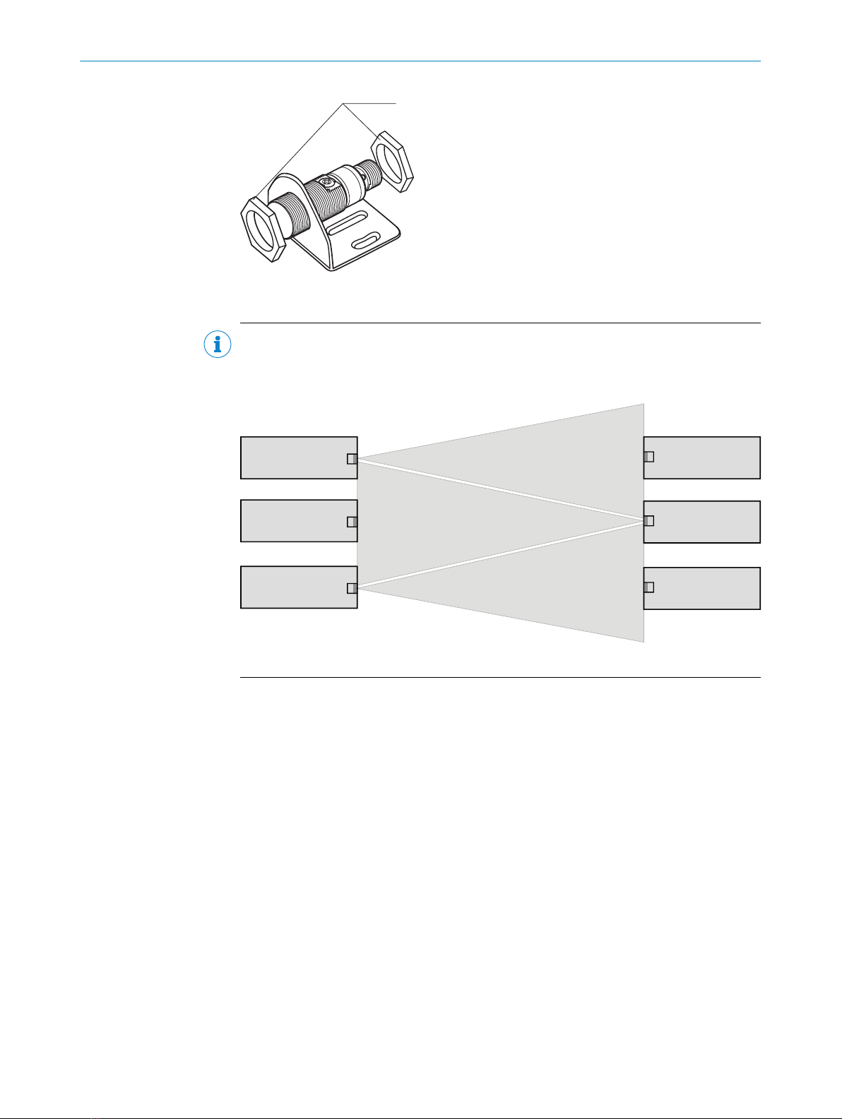
The GRSE18(S)V is an opto-electronic through-beam photoelectric sensor (referred to
as “sensor” in the following) for the optical, non-contact detection of objects, animals,
and persons. A sender (WS) and a receiver (WE) are required for operation. If the prod‐
uct is used for any other purpose or modified in any way, any warranty claim against
SICK AG shall become void.
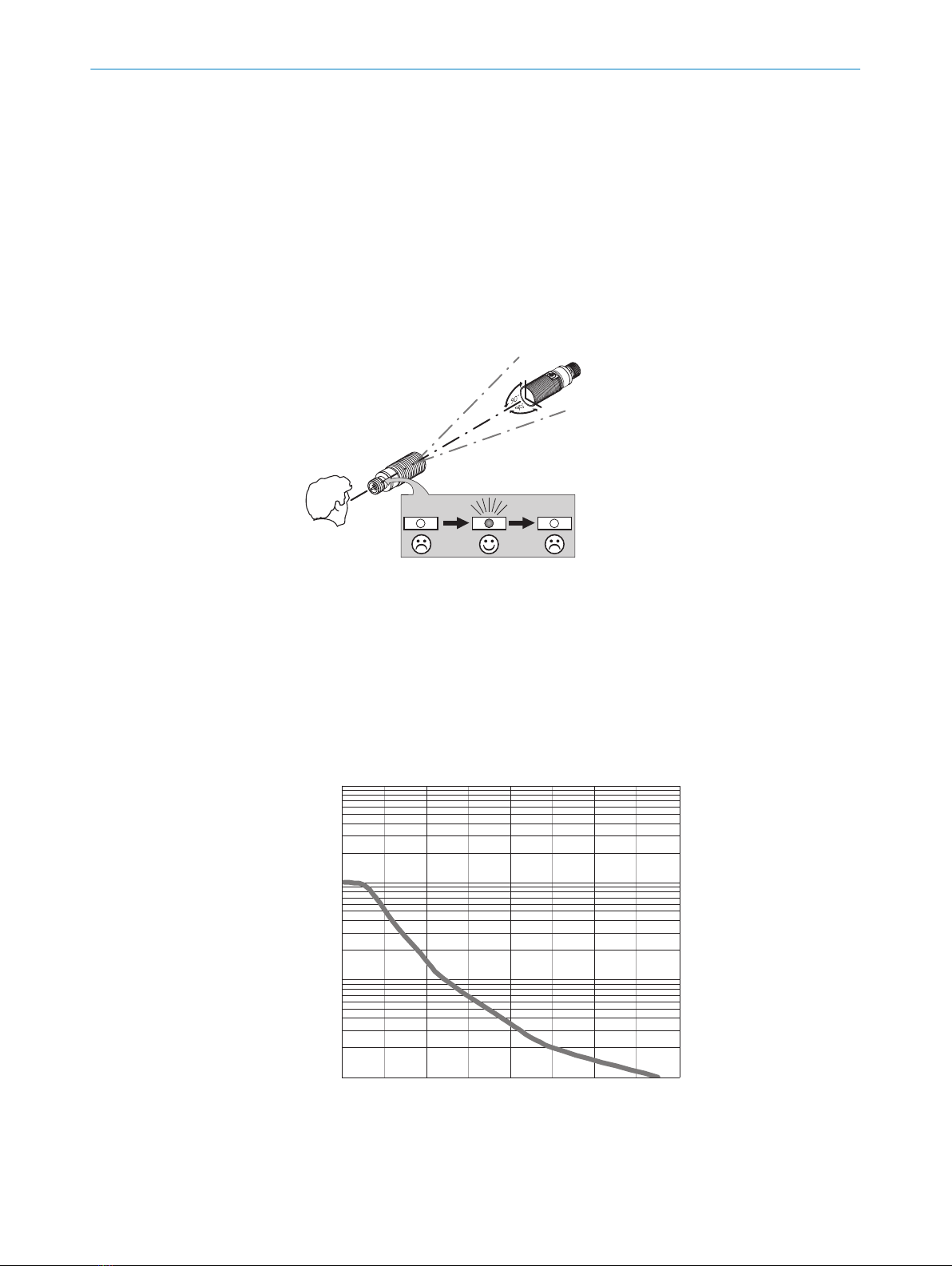
3 Operating and status indicators
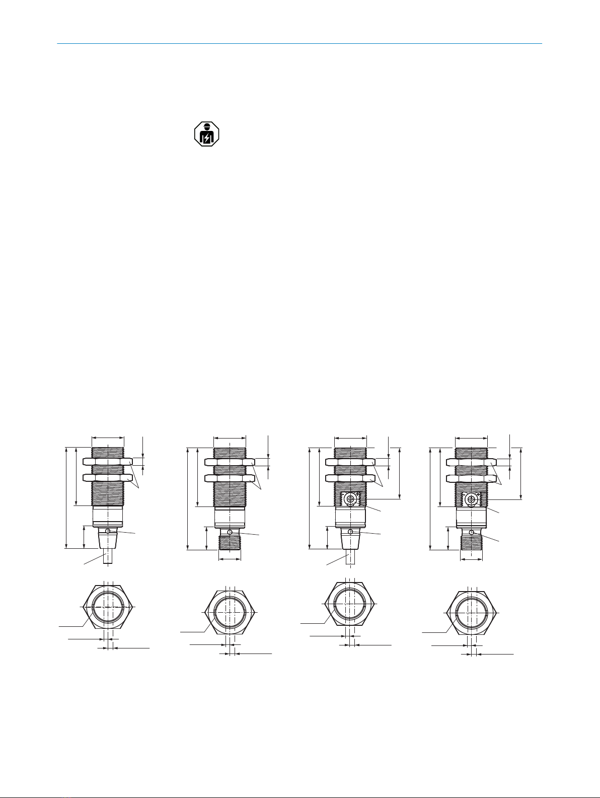
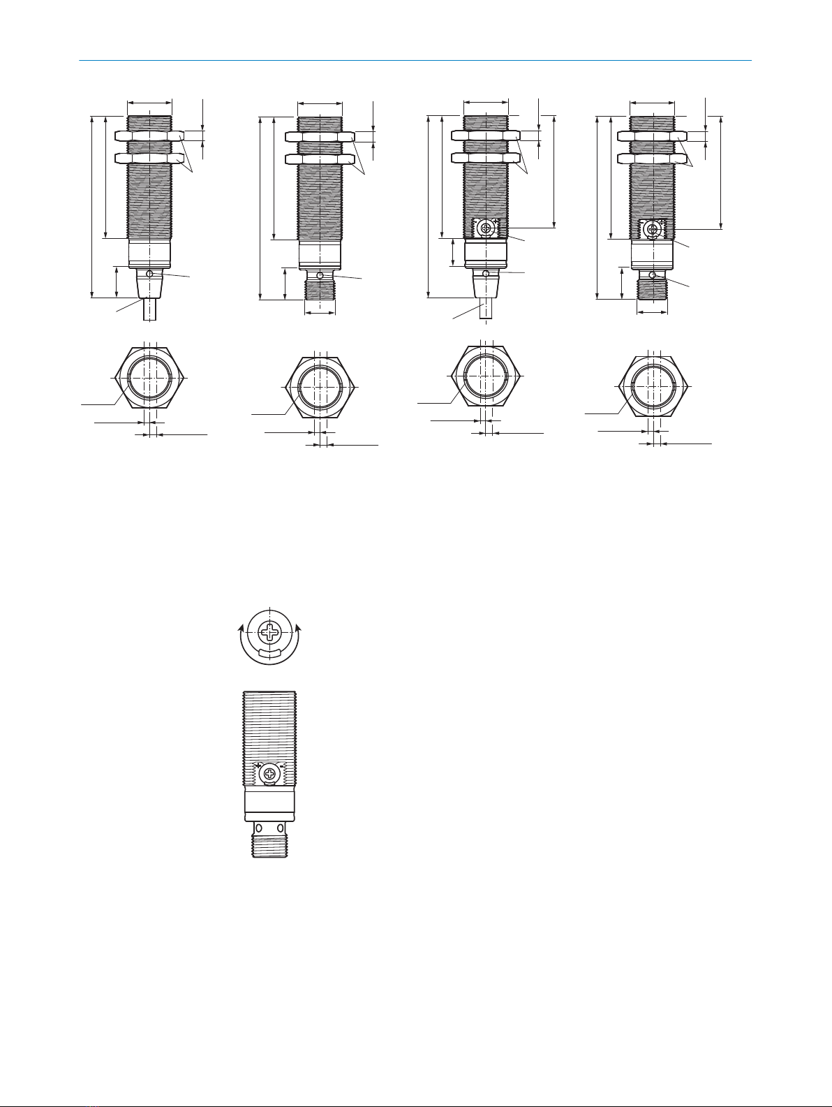
Table 1: Dimensional drawings
55.9 (2.2)
M18x1
31.7 (1.25)
4
(0.16)
12.9
(0.51)
2
2.8 (0.11)
2.2 (0.09)
3
67
5
1
M18x1
Figure 1: Short variant, con‐
necting cable
55.9 (2.2)
31.7 (1.25)
4
(0.16)
12.9
(0.51)
M12x1
M18x1
2
3
5
1
2.8 (0.11)
2.2 (0.09)
67
M18x1
Figure 2: Short variant, M12
male connector
27.8 (1.09)
55.9 (2.2)
31.7 (1.25)12.9
(0.51)
4
(0.16)
M18x1
2
3
4
5
1
2.8 (0.11)
2.2 (0.09)
67
M18x1
Figure 3: Short variant, potenti‐
ometer, connecting cable
12.9
(0.51)
4
(0.16)
55.9 (2.2)
31.7 (1.25)
27.8 (1.09)
M12x1
M18x1
2
3
4
5
1
2.8 (0.11)
2.2 (0.09)
67
M18x1
Figure 4: Short variant, potenti‐
ometer, M12 male connector
SAFETY NOTES 1
8021182 | SICK
Subject to change without notice 5