manuals.online logo
Brands
  1. Home
  2. •
  3. Brands
  4. •
  5. Siemens
  6. •
  7. Circuit Breaker
  8. •
  9. Siemens 3WN6 User manual

Siemens 3WN6 User manual

1
3WN6
Betriebsanleitung/Operating Instructions Bestell-Nr./Order No.: 3ZX1812-0WX36-4EA0 / 9239 9830 422 0-
Alle Rechte vorbehalten. All rights reserved. Tous droits réservés. Reservados todos los derechos.
Tutti i diritti sono riservati. Alla rätter förbehålls.
© Siemens AG 1997
Abschließvorrichtung gegen Verfahren 3WX3667-4J.00
Locking device against racking
Verrouillage de déplacement
Dispositivo de cierre contra desplazamiento
Dispositivo di blocco di movimentazione
Låsanordning mot process
Packungsinhaltüberprüfen /Checkcontentsofpack/Vérificationducontenudel’emballage/Comprobarelcontenido
del paquete / Controllare il contenuto dell’imballo / Kontroll av förpackningens innehåll
6
45
1
11
89
27
13
12 14
310
1 Schlüsseltaster (je nach bestellter Ausführung) /
Key-operated pushbutton (according to version ordered) /
Interrupteur à clé à position instable (suivant le modèle commandé)
Pulsador de llave (según la ejecución pedida)
Blocco a chiave (a seconda dell’esecuzione ordinata)
Nyckelströmställare (allt efter beställt utförande)
2, 3 Schloß (je nach bestellter Ausführung) / Lock (according to version
ordered) / Serrure (suivant le modèle commandé) / Cierre (según la
ejecución pedida) / Serratura (a seconda dell’esecuzione ordinata) /
Lås (allt efter beställt utförande)
4 Bügel / Bracket / Languette / Estribo / Archetto / Bygel
5 Bügel / Bracket / Languette / Estribo / Archetto / Bygel
6 Rohr / Tube / Tube / Tubo / Tubo / Rör
7 Distanzstück / Spacer / Entretoise / Pieza distanciadora / Distanziatore
/ Distansstycke
8 Federblech/ Springplate /Tôle-ressort /Chapa oscilante/ Lamieraper
molle / Fjäderplåt
9 Isolierung / Insulation / Isolation / Aislamiento / Isolante / Isolering
10 Druckplatte / Pressure plate / Plaque de serrage / Placa de presión /
Piastra di tenuta / Tryckplatta
11 Gewindestift / Threaded pin / Vis sans tête / Tornillo prisionero / Perno
filettato / Gängtapp
12 Zylinderschraube/Cheese-headscrew/Visàtêtecylindrique/Tornillo
cilíndrico / Vite a testa cilindrica / Skruv med cylindriskt huvud
13 Bohrschablone / Drilling jig / Gabarit de perçage / Plantilla de taladros
/ Maschera di foratura / Borrschablon
14 Spreizniet / Body-bound rivet / Rivet expansible / Remache expansible
/ Chiodo a espansione / Expandernit
1x
1x
1x
1x
1x
1x
1x
1x
1x
1x
1x
1x
2x
1x
1x
1x
Ronis-Protec, ProfaluxIkon, CES, BKS, OMR
2
ATTENTION !
Tension électrique dangereuse!
Tension de ressort dangereuse!
Avant le début des travaux, mettre l'appareil
hors tension et le condammner dans cette
position.
Interveniruniquementsurl’appareilenposition
d’ouverture et lorsque le dispositif d’accumula-
tiond’énergieparressortsestdétendu(voirpage3).
Le non-respect de ces mesures de sécurité
peutentraînerlamort,desblessuresgravesou
des dommages matériels importants.
Installation et montage uniquement par des
personnes qualifiées.
ATTENZIONE !
Tensione elettrica pericolosa!
Molle precariche!
Primadiiniziareilavori,assicurarsichel’appa-
recchio non sia in tensione e che non sia
possibile una reinserzione accidentale.
Lavorare soltanto a interruttore disinserito e a
molle scariche.
La mancata osservanza di tali norme può pro-
vocare incidenti mortali, gravi lesioni alle per-
sone e ingenti danni materiali.
L’installazione e il montaggio devono essere
effettuatiesclusivamentedapersonalespecia-
lizzato!
GEFAHR !
Gefährliche Spannung!
Gefährlicher Federspeicher!
Vor Beginn der Arbeiten Gerät spannungsfrei
schaltenundgegenWiedereinschaltensichern.
NurbeiausgeschaltetemSchalterundentspann-
tem Federspeicher arbeiten (siehe Seite 3).
Bei Nichtbeachtung können Tod, schwere
Körperverletzung oder erheblicher Sachscha-
den die Folge sein.
Einbau und Montage nur durch Fachpersonal!
¡PELIGRO!
¡Tension peligrosa!
¡Resorte peligroso!
Antesdeiniciarlostrabajoshayquedesconec-
tarelaparatoyasegurarlocontrareconexiones.
Trabajar únicamente con el interruptor desco-
nectadoyelresortedestensado(véasepágina
3).
La inobservancia de esta advertencia puede
causarlamuerte,graveslesionescorporaleso
altos daños materiales.
¡Montaje sólo por personal experto!
DANGER !
Hazardous voltage!
Hazardous spring pressure!
Before beginning work on the unit, switch it to a
deenergizedstateandsecureitagainstreactivation.
Work only with the circuit-breaker switched off
and the spring discharged (see page 3).
Non-observance can result in death, severe
personal injury or substantial property damage.
Onlyqualified personnelmay performinstalla-
tion and assembly work.
FARA!
Farlig elektrisk spänning!
Farlig fjäderspänning!
Innanarbetenapåbörjasskallapparatenkopp-
lasspänningsfriochsäkrasmotåterinkoppling.
Arbeta endast vid frånkopplad brytare och av-
spänd fjäder (se sidan 3).
Om detta inte iakttas kan död, svåra kropps-
skador eller betydande materielskador vara
följden.
Installering och montering endast av fack-
personal!
Deutsch
Español English
Italiano Français
Svenska
3
möjligt tillstånd: brytaren Till brytaren Från brytaren Till
fjädern avspänd fjädern spänd fjädern spänd
manövreringsföljd: Från Till - Från Från - Till - Från
SchalterinTrennstellungfahren/Movingcircuit-breakertodisconnectedposition/Déplacerledisjoncteurenposition
de sectionnement / Desplazar el interruptor a la posición de seccionamiento / Portare l’interruttore in posizione di
sezionato / Köra brytaren till skiljeläge
Trenn
Disconn
Kurbel stecken und Schalter in Trennstellung fahren (Positionsanzeige) /
Plug in the crank and pull breaker into disconnected position (position indicator) /
Engager la manivelle et déplacer le disjoncteur en position de sectionnement
(indication de position) /
Insertar la manivela y desplazar el interruptor a la posición de seccionamiento
(indicación de posición) /
Inserire la manovella e manovare l’interruttore in posizione di sezionato (indicatore
di posizione) /
Sätt i veven och kör brytaren till skiljeläge (positionsindikering)
AUS-Tasterdrücken,gleichzeitigSchieber
öffnen / Press OFF button, simultaneous
open the sleeve / Enfoncer le bouton
ARRET et ouvrir en même temps la
coulisse / Pulsar DES y abrir el pasador
simultáneamente / Premere il pulsante
OFF e aprire contemporaneamente la
saracinesca / Tryck på FRÅN-knappen,
öppna samtidigt sliden.
Schalter ausschalten, Federspeicher entspannen / Switching off the circuit-breaker and relieving the energy store /
Ouverture du disjoncteur, désarmement du ressort d’accumulation d’énergie / Desconectar el interruptor,
destensar el acumulador de energía por resorte / manovrare l´interruttore in OFF scaricare le molle di carica /
Koppla ifrån brytaren, lossa fjäderspänningen
Estado posible: Interruptor Con Interruptor Des Interruptor Con
Resorte destensado Resorte tensado Resorte tensado
Secuencia de maniobra: Des Con - Des Des - Con - Des
possibile stato: interruttore in ON interruttore in Out interruttore in ON
molle scariche molle cariche molle cariche
sequenza di manovra: Off On - Off Off - On - Off
OK
OK
OK
möglicher Zustand: Schalter Ein Schalter Aus Schalter Ein
Federspeicher entspannt Federspeicher gespannt Federspeicher gespannt
Betätigungsreihenfolge: Aus Ein - Aus Aus - Ein - Aus
Possible state: Circuit-breaker On Circuit-breaker Off Circuit-breaker On
Energy store relieved Energy store tensioned Energy store tensioned
Actuation sequence: Off On - Off Off - On - Off
Etat possible : disjoncteur fermé disjoncteur ouvert disjoncteur fermé
ressort désarmé ressort armé ressort armé
Séquence opératoire : ouverture ouverture - fermeture ouverture-fermeture-ouverture
➀
➁➀
➂
➁
Svenska Italiano Español Français English Deutsch
4
Bedienpult abnehmen / Lift off front panel / Dépose du panneau de commande / Desmontar el panel de control /
Rimuovere il pannello frontale di comando / Ta bort manövertavlan
15.2
Größe 2 / Size 2 /
Taille 2 / Tamaño 2 /
Grandezza2/Storlek2
Schalter in Wartungsstellung ziehen /
Pull breaker into maintenance position /
Tirer le disjoncteur en position de maintenance /
Sacar el interruptor hasta la posición de mantenimiento /
Portare l’interruttore in posizione di manutenzione /
Dra brytaren till serviceläge
15
15.2
15.3
Achtung! Erst Kurbelloch schließen, dann Bedienpult ab-
nehmen!
Attention! Close off the crank hole before lifting off the
control panel.
Important! Fermer la coulisse l’ouverture pour manivelle
avant de déposer le panneau de commande.
¡Atención! ¡Cerrar primero la abertura de la manivela y
desmontar el panel de control después!
Attenzione!Chiudereilforodellamanovellaprimadiestrar-
re il pannello frontale di comando!
Varning!Stängförstvevhålet,tasedanbortmanövertavlan!
- Befestigungsschrauben (15.2) lösen (2 x)
- Handhebel (15.3) bis zum spürbaren Widerstand
nach vorn schwenken
- Bedienpult (15) nach vorn abziehen
- Undo fixing screws (15.2) (2 x)
- Swivel the hand lever (15.3) forward until tangible
resistance is felt
- Extract the control panel (15) towards you
- Retirer les vis de fixation (15.2) (2x)
- Basculer vers l'avant le levier à main (15.3) jusqu'à
rencontrer une résistance évidente
- Dégager le panneau de commande (15) en le tirant
ver l'avant
- Soltar los tornillos de fijación (15.2) (2x)
- Abatirla palanca manual(15.3) hacia delantehasta
notar resistencia
- Extraer el panel de control (15) hacia delante
- Allentare le viti di fissaggio (15.2) (2x)
- Abbassarelalevadicomando(15.3)finoadavvertire
una netta resistenza
- Asportare il pannello (15) tirandolo in avanti
- Lossa (2x) fästskruvarna (15.2)
- Svänghandspaken(15.3)framåttillsmotståndkänns
- Dra av manövertavlan (15) framåt
Deutsch
English
Italiano
Svenska Français
Español
5
Loch in Bedienpult bohren / Drilling hole in control panel / Perçage du panneau de commande / Taladrar el panel de
control / Forare il pannello frontale di comando
/ Borra hål i manövertavlan
- Bohrschablone (13) wie dargestellt an Bedienpult
(15) anlegen (auf Markierung (13.1) achten!)
- Lochmittelpunkte körnen
- Loch mit Ø 5 mm bohren
- Loch mit Ø 22 mm (Ikon, CES, BKS, OMR, Profalux)
bzw. mit Ø 23 mm (Ronis-Protec) wie dargestellt in
Bedienpult (15) bohren (erst vorbohren!)
- Place drilling jig (13) on control panel (15) as illus-
trated (Note mark (13.1))
- Centre-punch hole centres
- Drill 5 mm diameter hole
- Drill 22 mm diameter hole (Ikon, CES, BKS, OMR,
Profalux) or 23 mm diameter hole (Ronis-Protec) in
control panel (15) as illustrated (drill pilot hole be-
forehand!)
Ø 22/23
13
13.1
Ø 5
13.1
15
Deutsch
English
- Colocarlaplantilladetaladros(13)sobreelpanelde
control (15) tal como se indica (¡Observar las mar-
cas (13.1)!)
- Punzonar los centros de los taladros
- Taladrar agujero de 5 mm Ø
- Taladrar agujero de 22 mm Ø (Ikon, CES, BKS,
OMR,Profalux) resp. 23mm Ø(Ronis-Protec)en el
paneldecontrol(15)talcomoseindica(¡Pretaladrar
primero!)
- Appliquer le gabarit de perçage (13) comme repré-
sentécontrelepanneaudecommande(15)(veillerau
repère (13.1) !)
- Pointer les centres des trous
- Percer le trou Ø 5 mm
- Percer le trou Ø 22 mm (Ikon, CES, BKS, OMR,
Profalux) ou Ø 23 mm (Ronis-Protec), comme repré-
senté (faire un avant-trou!)
Français
Español
- Lägg borrschablonen (13) på manövertavlan (15)
enligt figur (beakta markeringen (13.1)!)
- Körna hålets mittpunkt
- Borra hål med 5 mm Ø
- Borra hål med 22 mm Ø (Ikon, CES, BKS, OMR,
Profalux) resp. med 23 mm Ø (Ronis-Protec) i
manövertavlan (15) enligt figur (förborra först!)
- Accostare la maschera di foratura (13) al pannello
frontale di comando , procedendo come indicato in
figura (rispettare il segno tratteggiato (13.1)
- Punzonare il centro del foro
- Realizzare un foro di Ø 5mm
- Nel pannello frontale di comando (15) realizzare un
forodiØ22 mm(Ikon,CES,BSK,OMR,Profalux) oØ
23 mm (Ronis-Protec) procedendo come illustato in
figura (preforare!)
Italiano
Svenska
6
Schlüsseltaster in Bedienpult einbauen (Ikon, CES, BKS, OMR) /
Installing key-operated pushbutton in control panel (Ikon, CES, BKS, OMR) /
Montage de l’interrupteur à clé sur le panneau de commande (Ikon, CES, BKS, OMR) /
Montar el pulsador de llave en el panel de control (Ikon, CES, BKS, OMR) /
Montare il blocco a chiave nel pannello frontale di comando (Ikon, CES, BSK, OMR) /
Montera in nyckelströmställare i manövertavlan (Ikon, CES, BKS, OMR)
- Schlüsseltaster (1) durch Bedienpult (15) und Druck-
platte (10) stecken
- Schlüsseltaster(1)gegenDruckplatte(10)verdrehen
(Bild 2)
- Gewindestifte (11) in Druckplatte (10) gegen
Bedienpult (15) schrauben
Bild 1 / Fig. 1
1
10
11
11
Bild 2 / Fig. 2
11.1
15
- Insert key-operated pushbutton (1) through control
panel (15) and pressure plate
- Turnkey-operatedpushbuttonagainstpressureplate
(10) (Fig. 2)
- Screw threaded pins (11) into pressure plate (10)
against control panel (15)
- Introduire l’interrupteur à clé (1) à travers le panneau
de commande (15) et la plaque de serrage (10)
- Bloquer l’interrupteur à clé (1) en le tournant par
rapport à la plaque de serrage (10)
- Serrer les vis sans tête (11) de la plaque de serrage
(10) contre le panneau de commande (15)
-
Introducir el pulsador de llave (1) a través del panel
de control (15) y la placa de presión (10)
-
Girar el pulsador de llave (1) contra la placa de
presión (10) (fig. 2)
-
Enroscarlos tornillosprisioneros(11)enla placade
presión (10) contra el panel de control
- Inserire il blocco a chiave (1) nel pannello frontale di
comando (15) e nella piastra di tenuta (10)
- Ruotare il blocco a chiave (1) prremendolo contro la
piastra di tenuta (10)
- Serrare il perno filettato(11) nella piastra di tenuta (10)
premendolocontroilpannellofrontaledicomando(15)
-
Sticknyckelströmställaren(1)genommanövertavlan
(15) och tryckplattan (10)
-
Vrid nyckelströmställaren (1) mot tryckplattan (10)
(fig. 2)
-
Skruva i gängtappen (11) i tryckplattan (10) mot
manövertavlan (15)
Deutsch
English
Français
Español
Italiano
Svenska
7
Bügel an Schlüsseltaster montieren (Ikon, CES, BKS, OMR) /
Mounting bracket on key-operated pushbutton (Ikon, CES, BKS, OMR) /
Montage de la languette sur l’interrupteur à clé (Ikon, CES, BKS, OMR) /
Montar el estribo en el pulsador de llave (Ikon, CES, BKS, OMR) /
Montare l’archetto nel blocco a chiave (Ikon, CES; BSK; OMR) /
Montera bygel på nyckelströmställaren (Ikon, CES, BKS, OMR)
12
10
5
- Schlüssel (1.1) (Bild 1) nach links (gegen den Uhrzeiger-
sinn) drehen
- Bügel (5) wie dargestellt auf Schlüsseltaster (1) stecken
- Bügel (5) mit Zylinderschraube (12) sichern
(Anziehdrehmoment 0,5 ± 0,1 Nm)
- Turn key (1.1) (Fig. 1) counter-clockwise
- Place bracket (5) on key operated pushbutton (1) as
illustrated
- Secure bracket (5) with cheese-head screw (12)
(tightening torque 0.5 ± 0.1 Nm)
- Tourner la clé (1,1) (Fig. 1) vers la gauche (sens inverse
des aiguilles d’une montre)
- Placer la languette (5) comme représenté sur l’interrup-
teur à clé (1)
- Fixer la languette (5) avec la vis à tête cylindrique (12)
(couple de serrage 0,5 ± 0,1 Nm)
-
Girar la llave (1.1) (fig. 1) hacia la izquierda
-
Colocar el estribo (5) sobre el pulsador de llave (1) tal
como se indica
-
Asegurar el estribo (5) con tornillo cilíndrico (12)
(par de apriete 0,5 ± 0,1 Nm)
- Far ruotare la chiavetta (1.1) in senso antiorario (Fig. 1)
- Inserire l’archetto (5) nel blocco a chiave procedendo
come illustrato in figura
- Fissare l’archetto (5) con la vite a testa cilndrica (12)
(coppia di serraggio 0,5 + 0,1 Nm)
-
Vrid nyckeln (1.1) (fig. 1) åt vänster (moturs)
-
Sätt bygeln (5) på nyckelströmställaren (1) enligt bild
-
Säkrabygeln(5)medenskruvmedcylindriskthuvud(12)
(åtdragningsmoment 0,5 ± 0,1 Nm)
Svenska Italiano Español Français English Deutsch
8
Schloß in Bedienpult einbauen (Ronis-Protec, Profalux) / Installing lock in control panel (Ronis-Protec, Profalux) /
Montage de la serrure sur le panneau de commande (Ronis-Protec, Profalux) /
Montar el cierre en el panel de control
(Ronis-Protec, Profalux) / Montare la serratura nel pannello frontale di comando (Ronis-Protec, Profalux)
/
Montera in
lås i manövertavlan (Ronis-Protec, Profalux)
- Schloß (2) bzw. (3) mit Distanzstück (7) durch
Bedienpult (15) stecken
- Sicherungsmutter (2.2) bzw. (3.2) und Schloß (2)
bzw. (3) gegeneinander verdrehen, bis zwischen
Sicherungsmutter (2.2) bzw. (3.2) und Bedienpult
(15) der Abstand a = 1,5 ± 0,5 mm entsteht
- Darauf achten, daß die Abflachung (2.3) bzw. (3.3)
desSchlosses(2)bzw(3)senkrechtzumSteg(15.4)
des Bedienpultes (15) stehen und eine Kante der
Sicherungsmutter(2.2)bzw.(3.2)andiesemanliegt.
- Federblech(8)vonobenzwischenSicherungsmutter
(2.2) bzw. (3.2) und Bedienpult (15) klemmen
Hinweis:
Bei Schloß (3) (Ronis-Protec) muß der Mittenversatz
des Schließzylinders (3.4) wie dargestellt nach unten
zeigen.
- Insert lock (2) or (3) with spacer (7) through control
panel (15)
- Turn lock nut (2.2) or (3.2) and lock (2) or (3) in
oppositiontoone another untila distance of a= 1.5
±0.5mm isobtainedbetweenlock nut(2.2)or(3.2)
and control panel (15)
- Ensure that the flats (2.3) or (3.3) of the lock (2) or
(3) are perpendicular to the ridge (15.4) of the
control panel (15) and that one edge of the lock nut
(2.2) or (3.2) is in contact with the latter.
- Clampspringplate(8)fromabovebetweenlocknut
(2.2) or (3.2) and control panel (15)
Note:
In the case of lock (3) (Ronis-Protec), the eccentricity
of the lock barrel (3.4) must face downwards as illus-
trated.
7
15.4
15.4
15
2.1, 3.1
2, 3
8
2.2, 3.23.4
2.3, 3.3
- Engager la serrure (2) munie de l’entretoise (7) à
travers le panneau de commande (15)
- Visser l’écrou de fixation (2.2) ou (3.2) sur la serrure
(2) ou (3) jusqu’à ce qu’il reste un interstice a = 1,5 ±
0,5 mm entre l’écrou (2.2) ou (3.2) et le panneau de
commande (15)
- Veiller à ce que les méplats (2.3) ou (3.3) de la serrure
(2.2) ou (3.2) soient perpendiculaires à la membrure
(15.4)dupanneaudecommande(15)etàcequ’unearête
del’écroudefixation(2.2)ou(3.2)prenneappuicontreelle.
- Engager la tôle-ressort (8) par le haut entre l’écrou
(2.2) ou (3.2) et le panneau de commande (15)
Nota:
Pour la serrure (3) (Ronis-Protec), le désaxage du cylin-
dre de serrure (3.4) doit être dirigé vers le bas comme
représenté.
-
Introducir el cierre (2) resp. (3) con la pieza
distanciadora(17)atravésdelpaneldecontrol(15)
-
Girar la tuerca de retención (2.2) resp. (3.2) contra
elcierre(2)resp.(3)hastaqueladistancia“a”entre
latuerca de retención(2.2) resp. (3.2)y el panelde
control (15) sea de 1,5 ± 0,5 mm
-
Observarquelaparteplana(2.3)resp.(3.3)delcierre
(2) resp. (3) quede perpendicular al nervio (15.4) del
panel de control (15) y que un canto de la tuerca de
retención (2.2) resp. (3.2) quede adosado al mismo.
-
Introducir la chapa oscilante (8) desde arriba entre
latuercaderetención(2.2.)resp.(3.2)yelpanelde
control (15)
Nota:
En el cierre (3) (Ronis-Protec), el desplazamiento de
centros del cilindro de cierre (3.4) debe señalar hacia
abajo tal como se indica.
Deutsch
English
Français
Español
9
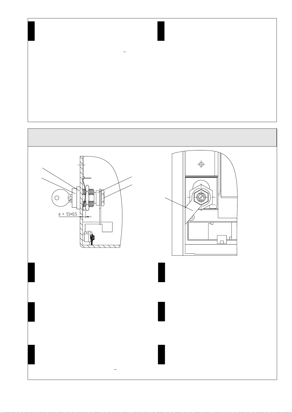
- Inserire la serratura (2) o (3) e il distanziatore nel
pannello frontale di comando (15)
- Far ruotare il dado di sicurezza (2.2) o (3.2) e la
serratura (2) in direzioni opposte fino a quando la
distanzatra dadodisicurezza (2.2)o (3.2)e ilpannello
frontale di comando non sarà pari a =1,5 + 0,5 mm
- Verificare che la superficie piana (2.3) o (3.3) della
serratura (2) o (3) sia perfettamente verticale alla
traversina (15.4) del pannello frontale di comando
(15) e che un angolo del dado di sicurezza (2.2) o
(3.2) poggi sulla stessa.
- Bloccarelalamierapermolle(8)traildadodisicurezza
(2.2) o (3.2) e il pannello frontale di comando (15)
Avvertenza:
se la serratura utilzzata è una (Ronois-Protec) (3) verifi-
care che la scanalatura centrale del cilindro di chiusura
(3.4) sia rivolta verso il basso come illustrato in figura.
-
Stick låset (2) resp. (3) med distansstycke (7)
genom manövertavlan (15)
-
Vridlåsmutter(2.2)resp.(3.2)ochlåset(2)resp.(3)
mot varandra tills mellan låsmutter (2.2) resp. (3.2)
ochmanövertavlan(15)avståndeta=1,5±0,5mm
uppstår
-
Manskallgeaktpåattavplaningen(2.3)resp.(3:3)
pålåset(2)resp.(3)stårlodrättmotstaget(15.4)på
manövertavlan (15) och att en kant på låsmuttern
(2.2) resp. (3.2) ligger mot detta.
-
Klämfastfjäderplåten(8)uppifrånmellanlåsmuttern
(2.2) resp. (3.2) och manövertavlan (15)
Observera:
För lås (3) (Ronis-Protec) måste mittförskjutningen på
låscylindern (3.4) peka nedåt enligt figuren.
Italiano
Svenska
Bügel an Schloß montieren (Ronis-Protec, Profalux) / Mounting bracket on lock (Ronis-Protec, Profalux) /
Montage de la languette sur la serrure (Ronis-Protec, Profalux) / Montar el estribo en el cierre (Ronis-Protec, Profalux) /
Montare l’archetto sulla serratura (Ronis-Protec, Profalux)
/
Montera bygel på låset (Ronis-Protec, Profalux)
- Turn key (2.1) or (3.1) counter-clockwise
- Push tube (6) onto lock (2) or (3)
- Pushbracket(4)ontolock(2)or(3)asillustratedand
secure with lock nut (2.5) or (3.5)
(tightening torque 3 ± 1 Nm)
- Schlüssel (2.1) bzw. (3.1) nach links (gegen den
Uhrzeigersinn) drehen
- Rohr (6) auf Schloß (2) bzw. (3) schieben
- Bügel (4) wie dargestellt auf Schloß (2) bzw. (3)
schieben und mit Sicherungsmutter (2.5) bzw. (3.5)
sichern (Anziehdrehmoment 3 ± 1 Nm)
2, 3
7
4
6
2.5, 3.5
-
Girar la llave (2.1) resp. (3.1) hacia la izquierda
-
Colocar el tubo (6) sobre el cierre (2) resp. (3)
-
Colocarelestribo (4) sobreel cierre (2) resp.(3) tal
comoseindicayasegurarlocontuercaderetención
(2.5) resp. (3.5) (par de apriete 3 ± 1 Nm)
- Tourner la clé (2.1) ou (3.1) vers la gauche (sens
inverse des aiguilles d’une montre)
- Engager le tube (6) sur la serrure (2) ou (3)
- Placer la languette (4) comme représenté sur la
serrure (2) ou (3) et la fixer avec l’écrou (2.5) ou (3.5)
(couple de serrage : 3 ± 1 Nm)
-
Vrid nyckeln (2.1) resp (3.1) åt vänster (moturs)
-
Skjut röret (6) på låset (2) resp. (3)
-
Skjut bygeln (4) enligt figur på låset (2) resp. (3) och
säkra med låsmutter (2.5) resp. (3.5)
(Åtdragningsmoment 3 ± 1 Nm)
- Farruotarelachiavetta(2.1)o(3.1)insensoantiorario
- Introdurre il tubo (6) nella serratura (2) o (3)
- Inserirel’archetto(4)nellaserraturaprocedendocome
indicato in figura e fissarlo con il dado di sicurezza
(2.3) o (3.5) (Coppia di serraggio 3 + 1 Nm)
Deutsch
English
Français
Español
Italiano
Svenska
10
Abschließende Arbeiten / Final operations / Travaux définitifs
/
Trabajos finales / Operazioni conclusive
/
Avslutnande
arbeten
5±0,5 Nm
- Bedienpult in umgekehrter Reihenfolge anbauen
Achtung! Erst Kurbelloch schließen, dann Bedienpult aufsetzen.
- Fit the control panel in reverse order
Caution! Close off the crank hole before fitting control panel.
- Remonter le panneau de commande en procédant dans l’ordre inverse du
démontage
Important!Fermerlacoulissedel’ouverturepourmanivelleavantderemonter
le panneau de commande.
-
Montar el panel de control en orden inverso
¡Atención!
¡Cerrar primero la abertura de la manivela y montar el panel de
control después!
- Rimontare il pannello frontale di comando procendo nell’ordine inverso
Attenzione! Incaso diinterruttori inesecuzione estraibilechiudere ilforo della
manovella prima di montare il pannello frontale di comando.
-
Montera in manövertavlan i omvänd ordningsföljd
Viktigt!
Stäng först vevhålet, sätt sedan på manövertavlan.
Isolierung montieren (Ikon, CES, BKS, OMR, Ronis-Protec, Profalux) /
Mounting insulation (Ikon, CES, BKS, OMR, Ronis-Protec, Profalux)
Montage de l’isolation (Ikon, CES, BKS, OMR, Ronis-Protec, Profalux) /
Montar el aislamiento (Ikon, CES, OMR, Ronis-Protec, Profalux) /
Montare l’isolante (Ikon, CES, BSK, OMP, Ronis-Protec, Profalux) /
Montera isolering (Ikon, CES, BKS, OMR, Ronis-Protec, Profalux)
- Isolierung(9)wie dargestellt anBedienpult(15)anlegen
- Spreizniet (14) durch Bedienpult (15) und Isolierung
(9) stecken
- Spreizniet(14)durcheindrückendesStiftes(14.1)sichern
14
9
15
14.1
- Placeinsulation(9)oncontrolpanel(15)asillustrated
- Insert body-bound rivet (14) through control panel
(15) and insulation (9)
- Securebody-boundrivet (14)bypushing inpin(14.1)
- Appliquer l’isolation (9) comme représenté contre le
panneau de commande (15)
- Enficher le rivet expansible (14) à travers le panneau
de commande (15) et l’isolation (9)
- Bloquer le rivet (14) en enfonçant la tige (14.1)
-
Colocarelaislamiento(9)enelpaneldecontrol(15)
tal como se indica
-
Introducir el remache expansible (14) a través del
panel de control (15) y el aislamiento (9)
-
Asegurar el remache expansible (14) apretando el
perno (14.1)
- Accostarel’isolante(9)alpannellofrontaledicomando(15)
- Inserire il chiodo a espansione (14) nel pannello
frontale di comando (15) e nell’isolante (9)
- Per fissare il chiodo a espansione (14) premere il
perno (14.1)
-
Läggisoleringen(9)enligtfigurpåmanövertavlan(15)
-
Stick expanderniten (14) genom manövertavlan
(15) och isoleringen (9)
-
Lås expanderniten (14) genom att trycka in stiftet
(14.1)
Deutsch
English
Français
Español
Italiano
Svenska
11
Leistungsschild des Schalters aktualisieren / Updating the rating plate / Actualisation de la plaque signalétique du
disjoncteur / Actualizar la placa de características del interruptor / Aggiornamento della targhetta di identificazione
dell’interruttore
/
Aktualisera brytarens märkskylt
Das Leistungsschild entsprechend Abbildung mit wisch- und wasserfestem Stift ändern. /
Using an indelible ink pen, alter the rating plate as shown in the figure. /
Modifier les indications de la plaque signalétique d’après la figure et le tableau ; utiliser un feutre indélébile. /
Modificar la placa de características según la figura con rotulador permanente. /
Modificare i dati di targa con un pennarello indelebile procedendo come indicato in figura. /
Ändra märkskylten enligt figur med gnugg- och vattenfast penna.
IEC 947-2
EN 60 947-2
DIN VDE 0660 T. 101
Cat. B
U
imp = 8 kV .....
.....
a.c.
d.c.
a.c.
d.c.
V
V
V
V
.....
.....
-
-
.....
..... .....
.....
-
-
M
400/415 V
2 2 2 a.c.
Y1
V
V
V
V
V
V
F1
F2 .....
.....
a.c.
d.c.
a.c.
d.c. .....
.....
.....
..... .....
.....
.....
.....
a.c.
d.c. .....
.....
-
-
-
-
-
-
F3
U <
.......
Ident.-Nr. ...............
1
2
1
2
1
2
..... A
3WN6 ... - ..... - .... Z =
3WN6
▲
Ein neues Leistungsschild ist unter Angabe der komplet-
tenSchalterbestellnummerimSchaltwerkbestellbar.Be-
stellnummer für das Leistungsschild: 3T 250 01705 001
A new rating plate can be ordered from the works by
specifying the complete circuit-breaker order number.
Order number for the rating plate: 3T 250 01705 001
S71 : CES
S72 : BKS
S73 : Ikon
S75 : Profalux
S76 : Ronis-Protec
S77 : OMR
Une nouvelle plaque signalétique peut être commandée
à l’usine. Indiquer le numéro de référence complet du
disjoncteur. N° de réf. pour plaque signalétique : 3T 250
01705 0015
Puede solicitarse una placa de características nueva
enfábricaindicandoelnúmerocompletodepedidodel
interruptor. Número de pedido de la placa: 3T 250
01705 001.
Èpossibileordinare una nuova targhettad’identificazio-
ne indicando il numero di ordinazione dell’interruttore.
Numerodi ordinazionedella targhettadi identificazione:
3T 250 01705 001.
En ny märkskylt kan beställas från firman under angi-
vandeavdetkomplettanumretförbrytaren.Beställnings-
nummer för märkskylten: 3T 250 01705 001.
English
Français
Español
Italiano
Svenska
Deutsch
12
Siemens Aktiengesellschaft Bestell-Nr./Order No.: 3ZX1812-0WX36-4EA0 / 9239 9830 422 0-
Bestell-Ort/Place of Order: A&D CD SE LK2 Berlin
Printed in the Federal Republic of Germany
AG 07.98 Kb De-En-Fr-Sp-It-Sv
Herausgegeben von
Bereich Automatisierungs- und Antriebstechnik
Niederspannungs-Schalttechnik
Schaltwerk Berlin
D - 13623 Berlin
Änderungen vorbehalten
Published by the
Automation & Drives Group
Control and Distribution
Schaltwerk Berlin
D - 13623 Berlin
FederalRepublicofGermany
Subject to change

Other manuals for 3WN6

38

Other Siemens Circuit Breaker manuals

Siemens 3VS16 User manual

Siemens

Siemens 3VS16 User manual

Siemens CLM0D Series Assembly instructions

Siemens

Siemens CLM0D Series Assembly instructions

Siemens 3VT Series User manual

Siemens

Siemens 3VT Series User manual

Siemens SIMATIC ET 200eco PN User manual

Siemens

Siemens SIMATIC ET 200eco PN User manual

Siemens HBLQR User manual

Siemens

Siemens HBLQR User manual

Siemens 3WL10 Series User manual

Siemens

Siemens 3WL10 Series User manual

Siemens 8DB10 User manual

Siemens

Siemens 8DB10 User manual

Siemens SIRIUS 3RV2 3 Series User manual

Siemens

Siemens SIRIUS 3RV2 3 Series User manual

Siemens 3AH47 series User manual

Siemens

Siemens 3AH47 series User manual

Siemens SIRIUS Star-Delta Combination S00 User manual

Siemens

Siemens SIRIUS Star-Delta Combination S00 User manual

Siemens UL 1066 User manual

Siemens

Siemens UL 1066 User manual

Siemens MP120DFP User manual

Siemens

Siemens MP120DFP User manual

Siemens AFCI Parts list manual

Siemens

Siemens AFCI Parts list manual

Siemens 3VT9100-4TN30 User manual

Siemens

Siemens 3VT9100-4TN30 User manual

Siemens 3VT9300-4WN00 User manual

Siemens

Siemens 3VT9300-4WN00 User manual

Siemens JG User manual

Siemens

Siemens JG User manual

Siemens SENTRON 3WL10 Technical Document

Siemens

Siemens SENTRON 3WL10 Technical Document

Siemens 8DA10 User manual

Siemens

Siemens 8DA10 User manual

Siemens 3VA20 JP Series User manual

Siemens

Siemens 3VA20 JP Series User manual

Siemens 3VL95 6 Series User manual

Siemens

Siemens 3VL95 6 Series User manual

Siemens 3ZW1012-0WL11-0HA1 User manual

Siemens

Siemens 3ZW1012-0WL11-0HA1 User manual

Siemens SINAMICS S120 User manual

Siemens

Siemens SINAMICS S120 User manual

Siemens N250X User manual

Siemens

Siemens N250X User manual

Siemens 3KL5040 User manual

Siemens

Siemens 3KL5040 User manual

Popular Circuit Breaker manuals by other brands

KEBCO COMBIVERT S6 Series installation manual

KEBCO

KEBCO COMBIVERT S6 Series installation manual

LEGRAND DMX-SP 4000 manual

LEGRAND

LEGRAND DMX-SP 4000 manual

Stanley MB556 user manual

Stanley

Stanley MB556 user manual

hager CE481J quick start guide

hager

hager CE481J quick start guide

Allis-Chalmers LA-600 Instruction book

Allis-Chalmers

Allis-Chalmers LA-600 Instruction book

Interlogix ATS1840 Installation sheet

Interlogix

Interlogix ATS1840 Installation sheet

OEZ MINIA MMR-X3-001-A230 Instructions for use

OEZ

OEZ MINIA MMR-X3-001-A230 Instructions for use

ABB Sace Emax UL Listed Installation, service and maintenance instructions

ABB

ABB Sace Emax UL Listed Installation, service and maintenance instructions

Eaton xComfort CSEZ-01/17 Assembly instructions

Eaton

Eaton xComfort CSEZ-01/17 Assembly instructions

GE Power Break II instructions

GE

GE Power Break II instructions

Eaton AMH-4.76-VR Instruction book

Eaton

Eaton AMH-4.76-VR Instruction book

ComAp InteliMains NT IM-NT-BB reference guide

ComAp

ComAp InteliMains NT IM-NT-BB reference guide

GODIAG GT103 manual

GODIAG

GODIAG GT103 manual

ABB Emax manual

ABB

ABB Emax manual

hager EP 071 User instructions

hager

hager EP 071 User instructions

ABB Tmax MIR-V manual

ABB

ABB Tmax MIR-V manual

WEG ACW400 manual

WEG

WEG ACW400 manual

Westinghouse DB-75 instructions

Westinghouse

Westinghouse DB-75 instructions

manuals.online logo
manuals.online logoBrands
  • About & Mission
  • Contact us
  • Privacy Policy
  • Terms and Conditions

Copyright 2025 Manuals.Online. All Rights Reserved.