manuals.online logo
Brands
  1. Home
  2. •
  3. Brands
  4. •
  5. Siemens
  6. •
  7. Controllers
  8. •
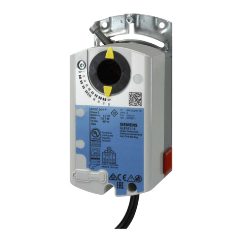
  9. Siemens OpenAir GEB 131.1E User manual

Siemens OpenAir GEB 131.1E User manual

CM2N4621en
16.03.2001
Siemens Building Technologies
Landis & Staefa Division
4
6
21
OpenAirTM
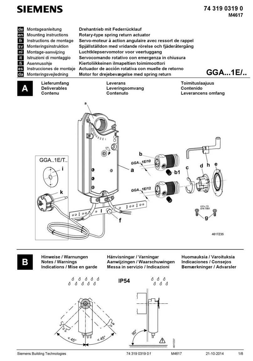
Airdamperactuators GEB...1
Rotary version, AC 24 V / AC 230 V
Electronic motor driven actuators for three-position and modulating control,
nominal torque 15 Nm, self-centering shaft adapter, mechanically adjustable
span between 0...90°, prewired with 0.9 m long connection cables.
Type-specific variations with adjustable offset and span for the positioning
signal, position indicator, feedback potentiometer, self-adaptation of the rotary
angle range, and adjustable auxiliary switches for supplementary functions.
This data sheet provides a brief overview of these actuators. Please refer to the
technical basics in CM2Z4621en for a detailed description as well as information on
safety, engineering notes, mounting and commissioning.
Use
•For damper areas up to 3 m2, friction-dependent.
•Suitable for modulating controllers (DC 0...10 V) or three-position controllers (e.g. for
outside air dampers).
•For dampers having two actuators on the same damper shaft (tandem-mounted
actuators or Powerpack).
Remarks
2/4
Siemens Building Technologies Air damper actuators GEB...1, rotary version CM2N4621en
Landis & Staefa Division 16.03.2001
Type summary
GEB.... 131.1E 132.1E 136.1E 331.1E 332.1E 336.1E 161.1E 163.1E 164.1E 166.1E
Control type Three-position control Modulating control
Operating voltage
AC 24 V XXX XXXX
Operating voltage
AC 230 V XXX
Positioning signal Y
DC 0...10 V XXXX
DC 2...10 V XX
DC 0...35 V with characteristic
function Uo, ∆UXX
Position indicator
U = DC 0...10 V XXXX
Feedback potentiometer 1kΩXX
Self-adaptation of
rotary angle range XXXX
Auxiliary switches (two) X X X X
Rotary direction switch XXXX
Powerpack (two actuators,
tandem-mounted) XXXXXX
Functions
Type GEB13..1 / GEB33...1 GEB16..1
Control type Three-position control Modulating control
Positioning signal with adjustable
characteristic function
DC 0...35 V with
Offset Uo = 0...5 V and
span ∆U = 2...30 V
Clockwise or counter-clockwise direction depends...
Rotary direction …the type of control. With no power applied, the
actuator remains in the respective position. ...the DIL switch setting clockwise / counter-
clockwise
Position indication: Mechanical Rotary angle position indication by using a position indicator.
Position indication: Electrical
The feedback potentiometer can be
connected to external voltage to indicate
the position.
Position indicator:
Output voltage U = DC 0...10 V is generated
proportional to the rotary angle. U depends on the
rotary direction of the DIL switch.
Auxiliary switch The switching points for auxiliary switches A and B can be set independent of each other
in increments of 5° within 0° to 90°.
Self-adaptation of
rotary angle range
When self-adaptation is active, the actuator
automatically determines the mechanical end
positions of the rotary angle range and maps the
characteristic function (Uo, ∆U) to the calculated
rotary angle range.
Powerpack Mounting two of the same actuator types on the
same damper shaft may result in a double torque. Not permitted.
Rotary angle limitation The rotary angle of the shaft adapter can be limited mechanically at increments of 5°.
Ordering
Potentiometer and auxiliary switches cannot be added in the field. For this reason,
order the type that includes the required options.
Individual parts such as position indicator and other mounting materials for the actuator
are not mounted on delivery.
Note
Delivery
3/4
Siemens Building Technologies Air damper actuators GEB...1, rotary version CM2N4621en
Landis & Staefa Division 16.03.2001
Accessories to functionally extend the actuators are available, e.g., rotary/linear sets
and weather protection cover; see data sheet N4697.
Technical data
Operating voltage / Frequency
Power consumption GEB13..1: Running
GEB16..1: Running
Holding
AC 24 V ±20 % / 50/60 Hz
4VA/3.5W
6VA/5.5W
1.5 W
Operating voltage / Frequency
Power consumption GEB33..1 AC 230 V ±10 % / 50/60 Hz
3VA/3W
Nominal torque
Maximum torque (blocked)
Nominal rotary angle / Max. rotary angle
Runtime for 90° rotary angle
15 Nm
30 Nm
90° / max. 95° ±2°
150 s (50 Hz) / 125 s (60 Hz)
Input voltage Y (wires 8-2)
Max. permissible input voltage DC 0...10 V / DC 2...10 V
DC 35 V
Input voltage Y (wires 8-2)
Non-adjustable characteristic function
Adjustable characteristic function Offset Uo
Span ∆U
DC 0...35 V
DC 0...10 V / DC 2...10 V
DC 0...5 V
DC 2...30 V
Output voltage U (cores 9-2)
Max. output current DC 0...10 V
DC ±1mA
Change of resistance (wires P1-P2)
Load 0...1000 Ω
<1W
Contact rating
Voltage (no mixed operation AC 24 V / AC 230 V)
Switching range for auxiliary switches
Setting increments
6 A resistive, 2 A inductive
AC 24...230 V
5°...90°
5°
Cross-section
Standard length 0.75 mm2
0.9 m
Degree of protection as per EN 60 529 (note mounting instructions) IP 54
Insulation class
AC 24 V, feedback potentiometer
AC 230 V, auxiliary switch
EN 60 730
lll
ll
Operation / Transport
Temperature
Humidity (non-condensing)
IEC 721-3-3 / IEC 721-3-2
−32...+55 °C / −32...+70 °C
< 95% r. h. / < 95% r. h.
Product safety: Automatic electrical controls for household and
similar use
Electromagnetic compatibility (EMC):
Immunity for all models, except GEB132.1x; GEB332.1x
Immunity for GEB132.1x; GEB332.1x
Emissions for all models
Conformity:
Electromagnetic compatibility
Low voltage directive
Conformity:
Australian EMC Framework
Radio Interference Emission Standard
EN 60 730-2-14
(Type 1)
EN 61 000-6-2
EN 50 082-1
EN 50 081-1
89/336/EEC
73/23/EEC
Radio Communication Act 1992
AS/NZS 3548
Actuator W x H x D (see "Dimensions")
Damper shaft: Round
Square
Min. shaft length
81 x 192 x 63 mm
6.4...20.5 mm
6.4...13 mm
20 mm
Without packaging: GEB1...1
GEB33..1 1kg
1.1 kg
Disposal
The document on technical basics and the environmental declaration provide
information on environmental compatibility and disposal of this device.
Accessories, spare
parts
AC 24 V supply
(SELV/PELV)
AC 230 V supply
Function data
Positioning signal for GEB16..1
Characteristic functions
for GEB161.1, GEB166.1
for GEB163.1, GEB164.1
Position indicator
for GEB16...1
Feedback potentiometer
for GEB132.1 / GEB332.1
Auxiliary switches
for GEB..6.1 / GEB164.1
Connection cables
Degree of protection of housing
Protection class
Environmental conditions
Standards and directives
Dimensions
Weight
4/4
Siemens Building Technologies Air damper actuators GEB...1, rotary version CM2N4621en
Landis & Staefa Division 16.03.2001
Internal diagrams
GEB13..1 / GEB33..1 GEB16..1
Three-position control Modulating control
4621G01
A
100%
0%
(Y2)
AC 0 V 0...1000 ΩAC 24 V...230 V / 6 (2) A
GEB13...
(a)
(G)
(Q12)
(Q14)
(Q24)
(Q22)
1S2S3S5S6
7P3S1S4
(Q11)
(Q21)
B
(Y1)
(b)
(c)
6P1P2
AC 24 V
M
4621G02
A100%
0%
(Y2)
AC 230 V 0...1000 ΩAC 24 V...230 V / 6 (2) A
GEB33...
(a)
(N)
(Q12)
(Q14)
(Q24)
(Q22)
4S2S3S5S6
7P3S1S4
(Q11)
(Q21)
B
(Y1)
(b)
(c)
6P1P2
M
DC 0...10 V / 2...10 V / 0...35 V
M
4621G03
A
100%
0%
DC 0...10 V
(G)
DC 0...10 V
(Y)
(G0)
(U)
(Q12)
(Q14)
(Q24)
(Q22)
29 S2 S3 S5 S6
18 S1S4
(Q11)
(Q21)
B
AC 24 V...230 V / 6 (2) A
GEB16...
AC 24 V
Cable
Pin Code No. Color
Abbreviation Meaning
Actuators AC 24V G1 red RD System potential AC 24 V
G0 2 black BK System neutral
Y1 6 purple VT Control signal AC 0 V, clockwise
Y2 7 orange OG Control signal AC 0 V, counter-clockwise
Y 8 gray GY Pos. signal DC 0...10 V, 2...10 V, 0...35 V
U 9 pink PK Position indication DC 0...10 V
Actuators AC 230V N 4 blue BU Neutral conductor
Y1 6 black BK Control signal AC 230 V, clockwise
Y2 7 white WH Control signal AC 230 V, counter-clockwise
Auxiliary switch Q11 S1 gray/red GY RD Switch A Input
Q12 S2 gray/blue GY BU Switch A Normally closed contact
Q14 S3 gray/pink GY PK Switch A Normally open contact
Q21 S4 black/red BK RD Switch B Input
Q22 S5 black/blue BK BU Switch B Normally closed contact
Q24 S6 black/pink BK PK Switch B Normally open contact
Positioner a P1 white/red WH RD Potentiometer 0...100 % (P1-P2)
b P2 white/blue WH BU Potentiometer pick-off
c P3 white/pink WH PK Potentiometer 100...0 % (P3-P2)
Dimensions
12
10.6 20
180
Dia.5
141
192 60
Dia.10.5
42
31.5
60
81
3030
3
19
113
2
Taptite
M6 x 16
GEB...1
15
168
Mounting bracket
4621M01en
Dia. 6.4...20.5
Square 6.4...13
Dimensions in mm
Cable labeling
ã
2000 Siemens Building Technologies Ltd. Subject to change

This manual suits for next models

10

Other Siemens Controllers manuals

Siemens OpenAir GMA 1 Series Installation guide

Siemens

Siemens OpenAir GMA 1 Series Installation guide

Siemens OpenAir GMA 1 Series User manual

Siemens

Siemens OpenAir GMA 1 Series User manual

Siemens SINUMERIK 802D sl Owner's manual

Siemens

Siemens SINUMERIK 802D sl Owner's manual

Siemens BT300 LonWorks Instructions for use

Siemens

Siemens BT300 LonWorks Instructions for use

Siemens RVP200/210 User manual

Siemens

Siemens RVP200/210 User manual

Siemens SIRIUS 3RF29-0KA Series User manual

Siemens

Siemens SIRIUS 3RF29-0KA Series User manual

Siemens CPU 410-5H Process Automation User guide

Siemens

Siemens CPU 410-5H Process Automation User guide

Siemens ICP-B6 Service manual

Siemens

Siemens ICP-B6 Service manual

Siemens Simatic S7-300 User manual

Siemens

Siemens Simatic S7-300 User manual

Siemens Simatic S7-300 User manual

Siemens

Siemens Simatic S7-300 User manual

Siemens Powermite 599 Series Owner's manual

Siemens

Siemens Powermite 599 Series Owner's manual

Siemens OpenAir GIB13.1 Series User manual

Siemens

Siemens OpenAir GIB13.1 Series User manual

Siemens ATC5300 User manual

Siemens

Siemens ATC5300 User manual

Siemens Acvatix SAX Series Operator's manual

Siemens

Siemens Acvatix SAX Series Operator's manual

Siemens Acvatix SAS31.03 User manual

Siemens

Siemens Acvatix SAS31.03 User manual

Siemens RVL469 User manual

Siemens

Siemens RVL469 User manual

Siemens SIRIUS 3RW3003 User manual

Siemens

Siemens SIRIUS 3RW3003 User manual

Siemens SIMATIC S5-100U User manual

Siemens

Siemens SIMATIC S5-100U User manual

Siemens SIMATIC S7-1200 User manual

Siemens

Siemens SIMATIC S7-1200 User manual

Siemens SIMATIC S7 User manual

Siemens

Siemens SIMATIC S7 User manual

Siemens SIRIUS 3RW40 5 User manual

Siemens

Siemens SIRIUS 3RW40 5 User manual

Siemens SQL36E series User manual

Siemens

Siemens SQL36E series User manual

Siemens SINAMICS G120 User guide

Siemens

Siemens SINAMICS G120 User guide

Siemens SSA911.02ZB User manual

Siemens

Siemens SSA911.02ZB User manual

Popular Controllers manuals by other brands

ELCOS CIM250/10 Instruction and user's manual

ELCOS

ELCOS CIM250/10 Instruction and user's manual

RNA ESR 2500 operating instructions

RNA

RNA ESR 2500 operating instructions

Stanley EX5500 Installation &  configuration guide

Stanley

Stanley EX5500 Installation & configuration guide

Smarteh LONGO LPC-2 user manual

Smarteh

Smarteh LONGO LPC-2 user manual

Comar Condensatori QSR6 user manual

Comar Condensatori

Comar Condensatori QSR6 user manual

LOXONE Valve Actuator Air quick guide

LOXONE

LOXONE Valve Actuator Air quick guide

gefran SIEIDrive ADV100 Quick start up guide

gefran

gefran SIEIDrive ADV100 Quick start up guide

Emerson Fisher 3025 instruction manual

Emerson

Emerson Fisher 3025 instruction manual

SICK UE 440 operating instructions

SICK

SICK UE 440 operating instructions

Playcore Colorado Time Systems WTTC-1 manual

Playcore

Playcore Colorado Time Systems WTTC-1 manual

Koch BVS20 Brief programming instructions

Koch

Koch BVS20 Brief programming instructions

GAI-Tronics 013-02-0096-001 installation instructions

GAI-Tronics

GAI-Tronics 013-02-0096-001 installation instructions

Allen-Bradley PowerFlex 400 Product information

Allen-Bradley

Allen-Bradley PowerFlex 400 Product information

Electro-Voice PWS-4 Technical specifications

Electro-Voice

Electro-Voice PWS-4 Technical specifications

ITOH DENKI POWER MOLLER HBM-604BN Technical document

ITOH DENKI

ITOH DENKI POWER MOLLER HBM-604BN Technical document

Mitsubishi Electric Q172CPU Programming manual

Mitsubishi Electric

Mitsubishi Electric Q172CPU Programming manual

Midea KJR-12B/DP(T) owner's manual

Midea

Midea KJR-12B/DP(T) owner's manual

Magnimage MIG-F4 user manual

Magnimage

Magnimage MIG-F4 user manual

manuals.online logo
manuals.online logoBrands
  • About & Mission
  • Contact us
  • Privacy Policy
  • Terms and Conditions

Copyright 2025 Manuals.Online. All Rights Reserved.