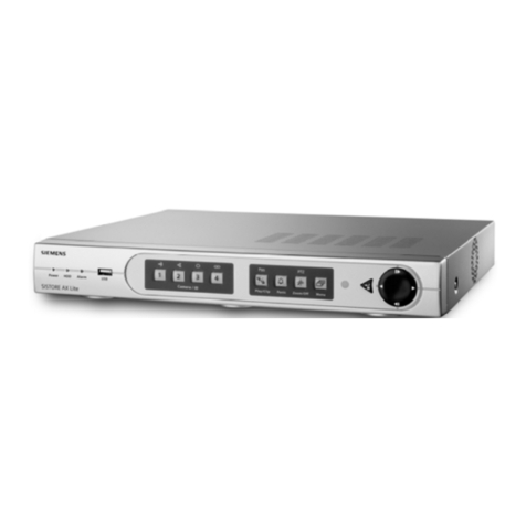
Siemens VideoRec Operating instructions

VideoRec
RA53-050.061.01.03.02 English
Replaces: RA53-050.061.01.02.02 08.95
Proprietary data, company confidential. All rights reserved.
Confié á titre de secret d’ entreprise. Tous droits resérvés.
Confiado como secreto industrial. Nos reservamos todos los derechos.
Copyright (C) Siemens AG 1994
RA
Service Instructions

Revisions
Siemens AG TDRA 1 RA53-050.061.01 VideoRec
Medizinische Technik Rev. 03 08.95
Chapter Page Rev.
all all 01
all all 02
all all 03

Table of Contents 0-1
Siemens AG TD RA 3 RA53-050.061.01 VideoRec
Medizinische Technik Rev. 03 08.95
Page
1 General Remarks 1-1
General Remarks/Function Information 1-1
Required Aids/Tools 1-2
2 Description of Assemblies 2-1
S-VHS Video Recorder (Sony) 2-1
SSI 22 VCR Interface 2-2
VSC 36 SHC Video Scan Converter, 50 or 60 Hz 2-3
Cabling Schematic 2-5
3 Troubleshooting 3-1
4 Repair 4-1
Replacing the Sony Video Recorder 4-1
Replacing the SSI22 VCR Interface 4-2
Replacing the Video Scan Converter 4-4
5 Adjustment 5-1
General Remarks 5-1
Adjusting the Amplitude Parameters for
VCR Record Mode 5-2
Illustration of the Principle Used for Record Mode 5-2
With HICOR: Adjusting the Amplitudes and Size/Position Parameters for
VCR Playback (Upscan, H Norm). 5-4
With Multistar T.O.P: Adjusting the Amplitudes and Size/Position
Parameters for VCR Playback (Upscan, H Norm). 5-6
With Polytron / Digicor: Adjusting the Amplitudes and Size / Position
Parameters for VCR Playback (Upscan, H Norm). 5-8
Adjusting the Cosine Enhancer 5-10
6 Changes Versus the Previous Edition 6-1

0-2 Table of Contents
Siemens AG TD RA 3 RA53-050.061.01 VideoRec
Medizinische Technik Rev. 03 08.95
Page

General Remarks 1-1
Siemens AG TD RA 3 RA53-050.061.01 VideoRec
Medizinische Technik Rev. 03 08.95
General Remarks 1
General Remarks/Function Information
●TheVideoReciscomposedof:
S-VHS Recorder (SVO-9500MD(P)with built-in parallelinterface.
ScanConverterVSC 36 SHC 50/60.
SSi22VCRinterfacewithcableset.
●WiththeVideoRec,NorH video signalscan be recordedonN-SVHSvideo
recorders(Sony).
●WithHvideo signals,adownscan selectiontakesplaceautomaticallyintheVSC36
SHCscanconverter.
●Playbacktakesplaceviatheupscan ofthe VSC 36SHC ontheH control room
monitor oron thecontrol room andexamination room monitors.
●The control ofautomatic exposure (cine/DCM fluorocan be jumpered)takesplace
over the SSI22 VCRinterface oftheX-raysystem(M96, M96C, system distributor)
●TheSSI22VCR interfaceis powered over the X-raysystemwith24V.
●Automaticmonitorswitch-overbytheinterface,andthereisalsoanautomatic
switch-overtoVCR playbackin theinterfacewhenthereis playbackofthe S-VHS
recorder.Ifradiationistriggered,themonitorsareswitchedovertotheX-raysystem
asadefaultsetting.
●NOTE:Ifcine is selectedwhiletheVCR is in theplaybackmode,thevideorecorder
isswitchedimmediatelytorecord!Thismeans that any scene beingplayedbackwill
bewrittenover!
●Warningsignalgenerator(intheSSI22VCR interface),
-whenthetape reachesthe end
-whenthereisno video cassette inserted
-whentheVCR powerisswitchedoff
-whentheVCR isoperatedmanuallyduringcine,awarningsignalissounded.
●WarningoutputoverX4,Pin6:
-canbe switched on/offusinga jumper,see paragraph entitled,Recording.
-attheend of the tape
-ifnovideocassetteisinserted
-iftheVCR power is switched off
-iftheinterface powerisswitchedoff
- ifamanualcontrolismadeat the VCR during automatic recording.
●ThepowerlinevoltagefortheVideoRecis230V;except for 60 Hz thevideorecorder
mustbeconnectedto120V.
●Forspareparts,seetheVideoComponentsSparePartsList,RA53-050.081.01...
●Note:whensettingupthevideorecorder,makesurethereisgoodaircirculation
aroundit.Theminimumspace between the VCR andthesidesof built-inconsolesor
othercomponentsmustbe at least3 cm.
Iftwovideorecordersareconfiguredina biplanesystem,topermitgoodheat
dissipation, under no circumstancesmay they be closer than3 cm to eachother, i.e.,
they may notbe placed next to each other in theoptinally available control console.
Howeveritispossibletoplaceoneon top of theother.
Payattentiontogoodaircirculation.
1-2 General Remarks
Siemens AG TD RA 3 RA53-050.061.01 VideoRec
Medizinische Technik Rev. 03 08.95
Required Aids/Tools
●Standardservicetoolkit,asdefinedin ARTD, Part 3
●Memoryoscilloscope,asdefinedinARTD,Part3
●Mavomonitor,asdefinedinARTD, Part 3
Part No. 97 02432 Y0526
●Digitalvoltmeter,asdefinedinARTD,Part3
●TVDynamicsTest
●BNC connector, Part No. 30 06 590
BNC
POS
BNC
NEG
BNC
NEG

Description of Assemblies 2-1
Siemens AG TD RA 3 RA53-050.061.01 VideoRec
Medizinische Technik Rev. 03 08.95
Description of Assemblies 2
S-VHS Video Recorder (Sony)
●RecordingofN video signalson S-VHS tapes.
●Playbackof N-recordedS-VHStapes.
●Canbe remotelycontrolledover a built-in 34-pininterface.
IMPORTANT:OnlytheS-VHRrecorder(Sony) shippedwithVideoRechas this
interface!
●The60Hz modelcanbe operated only at 120V!
* Note: The terminal resistor for the loop-through output must be set to ON.
Video input
from SSI / XX3 Video output
to SSI / XX4
REMOTE
Power connector socket
34-Pin i nterface
~ AC IN 75 Ohm terminal resistor *

2-2 Description of Assemblies
Siemens AG TD RA 3 RA53-050.061.01 VideoRec
Medizinische Technik Rev. 03 08.95
SSI 22 VCR Interface
●LEDdisplayofpower On.
●2xoptical video separation (required,because the video recordermay be operated
witha groundwireandgroundloops mustbeavoided),forinputand outputof the
videorecorder.
●Automaticcontrolofrecordfunctionof the video recorder,dependingon the X-ray
system.
●Controlof monitor switch-overand of upscanfunctionintheVSC 36 SHCwithvideo
recorderplayback.
●StartingwithSerialNo. 95391, a Cosinus Enhancer(edge enhancement)forVCR
recordingis integrated.
●Warningsignaloutputto X4Pin6. Output “only“ withselectionofrecord!
Monitoredfunctions:
Whenno cassetteis inserted.
Whenthetapeis at the end.
Whenthereisno power to the interface.
Iftherecorderis manually operatedduringan automaticrecording.
UptoSerialNo. 95334the transistorswitchesto ground!
StartingwithSerialNo. 95334or when usingthe repair/replacementprocedure,
whenthereisa warningground is sent out(viatransistor)withOK +24Vover
2.7kOhm.
●Forjumperingof thedifferentfunctions,seethe sectionon Repair.
Power switch
Power line connector
XX1 XX2
XX3 XX4 X1
X3 X4
X2
KVTR connector
(M96 or M96C)
VSC36 SHC
X2
Video recorder
34-pin interface
Video input
from video recorder
Video output
to video recorder
BAS IN
BAS OUT
Video output
to VSC 36 SHC
X3
Video input
from VSC 36 SHC
X7
Note: The spade connectors on the quick connectors above coax sockets XX1 and XX2 are used to connect the external
shielding of the triax cable. Connector X2 is not used.

Description of Assemblies 2-3
Siemens AG TD RA 3 RA53-050.061.01 VideoRec
Medizinische Technik Rev. 03 08.95
VSC 36 SHC Video Scan Converter, 50 or 60 Hz
●LED display of power ON.
●NOTE:two differentscannersare neededfor 50 and60 Hz video scanrates.
●Automaticrecognitionof H-linevideoinputsignalsandswitch-overto downscan or
bypasswithN video signals.
●Adaptationof the differentinput signalstoa 1V standardsignalforthevideo
recorderin thedownscan mode.
●Dependingon thecontrolby thevideorecorderor X-ray system
(viatheSSI22VCR interface):
UpscanmodeforVCR playback.
Monitorswitch-over toX-ray system or VCRplayback.
Adaptation of the 1Vpp video signals from the video recorder to HICOR monitors to
1.4Vpp for upscan.
X10
X9
X3 X4 X5 X6 X7 X8
Examination room monitor
HICOR output “Mon. 1“
SSI 22 XX1
Control room monitor
HICOR output “Mon. 2“
HICOR output “VCR“ or from
Examination room Live monitor in DIGICOR systems
SSI 22
XX2
Power switch
Power line connector
Note: The spade connectors on the quick connectors above coax sockets XX1 and XX2 are used to connect the external
X1 X2
SSI 22
X3
shielding of the triax cable. Connectors X1 and X10 are not used.

2-4 Description of Assemblies
Siemens AG TD RA 3 RA53-050.061.01 VideoRec
Medizinische Technik Rev. 03 08.95

Description of Assemblies 2-5
Siemens AG TD RA 3 RA53-050.061.01 VideoRec
Medizinische Technik Rev. 03 08.95
Cabling Schematic
*1 Warning signal output, see paragraph
“Description of Assemblies“, SSI 22 VCR Interface .
Digital System / TV
N or H, 50 or 60HzExamination room Control room
Jumper
VSC 36SHC
VCR Interface SSI22 M96 /M96C
System distributo
r
Ex. room Con. room
X8 X5 X4
X2
X9 X6 X3 X7
XX2 XX1 X3
XX4 XX3 X1
X4
IN
OUT 34-pin connector
Sony
SVO9500MD(P)
opt. video separation
fac. settings
fac. settings 7/8
7/8 = +24V
2 = Stand By
3 = Record
6 = Warning *1
1/9/10/11/12/13/
14/15 = Ground
ggg

2-6 Description of Assemblies
Siemens AG TD RA 3 RA53-050.061.01 VideoRec
Medizinische Technik Rev. 03 08.95

Troubleshooting 3-1
Siemens AG TD RA 3 RA53-050.061.01 VideoRec
Medizinische Technik Rev. 03 08.95
Troubleshooting 3
S-VHS Recorder, Sony SVO 9500 MD(P)
The recorder is thought of as a black box and must be replaced completely.
IMPORTANT: Every returned recorder must be accompnaied by a detailed description
of the malfunction!
SSI22 VCR Interface
No function or only partial function - check the power fuses on the rear of the unit (at
the power input) and check the internal fuses.
IMPORTANT: Every returned interface must be accompanied by a detailed description
of the malfunction!
VSC 36 SHC Scan Converter
No function or only partial function - check the power fuses on the rear of the unit (at
the power input) and check the internal fuses.
IMPORTANT: Every returned scanner must be accompanied by a detailed description
of the malfunction!
F301 F302
F 1
F101
F151
F251
F201
F 2
MainFuse Rückseite / rear side
F 1 F 2
MainFuse Rückseite / rear side

3-2 Troubleshooting
Siemens AG TD RA 3 RA53-050.061.01 VideoRec
Medizinische Technik Rev. 03 08.95

Repair 4-1
Siemens AG TD RA 3 RA53-050.061.01 VideoRec
Medizinische Technik Rev. 03 08.95
Repair 4
Replacing the Sony Video Recorder
●
NOTE: Only the model listed in the Spare Parts List
(RA53-050.081.01...) (additional interface) may be used.
Only an SVO 9500 MDP (Pal, 230 V) may be used with 50 Hz power
line systems.
Only an SVO 9500 MD (NTSC, 120 V) may be used with 60 Hz
power line systems.
●Connectthe video input/ output and interfacecables“as before”.
●Setthe75 Ohm terminationswitchto ON(noloop-throughmode), with connectionof
avideoprinterto OFF(terminationisin printer).
●Y-Enhancer:
Thevideo recorderis equippedwitha switchableY-Enhancer(edge enhancement
withplayback). Thisenhancer is setto ON whenshipped from the factory and must
beswitchedoff as follows:
CTL / MENU -set switchinthe “MENU” position.
ITEM - continueto press key until“4 EN-....”appears in the display.
DATA -presskey until“4 EN--OF” is set.
CTL / MENU -set switchback to the “CTR” position.

4-2 Repair
Siemens AG TD RA 3 RA53-050.061.01 VideoRec
Medizinische Technik Rev. 03 08.95
Replacing the SSI22 VCR Interface
Starting with Serial No. 95 334 a warning signal is output over socket X4, Pin 6
(used with MULTISTAR T.O.P configured with the cine option).
Spare parts have been upgraded.
When used with the Multistar T.O.P. or CARD III, it is always set to “ON“. Setting for
“only“ record or for fluoro and record see the Configuration Guide for
Multistar T.O.P. or the POLYDOROS IS Service Instruction for CARD III.
Cosine Enhancer:
Up to Serial No. 95 391 “several“ enhancers were built in; with these enhancers the
switch must be set to the “0 - position“ (off).
Starting with Serial No. 95 391, the Cosine Enhancer is fully functional; for adjust-
ment,see the chapter “Adjustment“.
No further adjustments are necessary.
Jumper Positions
Jumper Norm Function
X5
X6
X7
X8
X9
OFF
OFF
ON
OFF
ON
ON - No warning signal output with recording error.
ON-Playback on control rooml/examination room monitor.
OFF-Playback on control room monitor
ON- Cine/DCM/Acquisition recording only.
OFF- Fluoro and Cine/DCM/Acquisition recording.
OFF - No warning signal with recording error
OFF-Warning signal output when there is a recording error.
Always set to OFF
*1
*2
On - Warning signal when there is a recording error.
*1
*2

Repair 4-3
Siemens AG TD RA 3 RA53-050.061.01 VideoRec
Medizinische Technik Rev. 03 08.95
VCR - Interface SSI 22
.
Main fuse Rückseite / rear side
XXX X5
X6
X7
X8
X9
X 5/6/7/8/9
1231-2 OFF
2-3 ON
FINE - 0 - COARSE
COSINE ENHANCER
FINE - 0 - COARSE
COSINE ENHANCER
Switch
FINE - 0 - COARSE
COSINE ENHANCER
Je nach Seriennummer
depending on Serial No.
Power Supply Cosine Enhancer
Interface
OTV
OTV

4-4 Repair
Siemens AG TD RA 3 RA53-050.061.01 VideoRec
Medizinische Technik Rev. 03 08.95
Replacing the Video Scan Converter
Connect all inputs/outputs as they were previously connected.
Switch Positions
*Remove the parallel resistor to R17, see illustration.
J1 to J30 factory settings - specifications for conversion / size / position.
DIGICOR
with
control
room
monitor
DIGICOR
without
control
room
monitor
Polytron Hicor/
Multistar
T.O.P. Function
S2 OFF ON OFF ON Switchable terminal resistor for X4 input
S4/5 ON OFF ON OFF Loop-through of X4 input to X6 output
S6 OFF OFF OFF ON ON = Bypass Scanner with Power Off.
OFF =No Bypass with Power Off.
S7 OFF OFF OFF ON Terminal resistor for X5 input with
UP scan.
*Remove Remove Remove Leave Change of the potentiometer adjust-
ment range for DOWN Scan
F 1 F 2
MainFuse Rückseite / rear side
P1 P3
P5
Scan Converter VSC 36
P1 R17
Parallel resistor
S6 S2
S7 S4
S5 unter / below S4
ON - OFF
S2/4/5/6/7
(820 Ohm)
if no S5, then
S4 = S4/S5

Adjustment 5-1
Siemens AG TD RA 3 RA53-050.061.01 VideoRec
Medizinische Technik Rev. 03 10.95
Adjustment 5
General Remarks
Adjustment is divided into three sections:
VCR record mode
VCR playback mode
Cosine enhancer adjustment.
For adjustment, see below.
Note:
The Simomed H monitor has its own set of adjustment parameters for each norm.
This means that if necessary, every norm which is beingused must be adjusted (image
alignment and contrast)!
e.g. HICOR: With the HICOR, the 1249 lines/100 Hz (1023 lines/120 Hz) norm is used
for the monitor.
With the VideoRec, the 1249 lines/50 Hz (1023 lines/60 Hz) norm is used
for the monitor.
With bypass, the 1249 lines/50 Hz (1023 line/60 Hz) norm is used for the
monitor.
e.g. MULTISTAR T.O.P:
With a digital system, 2249 lines/60 Hz are used for the monitor,
With bypass, 1125 lines/60 Hz are used for the monitor (the same norm
for the monitor as with 2249 lines/60 Hz !!),
With the VideoRec, 1249 lines/50 Hz (1023 lines/60 Hz) are used for the
monitor.

5-2 Adjustment
Siemens AG TD RA 3 RA53-050.061.01 VideoRec
Medizinische Technik Rev. 03 10.95
Adjusting the Amplitude Parameters for
VCR Record Mode
Illustration of the Principle Used for Record Mode
●Ifa cosineenhancerisconfigured(see theChapter on Replacement),itmustbe
switchedoffduringthe adjustment(inthe 0position).
●Feed inthe SMPTE testpattern forthe digital system.
Ifa digitalsystem is not configured,a recordingof the TV dynamictest(recordmode)
canalso be used(field2L musthavethe max. amplitude).
●Adjustingthe outputamplitudes:
Connect the oscilloscope Channel1 to output X7using BNC connectors
(scanconverter),set200 mV,5 ms, Triggerint.Channel1
-Ifthereis “only“an Ninput,there is no adjustment.
- WithanN input and in theH backupmode (e.g.HICOR)etc. :
Measure the BA amplitude withthe N Norm and with theH Norm
UseP2 toadjust the S portionto 0.3V,+/-30mV.
UseP4 toadjust the BA portionto the same valueasforthe
NNorm,but max. 0.7V, +/- 30mV.
- With“only“the H Norm:
UseP2 toadjust the S portionto 0.3V,+/-30mV.
UseP4 toadjust the BA portionto 0.7V,+/-30mV.
ConnecttheoscilloscopeChannel1 to outputXX3 (VCR Interface)using
BNC connectors,set 200 mV, 5 ms,Trigger int. Channel 1
- Use potentiometer R151for VCR IN(VCR Interface) toadjust to
1V,+/-30mVBAS.
●Adjustmentof the downscan size/ position parameters(horizontalonly):
Ifthereis “only“the N input,thereisno adjustment.
WithaH input, carry out the adjustmentas follows if needed.
Correctadjustmentofthe upscansize/positionparametersisprerequisite,see
paragraph“Use.............: to adjust the amplitudeand size/positionparameters“!!
Thesetting can onlybe changedpriorto VCR recordand canonly be evaluatedwith
VCRplayback;changethe potentiometersettingonlyslightly!!
Use P6 to adjust the horizontal position,centered on the monitor.
Use P8 to adjust the horizontal size (witha circle,it must be round).
●Ifa cosineenhancerisconfigured,it must beswitchedbackon.
Digital System N Norm
H Norm N Norm
VCR
Scan Converter
X7 Interface
N and / or H Norm
OTV
XX1 XX3
VCR
Table of contents
Other Siemens DVR manuals

Siemens
Siemens DMS8000 Owner's manual

Siemens
Siemens SISTORE AX4 Lite 1000/100 Quick guide

Siemens
Siemens SISTORE AX9 User manual

Siemens
Siemens SISTORE AX8 1000/200 V4.0 User manual

Siemens
Siemens DMS8000 MP4 Series Quick guide

Siemens
Siemens SISTORE MX User manual

Siemens
Siemens SISTORE AX4 Lite 250/100 V2.0 User manual

Siemens
Siemens SISTORE AX9 250 User manual

Siemens
Siemens SISTORE AX8 250/100 V2.8 User manual

Siemens
Siemens SISTORE MX User manual