3
Before mounting the RCC-3/-3C/3F/-3FC,
remove the four nuts from the keyboard panel
and place them to one side. Carefully lift the
panel up and off the standoffs. Set the panel to
one side.
Consider the following when mounting the
backbox:
• Mounting height for visual and manual
access to the keyboard/display panel
• Weight and size of the enclosure
• Local mounting codes
1. Fasten the backbox securely to a clean, dry,
shock-free, and vibration-free surface using
the four mounting holes provided. Position
the backbox clear of obstructions so that the
door opens freely and the indicators and
controls are easily accessible.
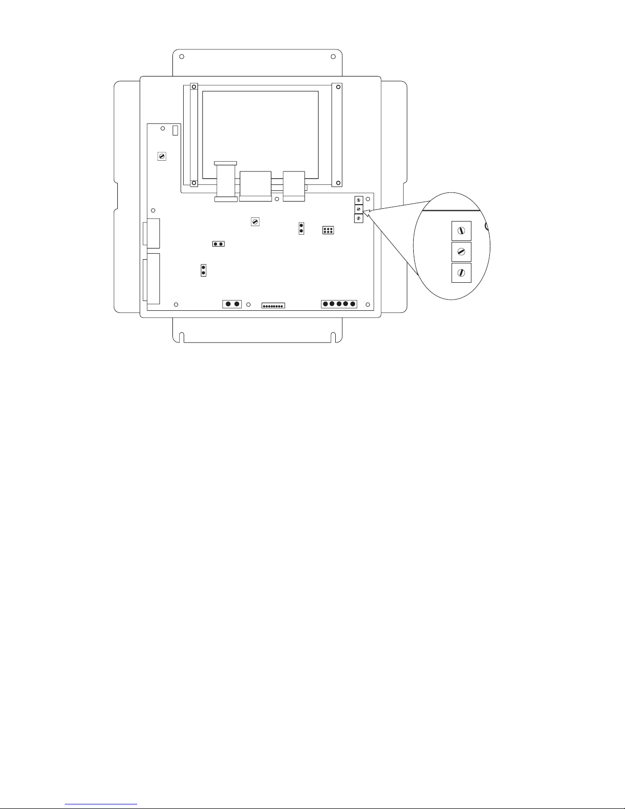
2. Set the Network Address for the RCC-3
using the three ten-position rotary switches
(S1, S2 and S3) located on the back of the
keyboard/display panel, as shown in Figure 3.
For example, to set the switches to address
248: set S1 to 2, set S2 to 4, and set S3 to 8.
The possible addresses for this module are
248, 259, 250, and 251.
Figure 3
Rear View of Keyboard/Display Panel in RCC-3/3F
NOTE:
There is no need to set supervision on the
RCC-3/-3C/3F/-3FC because it is, by default,
always supervised. No unsupervised
annunciators (MKB-1/-2/-3/-4) are allowed
at the same address as an RCC-3/-3C/3F/-
3FC. Unsupervised applications require the
use of the MKB-1/-2/-3/-4 and they must all
be set to the same address.
3. Pull all field wiring into the backbox and
dress the wiring to the approximate location
to which it will go.
4. Remove the connector plugs from J8. Attach
the wiring to the connector plugs in positions
1 and 2 for Style 4 (refer to Figure 4) and
positions 1, 2, 3 and 4 for Style 7 (refer to
Figures 5 and 6). Always connect position 5
to Chassis GND (Earth GND).
5. Remove the connector plugs from J12.
Attach the field wiring to the connector plugs,
making sure that position 1 on J12 is for
+24VDC and position 2 on J12 is for -24VDC
return.
6. To adjust the contrast and brightness of the
display, use pots VR1 and VR2 respectively,
located on the back of the keyboard /display
panel. (Refer to Figure 3.)
1
2
3
4
5
6
7
8
9
0
1
2
3
4
5
6
7
8
9
0
1
2
3
4
5
6
7
8
9
0
J3
J10
J11
S1
S2
S3
J12 J4 J8
J2 J1 J5
+_12345
NETWORKTO OPTION
MODULES
LCD KEYBOARD LEDS
BACKLIGHT
SERIAL
PRINTER
PARALLEL
PRINTER
1
1
11
1
1
2
11
VR1
CONTRAST
VR2
BRIGHTNESS
J6
J7
J9
J13
1
2
3
4
5
6
7
8
9
0
1
2
3
4
5
6
7
8
9
0
1
2
3
4
5
6
7
8
9
0
S1
S2
S3