Siko SG5 Operation manual
SG5 Datum 28.02.2014 Art. Nr. 83679 Änd. Stand 076/14 1
Kabelschuh
Messbereich
max. Auszugslänge
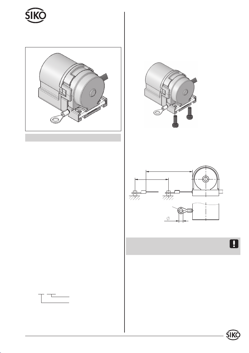
Abb. 2: Prüfung Auszugslänge
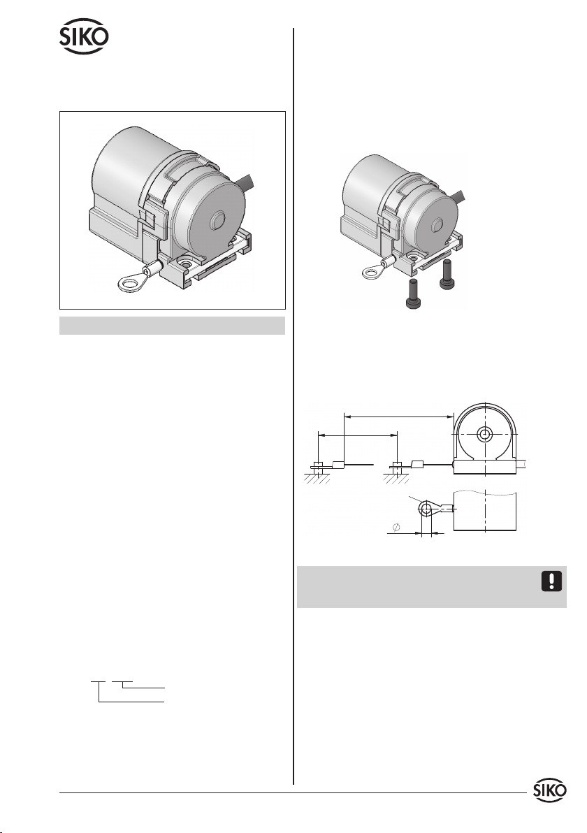
Abb. 1: Montage
DEUTSCH
1. Gewährleistungshinweise
• LesenSievorderMontageundderInbetriebnahme
diesesDokumentsorgfältigdurch.BeachtenSiezu
IhrereigenenSicherheitundderBetriebssicherheit
alle Warnungen und Hinweise.
• Ihr Produkt hat unser Werk in geprüftem und
betriebsbereitem Zustand verlassen. Für den
BetriebgeltendieangegebenSpezifikationenund
die Angaben auf dem Typenschild als Bedingung.
• Garantieansprüche gelten nur für Produkte der
Firma SIKO GmbH. Bei dem Einsatz in Verbindung
mitFremdproduktenbestehtfürdasGesamtsystem
kein Garantieanspruch.
• Reparaturen dürfen nur im Werk vorgenommen
werden. Für weitere Fragen steht Ihnen die Firma
SIKO GmbH gerne zur Verfügung.
2. Identifikation
Das Typenschild zeigt den Gerätetyp mit Varianten-
nummer. Die Lieferpapiere ordnen jeder Varianten-
nummer eine detaillierte Bestellbezeichnung zu.
z. B. SG5-0023
Varianten-Nr.
Geräte-Typ
3. Mechanische Montage
Die Montage darf nur gemäß der angegebenen IP-
Schutzart vorgenommen werden. Das System muss
gegebenenfalls zusätzlich gegen schädliche Um-
welteinflüsse, wie z. B. Spritzwasser, Staub, Schlä-
ge, Temperatur geschützt werden.
Der Seilzuggeber ist ein hochwertiges Messsystem
für den Anbau auf eine ebene Montagefläche (Abb.
1).
• Zwei M3-Gewinde an der Unterseite (max. Ein-
schraubtiefe 6 mm) dienen zur Befestigung des
Gebers.
Benutzerinformation
SG5
Seilzuggeber
• PrüfenSienachderBefestigungdesSeilzuggebers,
die maximale Auszugslänge (Abb. 2). Der Kabel-
schuh bzw. das Seil muss bis an die vorgesehene
Befestigungsstelle ausgezogen werden. Das Seil
darf dabei nicht verdreht werden.
Achtung! Das Seil darf nicht über die angegebene
max. Auszugslänge ausgezogen werden. Die Seil-
aufnahme darf nicht verdreht werden.
Handhabung des Seils
Das Seil muss lotrecht zum Seilausgang geführt
werden (Abb. 2).
Das Seil darf nicht lose zurückschnellen. Es muss in
jeder Situation und Bewegung, durch die Federkraft
der Seiltrommel, gespannt sein.
Für eine korrekte Funktion darf das Seil nicht ge-
quetscht oder geknickt werden.
Kein Garantieanspruch bei falscher Seilmontage/
Verlegung.

2 SG5 Datum 28.02.2014 Art. Nr. 83679 Änd. Stand 076/14
Seilzuggeber
Umlenkrolle
Messbereich
Abb. 3: Umlenkrolle
Abb. 5: Anschluss / Schaltbild Potentiometer
Abb. 4: Önen
Umlenkrolle (Zubehör)
Wenn das Seil nicht lotrecht zum Seilausgang he-
rausgeführt werden kann, ermöglicht der Einsatz
von Umlenkrollen den Auszug in jede beliebige
Richtung.
Gehäusevorzusehen.Leitungsführungen parallel
zu Energieleitungen vermeiden.
4.1 Önen und Schließen des Gerätes
Önen (Abb. 4):
• Schnappung der Haube (1) mittels Schrauben-
dreher beidseitig sehr vorsichtig (Bruchgefahr)
immer weiter önen bis die Haube abnehmbar ist!
• Die Umlenkrolle muss parallel zum Seil montiert
werden.
• Starke Schmutzbildung ist im Bereich der Um-
lenkrolle zu vermeiden. Die Funktion muss in
regelmäßigen Abständen kontrolliert werden.
4. Elektrischer Anschluss
• Anschlussverbindungen dürfen nicht unter
Spannung geschlossen oder gelöst werden!!
• Verdrahtungsarbeiten dürfen nur spannungslos
erfolgen.
• Vor dem Einschalten sind alle Leitungsanschlüsse
und Steckverbindungen zu überprüfen.
Hinweise zur Störsicherheit
Der Einsatzort ist so zu wählen, dass induktive
oder kapazitive Störungen nicht auf den Geber
oder deren Anschlussleitungen einwirken kön-
nen! Durch geeignete Kabelführung und Verdrah-
tung können Störeinflüsse (z. B. von Schaltnetztei-
len, Motoren, getakteten Reglern oder Schützen)
vermindert werden.
Erforderliche Maßnahmen:
• Nur geschirmtes Kabel verwenden. Den Kabel-
schirm steuerungsseitig auflegen. Litzenquer-
schnitt der Leitungen ≥0.14 mm², ≤0.25 mm².
• Die Verdrahtung von Abschirmung und Masse (0 V)
muss sternförmig und großflächig erfolgen. Der
Anschluss der Abschirmung an den Potentialaus-
gleichmussgroßflächig(niederimpedant)erfolgen.
• DasSystemmussinmöglichstgroßemAbstandvon
Leitungen eingebaut werden, die mit Störungen
belastet sind; gegebenenfalls sind zusätzliche
MaßnahmenwieSchirmblecheodermetallisierte
Schließen (Abb. 4):
• Haube (1) aufschieben, bis beide Schnappungen
eingerastet sind.
4.2 Potentiometer ohne Messwandler
Bei Montage eines eigenen Kabels, Gerät entspr.
Kapitel 4.1 önen (max. Kabel-ø = 3,5+0,3). Poten-
tiometeranschlüsse sind nun zugänglich (Abb. 5).
Farbe Belegung Potentiometer
braun Po Anfangsstellung CCW (1)
grün S Schleifer S (2)
weiß Pe Endstellung CW (3)
4.3 Potentiometer mit R/I-Wandler (MWI)
Bei Montage eines eigenen Kabels, Gerät entspr.
Kap. 4.1 önen (max. Kabel-ø = 3,5+0,3). Potentio-
meteranschlüsse sind nun zugänglich (Abb. 6).

SG5 Datum 28.02.2014 Art. Nr. 83679 Änd. Stand 076/14 3
Abb. 8: Einstellen Trimmpotentiometer
Folgeelektronik
Folgeelektronik
Abb. 6: Anschluss Potentiometer MWI
Abb. 7: Anschluss Potentiometer MWU
Der Messwandler liefert einen Schleifenstrom von
4 ... 20 mA.
Farbe Belegung
braun I+
weiß I-
5. Einstellung und Abgleich
5.1 Einrichtung Potentiometer
Nach ordnungsgemäßem Anschluss gibt der Seil-
zuggeber bei Einschalten der Betriebsspannung
den aktuellen Widerstandswert aus.
Der Messbereich des Potentiometers erstreckt sich
über die gesamte Auszugslänge des Seils. Bei Aus-
zugslänge 0 mm (vollständig eingezogen) liegt der
Widerstandswert des Potentiometers bei etwa 3%.
5.2 Abgleich des R/I-Wandlers (MWI)
Ist das Gerät mit einem Widerstands-Stromwandler
ausgestattet, wird der Potentiometer-Widerstand
in einen Strom von 4 ... 20 mA umgewandelt. Es
handelt sich um eine Zweileitertechnik. Der Mess-
strom dient gleichzeitig zur Versorgung des Wand-
lers.
Der Messwandler ist bei Auslieferung auf Stan-
dardwerte, 4 mA für die Anfangsstellung (Po),
entspricht Auszugslänge 0 mm (vollständig einge-
zogen), und 20 mA für die Endstellung (Pe), ent-
spricht Auszugslänge max. mm (vollständig aus-
gezogen), des Potentiometers abgeglichen. Durch
zwei Trimmpotentiometer Po und Pe (siehe Abb.
8) können diese Werte an die tatsächlichen An-
fangs- und Endstellungen der Anwendung ange-
paßt werden.
Einstellen des Messwandlers
Nach Lösen der Haubenschnappung (siehe Kapitel
4.1) sind die Trimmpotentiometer zugänglich.
Anschluss Messwandler (MWI) Bürde gegen Masse:
Anschluss Messwandler (MWI) Bürde gegen +UB:
4.4 Potentiometer mit R/U-Wandler (MWU)
Bei Montage eines eigenen Kabels, Gerät entspr.
Kap. 4.1 önen (max. Kabel-ø3,5+0,3). Potentiome-
teranschlüsse sind nun zugänglich (Abb. 7).
Der Messwandler liefert eine Ausgangsspannung
von 0 ... 10 VDC.
Farbe Belegung
braun +24 VDC
weiß GND
grün Uout
• Mit Trimmpotentiometer Po kann ein Strom von
4 mA bei Potentiometerwerten von 0 bis 15%
des Gesamtwertes eingestellt werden.
• Mit Trimmpotentiometer Pe kann ein Strom von
20 mA bei Potentiometerwerten von 90 bis 100%
des Gesamtwertes eingestellt werden.
Der kleinste nutzbare Bereich des Potentiometers,
in dem 4 ... 20 mA abgegeben werden, beträgt dem-

4 SG5 Datum 28.02.2014 Art. Nr. 83679 Änd. Stand 076/14
Abb. 10: Einstellen Trimmpotentiometer
Abb. 9: Abgleich
Strom
Messweg
20 mA
4 mA (Po)
(Pe)
0
nach 15% bis 90% des Potentiometer-Widerstands-
bereichs.
Abgleich
1. Masch. auf Anfangsstellung fahren
2. Potentiometer (Po) drehen, bis Anfangswert
(4 mA) gemessen wird.
3. Masch. auf Endstellung fahren
4. Potentiometer (Pe)drehen,bis Endwert (20 mA)
gemessen wird.
Die Schritte 1 bis 4 sind solange zu wiederholen, bis
die Werte austariert sind (iterativer Abgleich).
Abgleich
1. Masch. auf Endstellung fahren
2. Potentiometer (Pe) drehen, bis eine Ausgangs-
spannung (10 V) gemessen wird.
5.3 Abgleich des R/U-Wandlers (MWU)
Ist das Gerät mit einem Widerstands-Spannungs-
wandler ausgestattet, wird der Potentiometer-
Widerstand in eine Spannung von 0 ... 10 VDC
umgewandelt. Der Anschluss erfolgt über eine
Dreileitertechnik.
Der Messwandler ist bei Auslieferung auf den An-
fangswert 0 V Ausgangsspannung (Po), bei 0 mm
Auszugslänge und den Endwert 10 V Ausgangs-
spannung (Pe), bei max. Auszugslänge des Gebers,
abgeglichen. Der Ausgang des Messwandlers sollte
mit einem Widerstand 2 ... 10 KΩ gegen GND be-
schaltet werden, damit sich der Anfangswert 0 V
einstellt. Die Ausgangslast sollte jedoch so dimen-
sioniert sein, dass in der Endstellung (10 V) ein
Ausgangsstrom von 10 mA nicht überschritten wird.
Mit dem Trimmpotentiometer Pe (siehe Abb. 10)
kann der Endwert an die tatsächliche Endstellung
der Anwendung angepaßt werden.
Einstellen des Messwandlers
Nach Lösen der Haubenschnappung (siehe Kapitel
4.1) ist das Trimmpotentiometer Pe zugänglich. Da
es sich um SMD Bauweise handelt, sollte es dem-
entsprechend behutsam eingestellt werden. Es läßt
sich eine Ausgangsspannung von 10 V bei einer
Auszugsstellung von 60 ... 100% der insgesamt
möglichen Auszugslänge des Gebers einstellen.
5.4 Was tun wenn... (Messwandler)
... sich die Anfangs- und Endwerte des Strom-
wandlers nicht auf 4 bzw. 20 mA bringen lassen?
• Dannistvermutlich der Verstellbereichdes Poten-
tiometerszuklein(Schleiferbewegtsichinnerhalb
des minimalen Bereichs von 15 ... 90% und über-
streicht einen zu kleinen Widerstandsbereich).
... ein undefinierter Wert angezeigt wird?
• Es muss ein Neuabgleich oder Feinabgleich vor-
genommen werden. Mögliche Ursache kann auch
eine Leitungsunterbrechung sein.
6. Inbetriebnahme
Bitte beachten Sie die Hinweise auf ordnungsge-
mäßen mechanischen und elektrischen Anschluss
in Kapiteln 4 und 5. Nur dann sind die Vorausset-
zungen für eine problemlose Inbetriebnahme und
einwandfreien Betrieb gegeben.
Prüfen Sie vor der Inbetriebnahme nochmals auf:
• korrekte Polung der Betriebsspannung
• korrekten Anschluss der Kabel
• einwandfreie Montage des Geräts
SG5 Datum 28.02.2014 Art. Nr. 83679 Änd. Stand 076/14 5
Measuring range
max. extension length
Cable lug
Fig. 2: Extension length check
Fig. 1: Mounting
ENGLISH
1. Warranty information
• In order to carry out installation correctly, we
strongly recommend this document is read very
carefully. This will ensure your own safety and the
operating reliability of the device.
• Yourdevicehasbeenqualitycontrolled,testedand
is ready for use. Please observe all warnings and
information which are marked either directly on
the device or specified in this document.
• Warranty canonly beclaimed for componentssup-
pliedbySIKOGmbH.If the system is used together
with other products, there is no warranty for the
complete system.
• Repairs should be carried out only at our works.
If any information is missing or unclear, please
contact the SIKO sales sta.
2. Identification
Please check the particular type of unit and type
number from the identification plate. Type number
and the corresponding version are indicated in the
delivery documentation.
e. g. SG5-0023
version number
type of unit
3. Installation
For mounting, the degree of protection specified
must be observed. If necessary, protect the unit
against environmental influences such as sprayed
water, dust, knocks, extreme temperatures.
The wire actuated transmitter is a high quality mea-
suring device and should be mounted to a flat sur-
face (fig. 1).
• TwoM3threadsonthelowersurface(max.screw-in
depth 6 mm) serve to fasten the encoder.
User Information
SG5
Wire Actuated
• Aftermounting,checkthatthemaximumextension
length complies with the application (fig. 2). The
cablelugorropemustbedrawnouttotheintended
fastening position. The rope must not be twisted.
Attention! Do not extend the wire beyond the max.
allowable extension length and do not twist wire
insert.
Wire handling
Pull out the wire perpendicular to the wire outlet
(fig. 2).
Do not let the wire go; in every position and during
every move the wire must be stretched by the cable
drum's spring force.
For correct operation the wire must not be flat or
have any kinks.
No warranty claim in the case of faulty mounting /
laying of the wire.
Table of contents
Languages:
Other Siko Media Converter manuals


Popular Media Converter manuals by other brands


H&B
H&B TX-100 Installation and instruction manual

Bolin Technology
Bolin Technology D Series user manual

IFM Electronic
IFM Electronic Efector 400 RN30 Series Device manual

GRASS VALLEY
GRASS VALLEY KUDOSPRO ULC2000 user manual

Linear Technology
Linear Technology DC1523A Demo Manual

Lika
Lika ROTAPULS I28 Series quick start guide

Weidmuller
Weidmuller IE-MC-VL Series Hardware installation guide

Optical Systems Design
Optical Systems Design OSD2139 Series Operator's manual

Tema Telecomunicazioni
Tema Telecomunicazioni AD615/S product manual

KTI Networks
KTI Networks KGC-352 Series installation guide

Gira
Gira 0588 Series operating instructions

Lika
Lika SFA-5000-FD user guide