6/6
10.1
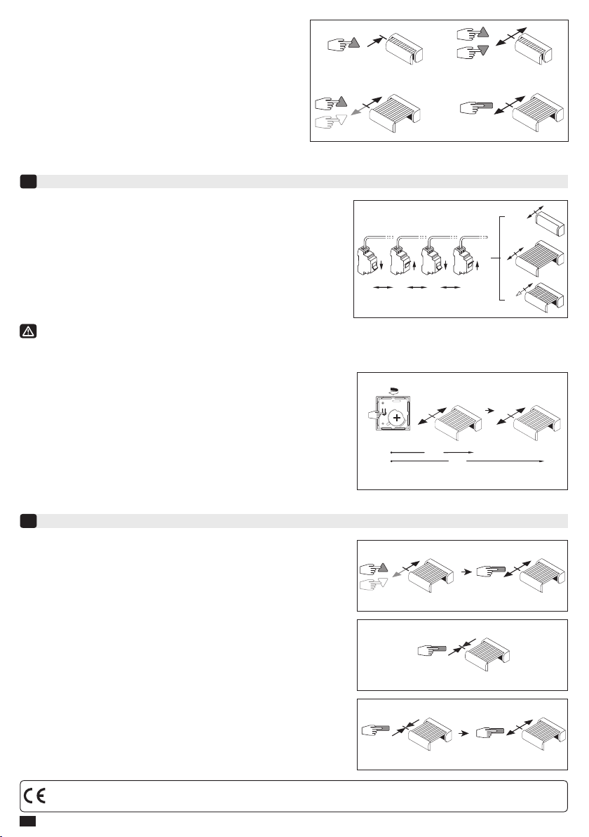
- Couper l’alimentation 12V du moteur pendant 2 secondes.
- Rétablir l’alimentation 12V du moteur pendant 7 secondes.
- Couper l’alimentation 12V du moteur pendant 2 secondes.
- Rétablir l’alimentation du moteur.
Si le moteur se trouve en position de n de course (haute ou basse), il
effectue une brève rotation dans les deux sens. Si le moteur se trouve
dans une autre position, il effectue une rotation de 5 secondes dans un
sens quelconque.
10.2- Ensuite valider l’annulation de la programmation du moteur
concerné depuis l’émetteur de commande individuelle :
- Appuyer plus de 7 secondes sur la touche PROG de l’émetteur. Maintenir
l’appui jusqu’à ce que le moteur effectue une première rotation de 0,5
seconde dans un sens puis dans l’autre, puis quelques secondes plus tard
une seconde rotation de 0,5 seconde dans les deux sens.
L’opération est terminée.
Annulation de la programmation
10
Si vous intervenez sur l’alimentation de plusieurs moteurs, ils seront tous dans ce mode. Il convient donc
« d’éjecter » de ce mode tous les moteurs non concernés par cette modication en appuyant sur une touche de
commande d’un émetteur programmé.
5s.
OFF
2s 7s 2s
ON ONOFF
2s.
7s.
PROG ≥ 7s.
5s.
0,5s.
0,5s. 5s.
1-
2-
3-
Enregistrement / commande / suppression de la position intermédiaire
11
1-
Enregistrement :
- Positionner le moteur sur la position intermédiaire désirée.
- Appuyer 5 secondes sur la touche « Stop ». Le moteur effectue une
rotation de 0,5 seconde dans un sens puis dans l’autre.
2-
Commande :
- Moteur à l’arrêt, appuyer sur la touche « Stop » pendant 0,5 seconde. Le
moteur rejoint la position intermédiaire.
3-
Suppression :
- Appuyer sur la touche stop pendant 0,5 s. Le moteur
rejoint la position intermédiaire.
- Appuyer 5 secondes sur la touche « Stop », le moteur effectue une
rotation de 0,5 seconde dans un sens puis dans l’autre.
La position intermédiaire est supprimée.
La mémoire du moteur est maintenant complètement vidée. Effectuer
de nouveau la programmation complète du moteur.
9.2- Ré-ajustement du n de course haut : (uniquement dans
le cas d’un réglage manuel (store sans butée en fermeture))
1- Positionner le moteur sur le point d’arrêt haut réglé en §2.3 à
l’aide de la touche « Montée ».
2- Appuyer simultanément sur les touches « Montée » et
« Descente » pendant 5 secondes. Le moteur effectue une
rotation de 0,5 seconde dans un sens puis dans l’autre.
3- Afner le réglage à l’aide des touches « Descente » et
« Montée » pour obtenir la position de n de course souhaitée.
4- Appuyer 2 secondes sur la touche « Stop ». Le moteur effectue
une rotation de 0,5 seconde dans un sens puis dans l’autre.
La nouvelle position de n de course est mémorisée.
2s.
5s.
1- 2-
3- 4-
Le moteur est maintenant en mode « annulation de la programmation ».
Par la présente, SIMU SAS, F-70103 GRAY déclare en tant que fabricant que la motorisation couverte par ces instructions et utilisée comme indiqué dans ces
instructions, est conforme aux exigences essentielles des Directives Européennes applicables et en particulier à la Directive Machine 2006/42/EC et à la Directive
Radio 2014/53/EU. Le texte complet de la déclaration de conformité à l’UE est disponible sur www.simu.com. Emmanuel CARMIER, directeur général, GRAY, 07/2017.