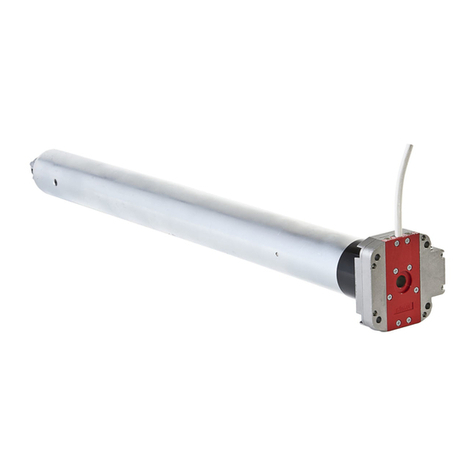
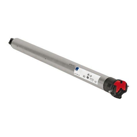
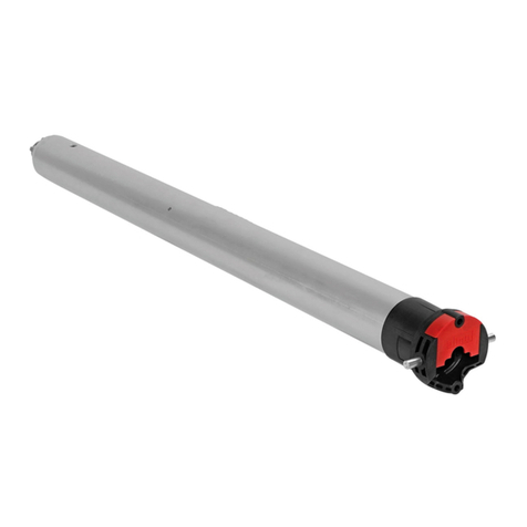
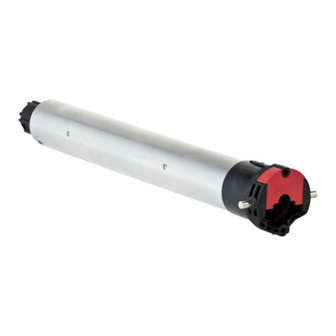
Simu AUTOSUN 2008546 User manual

Présentation
1
F SYSTEME AUTOSUN - 2008546 - 2008547 - 2008548
S.A.S. au capital de 5 000 000 �- Z.I. Les Giranaux - BP71 - 70103 Arc-Les-Gray CEDEX - FRANCE - RCS VESOUL B 425 650 090 - SIRET 425 650 090 00011 - n° T.V.A CEE FR 87 425 650 090
5055194B
Lire attentivement cette
notice avant toute utilisation.
1/4
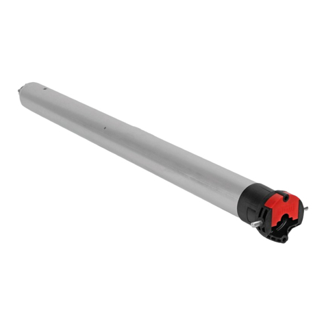
Le système Autosun est un système complet solaire pour la motorisa-
tion de volets roulants rénovation de façade ou de toit. Il est composé de :
1- Moteur 12V T3.5 DC EHz, 3, 6 ou 10 Nm.
2- Panneau solaire 12V.
3- Pack batterie NiMh 12V 2.2Ah.
En option :
4- Alimentation de dépannage réf.: 9014738. Permet d’effectuer une recharge
rapide de la batterie du système Autosun.
1
2
3
4
Emetteurs compatibles
2
Consignes pour l’autonomie du système
3
• Le poids du volet roulant doit respecter les abaques déterminés pour chacun d es
moteurs. Les hauteurs maximum enroulables sont : 1600 mm pour un moteur de 3Nm,
2400 pour un 6Nm et 2700 pour un 10Nm.
• Ces préconisations sont déterminées à partir de données moyennes annuelles et pour
une utilisation du volet roulant à raison de 2 cycles / jour (1 cycle = 1 montée et 1
descente). Attention, 1 cycle maximum pour moteur 10 Nm en cas d’orientation Nord.
Pour les années exceptionnelles, se servir de l’alimentation de dépannage pour rechar-
ger la batterie du système Autosun.
•Le panneau solaire doit toujours ètre positionné sur le coffre du volet roulant de manière
à être exposé le plus possible au rayonnement du soleil.
Rappel : Installation du panneau solaire
4
4.1 - Fixation du panneau par rivetage
Perçage pour panneau situé à gauche du coffre : Perçage pour panneau situé à droite du coffre :
28 10,5
30
Ø16
449
2810,5
30 Ø16
449
- Veillez à ne pas blesser les câbles lors de l’installation. Ebavurer tous les perçages.
- Ne pas apposer sur le panneau solaire de produit pouvant filtrer les rayons du soleil
(ex.: peinture…)
- Maintenir les cellules phovoltaïques propres en les nettoyant à l’eau claire, à l’aide
d’un chiffon doux afin de ne pas les rayer (1fois par mois)
- Par temps neigeux, veillez à ne pas laisser s’accumuler la neige sur le panneau.
- Attention ! Les câbles et les connecteurs doivent être protégés de l’enroulement du
volet roulant.
ORIENTATION EST / OUEST / SUD ORIENTATION NORD
3 Nm
6 Nm
10 Nm
2 cycles /jour
1 cycle /jour maxi.
1 : Emetteur Hz COLOR+ mural
2 : Emetteur Hz COLOR+ mobile 1 / 5 canaux
3 : Emetteur Hz Color Multi 16 canaux / Timer Multi /
Timer Easy
Portée des émetteurs Hz : 20 m à travers 2 murs de
béton armé.
12 émetteurs max. par moteur.
Eloigner les émetteurs de toute surface ou structure
métallique qui pourraient nuire à leur bon fonctionnement
(perte de portée).
Emplacement de la touche PROG sur les
émetteurs Hz :
1 2 3
Ce système autonome a été développé pour fonctionner dans les pays suivants : France, Allemagne, Grande Bretagne, Belgique, Pays Bas,
République Tchèque, Pologne, Irlande, Espagne, Portugal, Italie, Grèce, Suisse, Luxembourg, Danemark, Autriche, Hongrie, Etats-Unis ( hors Alaska),
Turquie, Liban et Australie. Pour toute autre zone, veuillez nous contacter.

2/4
Rappel : Mise en place du pack batterie
5
- Charger la batterie avant utilisation avec le chargeur réf.: 9014738. Attention : ne pas char-
ger au dessus de 70°C.
- Temps de charge max.: 3h 30min. 2 charges par an maximum.
- Ne jamais laisser la batterie déchargée.
- Ne pas ouvrir ou percer le pack batterie. Ne pas jeter la batterie au feu, risque d’explosion. Installer à
1 m minimum de toute source de flamme.
- Ne pas provoquer de court-circuit aux bornes de la batterie, risque de brûlure et d’explosion.
- Le remplacement, par un modèle identique, doit être effectué par un professionnel.
- Ne pas jeter à la poubelle. Produit recyclable à rapporter dans un centre de collecte.
- La batterie doit être abritée de la pluie (IP X4).
- La batterie doit être accessible afin de procéder à une recharge éventuelle (voir notice 5055192)
- Pour plus d’information pour l’intégration de la batterie en fonction du type de coffre consulter le
Cahier Technique réf.: 5057753
- Pour plus d’information pour l’installation du moteur, se référer à la notice réf.: 5055191
- Pour plus d’information pour l’installation des panneaux
se référer à la notice réf.: 5117585
4.2 - Fixation du panneau
1- Passer les fils du panneau à l’intérieur du coffre (trou Ø16) avec la
mousse de protection.
2- Mettre en place le panneau à l’aide de rivets POP aluminium Ø4,8
dans les trous Ø5 percés durant l’opération 4.1.
2
1
18,7 mm Max.
Touche de programmation déportée
Connecteur pour chargeur
1
1
2
Rappel : installation du moteur
6
Ø min.
(mm)
A
(mm) ØB
(mm) C
(mm) D
(mm) L1
(mm) L2
(mm)
A ØB ØB
A
C
D
L2
L1
29
Ø38,2
T3.5 DC EHz
12 Vcc
3Nm - 6Nm - 10Nm 37 433 4,2 8 5,5 457 470
1
23
4
PLASTITE FXS N7\7X12 ZING
1,2
40
9016635
=
batterie 12V - 2.2Ah réf : 9014734 T3.5 DC EHz
a
b
Réglage des fins de course
7
7.1
a- Connecter l’alimentation du moteur.
b- Connecter le panneau solaire au pack batterie.
- Durant les opérations de ce chapitre (§7), ne pas
travailler sur plusieurs moteurs simultanément.
1
1
1
1
2
2
478,5
2
18
10
Ø 3mm

>>
c- Appuyer simultanément sur les touches “montée” et “descente” d’un émetteur Hz. Le moteur effectue une rotation de 0,5
seconde dans un sens puis dans l’autre. Cet émetteur commande maintenant le moteur en mode instable. Passer à l’étape
7.2.
>>
OK >> 7.3
OK >> 7.3
>> >> >>
3s
>>>>
7.2 - Configuration du sens de rotation
Appuyer sur la touche “montée” de l’émetteur :
a- Si l’axe tourne dans le sens “montée”, passer à l’étape 7.3.
b- Si l’axe tourne dans le sens “descente”, inverser le sens de rotation en appuyant sur la
touche “stop” pendant au moins 3 secondes. Le moteur confirme la modification par une
rotation de 0,5 seconde dans un sens puis dans l’autre. Passer à l’étape 7.3.
7.3 -
Réglage des fins de course
- Le réglage des fins de course du moteur T3.5DC EHz
s’effectue de 4 façons différentes en fonction des
paramètres suivants :
-Présence ou absence de butées sur la lame finale, liaison
souple ou rigide* entre l’axe d’enroulement et le tablier.
A
*V.A.R
V.A.S
Easylink
B
*V.A.R
V.A.S
Easylink
C
D
1- Appuyer simultanément sur les touches “montée” et “descente” de l’émetteur Hz, le moteur effectue une
rotation de 0,5 seconde dans un sens puis dans l’autre.
2- Appuyer sur la touche “stop”pendant 2 s. le moteur effectue une rotation de 0,5 s. dans un sens puis dans
l’autre. L’opération est terminée. Passer au §8.
2s
1A2
2s
1B234
1- Positionner le moteur sur le point d’arrêt haut souhaité à l’aide des touches “montée” et “descente”.
2- Appuyer simultanément sur les touches “stop” et “descente” pour mémoriser le point d’arrêt haut. Le moteur se met automatiquement en rotation en descente.
3- Appuyer sur la touche “stop” pour immobiliser le moteur.
4- Appuyer 2 secondes sur la touche “stop” pour valider le réglage, le moteur effectue une rotation de 0,5 seconde dans un sens puis dans l’autre. L’opération est termi-
née. Passer au §8.
2s
C3412
1- Positionner le moteur sur le point d’arrêt bas souhaité à l’aide des touches “descente” et“montée”.
2- Appuyer simultanément sur les touches “stop” et “montée” pour mémoriser le point d’arrêt bas. Le moteur se met automatiquement en rotation en montée.
3- Appuyer sur la touche “stop” pour immobiliser le moteur.
4- Appuyer 2 secondes sur la touche “stop” pour valider le réglage, le moteur effectue une rotation de 0,5 seconde dans un sens puis dans l’autre. L’opération est termi-
née. Passer au §8.
2s
1D23 654
1- Positionner le moteur sur le point d’arrêt bas souhaité à l’aide des touches “descente” et“montée”.
2- Appuyer simultanément sur les touches “stop” et “montée” pour mémoriser le point d’arrêt bas. Le moteur se met automatiquement en rotation en montée.
3- Lorsque le moteur arrive au point d’arrêt haut souhaité, appuyer sur la touche “stop”.
4- Si nécessaire, affiner le réglage a l’aide des touches “descente” et“montée”.
5- Appuyer sur les touches “stop” et “descente” pour mémoriser le point d’arrêt haut. Le moteur se met automatiquement en rotation en descente.
6- Appuyer 2 secondes sur la touche “stop” pour valider les réglages fin de course. Le moteur s’arrête puis effectue une rotation de 0,5 seconde dans un sens puis dans
l’autre. L’opération est terminée. Passer au §8.
- Après ces opérations vous pouvez programmer l’émetteur utilisé précédemment comme premier point de commande. Dans ce cas, passez au
chapitre §8. Dans le cas contraire, pour programmer un autre émetteur comme premier point de commande : Appuyer 3 s. sur le bouton de
programmation déporté situé dans le pack batterie (§5). Le moteur effectue une courte rotation dans un sens puis dans l’autre, et avant 2
min., effectuer l’opération 8 pour valider la programmation.
3/4
Programmation du premier point de commande individuelle
8
PROG ≤1s
- Appuyer environ 1 seconde sur la touche “PROG” de l’émetteur. le moteur effectue une rotation de 0,5 seconde dans
un sens puis dans l’autre. Votre émetteur est maintenant programmé et commande le moteur en mode stable.
Toutes les fonctions décrites §11 sont actives.
Programmation d’un nouveau point de commande (individuelle, groupe ou générale)
9
PROG 3s
3s
9.1 - Ouvrir la mémoire du moteur depuis l’émetteur de commande individuelle :
- Appuyer environ 3 secondes sur la touche “PROG”de l’émetteur de commande individuelle
(ou du pack batterie). le moteur effectue une rotation de 0,5 seconde dans un sens puis
dans l’autre.

PROG
1s
9.2 - Valider l’opération depuis le nouvel émetteur à programmer :
- Appuyer environ 1 seconde sur la touche “PROG” du nouvel émetteur. Le moteur effectue une rotation de 0,5
seconde dans un sens puis dans l’autre.
- Si votre nouveau point de commande est une commande de groupe : répéter les opérations 9.1 et 9.2 pour chaque moteur du groupe.
- Si votre nouveau point de commande est une commande générale : répéter les opérations 9.1 et 9.2 pour chaque moteur de l’installation.
- Pour supprimer un émetteur de la mémoire du moteur : Effectuer les opérations 9.1 depuis l’émetteur de commande individuelle et l’opération 9.2 depuis l’émetteur à supprimer.
Enregistrement :
- Positionner le moteur sur la position intermédiaire
désirée.
- Appuyer 5s sur la touche “stop”. Le moteur effectue
une rotation de 0,5 s dans un sens puis dans l’autre.
Commande :
- Appuyer sur la touche “stop” pendant 0,5s.
Le moteur rejoint la position intermédiaire.
Enregistrement / commande / suppression de la position intermédiaire
10
0,5s
5s
Désactivation :
- Appuyer 1 seconde max. sur la touche
“PROG” du pack batterie. Le moteur effec-
tue une courte rotation dans un sens puis
une seconde plus tard dans l’autre sens
Activation :
- Appuyer 1 seconde max. sur la touche
“PROG” du pack batterie. le moteur
effectue une rotation de 0,5 seconde
dans un sens puis dans l’autre.
Activation / désactivation radio
12
1s
1s
1
s
Fonctionnement du moteur T3.5 DC EHz
11
11.1 - Avec une batterie en bon état de charge, les commandes possibles sont : Montée, stop et descente. Il est également possible de commander une position
intermédiaire (voir §10).
11.2 - Fonction détection du gel : Un blocage du volet en présence de gel à la montée provoque l’arrêt du moteur.
11.3 - Fonction détection d’obstacle : Un blocage du volet en présence d’un obstacle à la descente provoque l’arrêt du moteur, puis une inversion du mouve-
ment.
11.4 - Fonction protection de la batterie contre la décharge excessive : Avant chaque opération de montée ou de descente, le moteur contrôle la tension
de la batterie.
Si la tension est inférieure à 11,5V : Le moteur marquera un temps d’arrêt au début de chaque ordre de montée. La descente n’est possible qu’en donnant plu-
sieurs inpulsions sur la touche “descente”.
Si la tension est inférieure à 10V : Le moteur n’acceptera aucun ordre de commande.
Dans les deux cas, utiliser le chargeur de dépannage afin d’effectuer une recharge rapide de la batterie. Le fonctionnnement du moteur redevien-
dra normal uniquement si la tension de la batterie remonte au dessus de 12V.
4/4
Ré-ajustement des positions de fins de course
13
Effacement de tous les émetteurs programmés
14
Annulation complète de la programmation
15
- Appuyer plus de 12 secondes sur la touche “PROG” du pack batterie. Le moteur effectue à trois
reprises une courte rotation dans un sens puis dans l’autre. L’opération est terminée.
Le moteur se retrouve dans sa configuration d’origine, plus aucun émetteur n’est programmé
en mémoire. Reprendre la programmation complète du moteur (sens de rotation, fins de
course et points de commande.)
13.1 : Ré-ajustement des positions de fins de course haut (montages B et D uniquement)
1- Positionner le moteur sur le point d’arrêt haut réglé en §7.3 à l’aide de la touche “montée”.
2- Appuyer simultanément sur les touches “montée” et “descente” pendant 5 secondes. Le moteur effec-
tue une rotation de 0,5 seconde dans un sens puis dans l’autre.
3- Affiner le réglage à l’aide des touches “descente” et “montée” pour obtenir la position de fin de course
souhaitée.
4- Appuyer 2 secondes sur la touche “stop”. Le moteur effectue une rotation de 0,5 seconde dans un sens
puis dans l’autre, la nouvelle position de fin de course est mémorisée.
5s
3
21 4
2s
13.2 : Ré-ajustement des positions de fins de course bas (montages C et D uniquement)
1- Positionner le moteur sur le point d’arrêt bas réglé en §7.3 à l’aide de la touche “descente”.
2- Appuyer simultanément sur les touches “montée” et “descente” pendant 5 secondes. Le moteur effec-
tue une rotation de 0,5 seconde dans un sens puis dans l’autre.
3- Affiner le réglage à l’aide des touches “descente” et “montée” pour obtenir la position de fin de course
souhaitée.
4- Appuyer 2 secondes sur la touche “stop”. Le moteur effectue une rotation de 0,5 seconde dans un sens
puis dans l’autre, la nouvelle position de fin de course est mémorisée.
3412
5s
2s
12s
2s 7s 12s
- Appuyer plus de 7 secondes sur la touche “PROG” du pack batterie. le moteur effectue à deux reprises une rota-
tion de 0,5 seconde dans un sens puis dans l’autre. L’opération est terminée.
Le moteur ne dispose plus d’aucun émetteur programmé en mémoire, mais les réglages du sens de rota-
tion et des fins de course sont conservés. Reprendre l’opération 7.1c puis l’opération 8 pour programmer
une nouvelle commande individuelle.
7s
2s 5s
- Il est possible de désactiver la radio afin de de pas vider prématurément la batterie pendant les périodes où le panneau solaire n’est pas en mesure de
fonctionner normalement (emballage du volet roulant, transport, stockage…). Aprés la pose du volet roulant, il suffira d’activer la radio pour obtenir un
fonctionnement normal.
- Le ré-ajustement est automatique tous les 56 cycles (pendant 3 cycles) dans les cas suivants : Fin de course Haut, montages A et C, Fin de
course bas, montages A et B.
Suppression : Positionner le moteur sur la position intermédiaire. Appuyer 5s sur la touche stop. la position intermédiaire est supprimée.

Presentation
1
GB AUTOSUN SYSTEM - 2008546 - 2008547 - 2008548
5055194B
Read carefully these instruc-
tions before any use.
1/4
The Autosun system is a complete solar powered motor system for
roller shutters in walls and roofs. It comprises:
1- 12V T3.5 DC EHz Motor, 3, 6 or 10 Nm.
2- 12V solar panel
3- NiMh 12V 2.2Ah battery pack.
As options :
4- Emergency power supply ref: 9014738. Allows rapid recharging of the battery for
the Autosun system.
1
2
3
4
1 : COLOR+ Wall Hz transmitter
2 : COLOR+ 1/5 channels Hz transmitter
3 : Color Multi 16 / Timer Easy / Timer Multi
transmitters
Transmitters range :
- 1, 2 and 3 : 20 m through 2 concrete walls .
- Do not position the transmitter near metal in order to avoid range losses.
Location of the “PROG” key on Hz
transmitters:
Compatible transmitters
2
Consign concerning the autonomy of the system
3
• The weight of roller shutter must comply with the charts determined for the motors.
Maximum shutter heights are: 1600 mm for 3Nm motors, 2400 mm for 6Nm motors
and 2700 mm for 10Nm motors.
• These consign are based on average annual data and for a roller shutter used for 2
cycles/day (1 cycle = 1 up and 1 down movement). Attention 1 cycle maximum for the
10 Nm motor in case of north orientation (or South orientation for Australia only).
In exceptional years, use the backup power supply to recharge the Autosun’s battery.
• The solar panel should always be placed on the shutter housing so as to be as exposed
as possible to the sun’s rays.
Reminder : Solar panel installation
4
ORIENTATION EAST / WEST / SOUTH ORIENTATION NORTH
3 Nm
6 Nm
10 Nm
2 cycles/day
1 cycle/day max.
+ Australia (orientation E/W/N) + Australia (orientation S)
4.1 - Fastening the solar Panel by riveting
Drilling measurements (mm) for panels placed to the left of the box: Drilling measurements (mm) for panel placed to the right of the box:
28 10,5
30
Ø16
449
2810,5
30 Ø16
449
- Ensure that the cables are not damaged during installation. Smooth the edges of all
the drilled holes.
- Do not put anything on the solar panel that would lter the sun’s ray (e.g.: paint…).
- Keep the photovoltaic cells clean by cleaning them with clean water, using a soft cloth
to avoid scratching them (once a month).
- In winter, do not allow snow to build up on the panels.
- Caution! The cables and connectors must be protected from the roller shutter
movement.
1 2 3
This system was developped to run into the following countries: France, Germany, England, Belgium, Netherlands, Czech Republic, Poland, Ireland, Spain, Portugal,
Italy, Greece, Luxembourg, Denmark, Austria, Switzerland, Hungary, USA (excluding Alaska), Turkey, Lebanon and Australia. For others countries, please contact us.
S.A.S. au capital de 5 000 000 - Z.I. Les Giranaux - BP71 - 70103 Arc-Les-Gray CEDEX - FRANCE - RCS VESOUL B 425 650 090 - SIRET 425 650 090 00011 - n° T.V.A CEE FR 87 425 650 090

2/4
Reminder: Battery pack installation
5
- Recharge the battery before use with the charger ref.: 9014738. WARNING: Do not charge
at a temperature above 70°C.
- Charge duration: 3h30 max. 2 charges by year max.
- Never leave a battery in a discharged condition.
- No not open or pierce the battery.
- Do not put the battery into a fire, risk of explosion. Keep away (1m minimum) from from all types of
flames, sparks or incandescent material.
- Do not create a short circuit on the battery terminals: danger of burns and explosion.
- The battery must be replaced by a professional with an identical model.
- Do not put in the dustbin, this is a recyclable product.
- The battery must be sheltered from the rain (IP X4).
-
The battery must be accessible in order to carry out possible recharging (see instruction sheet 5055192).
- For more information about installation of the battery depending on the type of case, see Technical
booklet ref: 5059076
- For more information about installation of the motor, see technical leaflet ref: 5055191.
- For more information about installation of the panel, see
technical leaflet ref: 5117585.
4.2 - Fixing the Panel
1- Pass the wires of the Panel inside the box (Ø16 hole) with the
protective foam.
2- Fix the Panel using aluminium Ø4,8 pop rivets in the Ø5 holes dril-
led during operation 4.1.
2
1
18,7 mm Max.
Programming button
Connector for charger
1
1
2
Reminder: motor installation
6
Ø min.
(mm)
A
(mm) ØB
(mm) C
(mm) D
(mm) L1
(mm) L2
(mm)
A ØB ØB
A
C
D
L2
L1
29
Ø38,2
T3.5 DC EHz
12 Vcc
3Nm - 6Nm - 10Nm 37 433 4,2 8 5,5 457 470
1
23
4
PLASTITE FXS N7\7X12 ZING
1,2
40
9016635
=
battery 12V - 2.2Ah ref.: 9014734 T3.5 DC EHz
a
b
End limits adjustment
7
7.1
a- Connect the motor to the power supply.
b- Connect the solar panel to the battery pack.
- During the operations in this section (§7), do not
work on several motors at the same time.
1
1
1
1
2
2
478,5
2
18
10
Ø 3mm

>>
c- Press simultaneously on the UP and DOWN buttons of a Hz transmitter. The motor turns 0.5 second in one direction, then in the
other.
This transmitter now commands the motor in unstable mode. Go to step §7.2
>>
OK >> 7.3
OK >> 7.3
>> >> >>
3s
>>>>
7.2 -Test and setting the direction of rotation
Press on the UP button on the transmitter :
a- If the shaft turns in the UP direction, go to step §7.3.
b- If the motorized tube runs in the DOWN direction, reverse the rotation direction by pressing
the STOP key for at least 3 seconds. The motor will confirm the reversal of the rotation direc-
tion by running 0.5 second in both directions. Go to step §7.3.
7.3 -
End limits adjustment
- The end limits of the T3.5DC EHz are adjusted
in 4 different ways depending on the following
conditions:
- Bottom slat stop or not, stiff* or flexible link between
the rolling shaft and the shutter.
A
*V.A.R
V.A.S
Easylink
B
*V.A.R
V.A.S
Easylink
C
D
1- Simultaneously press the UP and DOWN keys of a Hz transmitter. The motor will run for 0.5 second in one
direction and then in the other.
2- Press the “stop” key for 2 s. The motor will run for 0.5 second in one direction and then in the other. The
operation is completed. Go to step §8.
2s
1A2
2s
1B234
1- Position the motor on the UP end limit by using the keys UP or DOWN.
2- To memorize the UP end limit position, press simultaneoulsy the keys STOP and DOWN. The motor will run automatically in the DOWN direction.
3- Press the STOP key to immobilize the motor.
4- Press 2 seconds the STOP key to validate the setting. The motor will run for half a second in one direction, then in the other direction. The operation is comple-
ted. Go to step §8.
2s
C3412
1- Position the motor on the DOWN end limit by using the keys UP or DOWN.
2- To memorize the DOWN end limit position, press simultaneoulsy the keys STOP and UP. The motor will run automatically in the UP direction.
3- Press the STOP key to immobilize the motor.
4- Press 2 seconds the STOP key to validate the setting. The motor will run for 0.5 second in one direction, then in the other. The operation is completed. Go to
step §8.
2s
1D23 654
1- Position the motor on the DOWN end limit by using the keys DOWN or UP.
2- To memorize the DOWN end limit position, press simultaneoulsy the keys STOP and UP. The motor will run automatically in the UP direction.
3- When the motor arrives on the UP End limit, press the key STOP.
4- If necessary adjust the position with the keys UP or DOWN.
5- To memorize the UP end limit position, press simultaneoulsy the keys STOP and DOWN. The motor will run automatically in the DOWN direction.
6- Press 2 seconds the STOP key to validate the setting. The motor will stop, and will run for 0.5 second in one direction, then in the other. The operation is com-
pleted. Go to step §8
- After these operations you can programme the transmitter used previously as the first point of control, in which case refer to chapter §8.
Conversely, to programme another transmitter as the first point of control: Press for 3 sec on the remote programming button located on the
battery pack (§5). The motor rotates briefly in one direction and then the other, then within 2 minutes perform operation 8 to confirm the
programming.
3/4
Programming the first individual control point
8
PROG ≤1s
- Press the transmitter “PROG” Key for approximately one second. The motor will run for 0.5 second in one direction and
then in the other. Your transmitter is now programmed to control the motor in stable mode. All the functions
described in §11 are active.
Programming a new (individual, group or main) control point
9
PROG
3s
3s
9.1 - Open the memory of the motor from the control transmitter:
- Press the “PROG” key of the transmitter (or of the battery pack) for about 3 seconds. The
motor will run for 0.5 second in one direction and then in the other.

PROG 1s
9.2 - Validate the operation from the new transmitter you want to programm:
- Press the “PROG” key of the transmitter for about 1 second. The motor will run for 0.5 second in one direction
and then in the other.
- For group controls, repeat operations 9.1 and 9.2 for each motor in the group.
- For main controls, repeat operations 9.1 and 9.2 for each motor in the installation.
- To delete an transmitter from the memory of a motor, perform operations 9.1 with a programmed transmitter, then perform the operation 9.2 with the transmitter to be deleted.
Recording:
- Position the motor on the wanted position.
- Press 5 seconds on the “stop” key. The motor
will run for 0.5 second in one direction and
then in the other.
Controling:
- Press on the “stop” key for 0.5 s. the
motor goes to the intermediate posi-
tion.
Recording / controling / deleting intermediate position
10
0,5s
5s
Deactivation :
- Press the “PROG” key of the battery pack
for 1 second max. The motor rotates brie-
fly in one direction and then 1 second later
in the other direction.
Activation :
- Press the “PROG” key of the battery
pack for 1 second max. The motor will
run for 0.5 second in one direction and
then in the other.
Radio activation / deactivation
12
1s
1s
1
s
T3.5 DC EHz motor functions
11
11.1 - With a well charged battery, the possible commands are: Up, stop and down. It is also possible to set an intermediate position (see §10).
11.2 - Frost detection function: The motor stops if the shutter is jammed by ice during opening.
11.3 - Detection of obstructions function: Jamming of the shutter due to the presence of an obstruction when closing the shutter causes the motor to stop
and then run in the reverse direction.
11.4 - Battery protection against excessive discharge: Before each lifting or lowering of the shutter, the motor checks the voltage of the battery.
If the voltage is below 11.5V: The motor will pause at the beginning of each command to lift the shutter. The shutter can only be closed by pressing several times
on the «down» button.
If the voltage is below 10V: The receiver won’t accept any commands.
In these two cases, use the emergency charger in order to perform a quick battery recharge. Operation of the motor will return to normal only if
the battery voltage goes above 12V.
4/4
Re-adjustement of end limits
13
Cancelling all the programmed transmitters
14
Cancelling programming
15
- Press the “PROG” key of the battery pack more than 12 seconds. The motor will run 3 times in one
direction and then in the other. The operation is completed.
The motor returns to its original set up, with no transmitter programmed in the memory.
Redo the complete programming procedure for the motor (direction of rotation, end limits
and control points).
13.1 - Re-adjustement of UP end limits (assemblies B and D only)
1- Position the motor on the UP end limit previously set in §7.3 with the UP key.
2- Press simultaneously for 5 seconds the UP and DOWN keys, The motor will run for 0.5 second in one
direction and then in the other direction.
3- Adjust the new position with the UP and DOWN keys.
4- Validate the new position by pressing 2 seconds the STOP key. The motor will run for 0.5 second in one
direction and then in the other. The new end limits setting is memorized.
5s
3
21 4
2s
13.2 - Re-adjustement of DOWN end limits (assemblies C and D only)
1- Position the motor on the DOWN end limit previously set in §7.3 with the DOWN key.
2- Press simultaneously for 5 secondes the UP and DOWN keys, The motor will run for 0.5 second in one
direction and then in the other direction.
3- Adjust the new position with the UP and DOWN keys.
4- Validate the new position by pressing 2 seconds the STOP key. The motor will run for 0.5 second in one
direction and then in the other. The new end limits setting is memorized.
3412
5s
2s
12s
2s 7s 12s
- It is possible to deactivate the radio function so as not to prematurely drain the battery during periods when the solar panel is not able to
operate normally (packaging of the roller shutter, transport, storage...). After installation of the roller shutter, normal operation will be res-
tored by reactivating the radio function.
- The re-adjustment of end limits is automatic every 56 cycles (during 3 cycles) for the following installation : Up end limit, mounting A and C,
Down end limit, mounting A and B.
- Press the “PROG” key of the battery pack more than 7 seconds. The motor will run 2 times for in one direction and
then in the other. The operation is completed.
The motor doesn’t have any transmitter programmed in its memory any more, but the settings for the
direction of rotation and end limits are retained. Perform operation 7.1c then operation 8 to programm
a new individual control.
7s
2s 5s
Deleting : Position the motor on the intermediate position. Press 5 seconds on the Stop key, the intermediate position is deleted.

Beschreibung
1
D SYSTEM AUTOSUN - 2008546 - 2008547 - 2008548
S.A.S. au capital de 5 000 000 �- Z.I. Les Giranaux - BP71 - 70103 Arc-Les-Gray CEDEX - FRANCE - RCS VESOUL B 425 650 090 - SIRET 425 650 090 00011 - n° T.V.A CEE FR 87 425 650 090
5055194B
Bitte gründlich vor der
Anwendung lesen.
1/4
Das System Autosun ist ein komplettes Solarsystem für die
Motorisierung von Rolläden, an Fassaden oder auf dem Dach. Es besteht aus:
1- Motor 12V T3.5 DC EHz, 3, 6 oder 10 Nm.
2- Solarpanel 12V.
3- Batterie Paket NiMh 12V 2.2Ah.
Optional:
4- Ladegerät Art.-Nr.: 9014738. Für eine schnelle Nachladung der Batterie des
Autosun-Systems.
1
2
3
4
1 : Hz Wandsender COLOR+
2 : Hz 1 und 5 Kanal-Sender COLOR+
3 : Color Multi / Timer Easy / Timer Multi
Senderreichweiten:
- 1, 2 und 3 : 20m durch 2 Stahlbetonwände.
- Bewahren Sie den Sender nicht in der Nähe metallischer Objekte auf; diese könn-
ten die Senderleistung beeinflussen (geringere Reichweite).
Anordnung der “Prog” Taste am
Hz-Sender:
Kompatible Sender
2
Anweisung für die Autonomiefunktion des Systems
3
• Das Rollladengewicht muss mit dem für jeden der Motoren festgelegten Diagrammen
übereinstimmen. Die aufrollbaren Maximalhöhen sind: 1600 mm für einen 3Nm, 2400
für einen 6Nm- und 2700 für einen 10Nm-Motor.
• Die Anweisung der Tabellen werden ausgehend von jährlichen Mittelwerten ermittelt
und gehen von einer Rollladenbenutzung à 2 Zyklen/Tag aus (1 Zyklus = 1 x Hochfahren
und 1 x Herunterfahren).
Achtung: Bei einer Ausrichtung nach Norden (oder nach Süden in Australien) ist für den Motor mit
10Nm maximal 1 Zyklus pro Tag vorgesehen.
• In Ausnahmejahren kann das Ladegerät zum Aufladen der Systembatterie(n) dienen.
Das Solarpanel muss immer so installiert werden, dass die Sonnenstrahlen es erreichen.
Hinweis: Installation des Solarpanel
4
ORIENTIERUNG: OST / WEST / SÜD ORIENTERUNG: NORD
3 Nm
6 Nm
10 Nm
1 Zyklus / Tag max.
2 Zyklen / Tag max.
4.1 - Panelbefestigung durch Vernietung
Bohrung wenn Panel linksseitig: Bohrung wenn Panel rechtsseitig:
28 10,5
30
Ø16
449
2810,5
30 Ø16
449
- Beachten Sie bei der Installation, dass Sie die Kabel nicht beschädigen. Alle Bohrungen entgraten.
- Auf das Solarzellenpanel keine Mittel aufbringen, die in der Lage sind, die Sonnenstrahlen zu fil-
trieren (z.B: Lack…).
- Reinigen Sie die Photovoltaikzellen mit klarem Wasser und einem weichen Lappen, um sie nicht zu
verkratzen (einmal pro Monat).
- Bei Schneewetter, beachten dass sich kein Schnee auf dem Paneel ansammelt.
- Achtung! Die Kabel und Steckverbinder müssen davor geschützt werden, vom Rollladen mit
aufgewickelt zu werden
1 2 3
Dieses System ist für die Verwendung in folgenden Ländern entwickelt worden: Frankreich, Deutschland, Belgien, Niederlande, Tschechien, Polen, Grossbritanien, Spanien,
Portugal, Italien, Griechenland,Schweiz, Luxemburg, Dänemark, Österreich, Ungarn, USA (ausgenommen Alaska), Türkei, Libanon, Australien. Für andere Länder setzen Sie sich
bitte mit uns in Verbindung.

2/4
Hinweis: Einbau des Batteriepakets
5
- Laden Sie die Batterie mit dem Ladegerät (Art.-Nr. 9014738) vor dem Gebrauch auf. Achtung :
Laden Sie nicht bei über 70°C auf.
- Max. Ladezeit: 3 Stunden 30 min. 2 maximale Laden pro Jahr.
- Lassen Sie eine Batterie niemals entladen.
- Öffnen Sie die Batterie nicht und machen Sie kein Loch in die Batterie.
- Werfen Sie die Batterie nicht ins Feuer : Explosionsgefahr. Mindestabstand zu einer Flammenquelle: 1 m
- Verursachen Sie keinen Kurzschluss an den Batteriepolen: Verbrennungs- und Explosionsgefahr
- Ist ein Austausch notwendig, muss er von einem Profi gegen ein identisches Modell vorgenommen werden.
- Werfen Sie die Batterie nicht in den Hausmüll, es ist recycelbar.
- Die Batterie muss vom Regen geschützt sein (IP X4).
- Die Batterie muss für eine eventuelle Nachladung gut zugänglich sein (siehe Anwendung Nr. 5055192)
- Für weitere Informationen über den Einbau der Batterie nach Kastenart, siehe Technisches Handbuch Nr.:
5059076
- Für weitere Informationen über den Einbau der Motor, siehe Anleitung Nr.: 5055191
- Für weitere Informationen über die Montage der Panels,
siehe Anleitung Nr. 5117585
4.2 - Panelbefestigung
1- Die Panelkabel mit dem Schutzschaumstoff in den
Kasteninnenraum (Bohrung Ø16) einführen.
2- Panel mit Hilfe von POP Aluminiumniet Ø4,8 in die während dem
Vorgang 4.1 gebohrten Bohrungen Ø5 einsetzen.
2
1
18,7 mm Max.
Programierungstaste
Steckverbinder für das Ladegerät
1
1
2
Hinweis: Motorinstallation
6
Ø min.
(mm)
A
(mm) ØB
(mm) C
(mm) D
(mm) L1
(mm) L2
(mm)
A ØB ØB
A
C
D
L2
L1
29
Ø38,2
T3.5 DC EHz
12 Vcc
3Nm - 6Nm - 10Nm 37 433 4,2 8 5,5 457 470
1
23
4
PLASTITE FXS N7\7X12 ZING
1,2
40
9016635
=
Akku 12V - 2.2Ah réf : 9014734 T3.5 DC EHz
a
b
Einstellung Endbegrenzung
7
7.1
a- Verbinden Sie den Motor mit dem Batteriepaket.
b- Solarpanel an das Batteriepaket anschließen.
- Immer nur einen Motor in Empfangsbereitschaft setzen
1
1
1
1
2
2
478,5
2
18
10
Ø 3mm

>>
c- Drücken Sie gleichzeitig die AUF- und AB-Taste eines Hz Senders. Der Motor läuft 0,5 Sekunde in die eine, dann in die andere
Richtung. Der Sender steuert nun den Motor im Totmannbetrieb. Siehe Schritt 7.2.
>>
OK >> 7.3
OK >> 7.3
>> >> >>
3s
>>>>
7.2 - Überprüfen der Laufrichtung
Drücken Sie die AUF-Taste am Sender:
a- Wenn sich das Rolladenelement nach oben bewegt, wechseln Sie zum Schritt 7.3.
b- Wenn sich das Rolladenelement nach unten bewegt, ändern Sie die Richtung, indem
Sie die STOP-Taste mindestens 3 S. lang gedrückt halten. Der Empfänger bestätigt den
Richtungswechsel und dreht 0,5 S. lang in die eine, dann in die andere Richtung. Weiter mit
Schritt 7.3.
7.3 -
Einstellung der Endbegrenzung
- Die Art der Einstellung der Endbegrenzung hängt von
den vier folgenden Montagesituationen ab:
- Mit oder ohne Endstopper, feste Wellenverbinder* (V.A.R
oder V.A.S) oder flexible Aufhängefedern für den Behang.
A
*V.A.R
V.A.S
Easylink
B
*V.A.R
V.A.S
Easylink
C
D
1- Drücken Sie gleichzeitig die AUF und die AB Taste des Senders. Der Motor läuft für 0,5 Sekunde in die eine
und in die andere Richtung.
2- Drücken Sie die STOP Taste für 2 Sekunden. Der Motor läuft für 0,5 Sekunde in die eine und in die andere
Richtung. Die Einstellung ist beendet. Weiter mit Schritt §8.
2s
1A2
2s
1B234
1- Fahren Sie den Motor mit den AUF und AB Tasten in die obere Endposition.
2- Um die obere Endlage zu speichern , drücken Sie die STOP und die AB Taste gleichzeitig. Der Motor fährt jetzt in AB Richtung.
3- Drücken Sie jetzt die STOP Taste um den Motor anzuhalten.
4- Zur Speicherung der Endbegrenzung OBEN drücken Sie 2 Sekunden lang die STOP Taste. Der Motor läuft 0,5 Sekunde in die eine, dann in die andere Richtung.
Weiter mit Schritt §8.
2s
C3412
1- Fahren Sie den Motor mit den AUF und AB Tasten in die untere Endposition.
2- Um die untere Endlage zu speichern , drücken Sie die STOP und die AUF Taste gleichzeitig. Der Motor fährt jetzt in AUF Richtung.
3- Drücken Sie jetzt die STOP Taste um den Motor anzuhalten.
4- Zur Speicherung der Endbegrenzung OBEN drücken Sie 2 Sekunden lang die STOP Taste. Der Motor läuft 0,5 Sekunde in die eine, dann in die andere Richtung.
Weiter mit Schritt §8.
2s
1D23 654
1- Positionieren Sie den Motor mit den AUF- oder AB Tasten an der Endbegrenzung UNTEN.
2- Zur Speicherung der Endbegrenzung UNTEN drücken Sie gleichzeitig die Tasten STOP und AUF. Der Motor läuft automatisch aufwärts
3- Wenn der Motor das Endbegrenzung OBEN erreicht, drücken Sie die Taste STOP.
4- Justieren Sie die Position gegebenenfalls mit den AUF- oder AB Tasten.
5- Zur Speicherung der Endbegrenzung OBEN drücken Sie gleichzeitig die Tasten STOP & NACH UNTEN. Der Motor läuft automatisch abwärts.
6- Halten Sie die Taste STOP 2 Sekunden lang gedrückt, um die Einstellung zu bestätigen. Der Motor stoppt und läuft 0,5 Sekunde in die eine, dann in die andere
Richtung. Weiter mit Schritt §8.
- Nach diesen Einstellungen, können sie den vorangehend benutzten Empfänger als ersten Steuerpunkt programmieren. In diesem Fall,
gemäß Kapitel §8 vorgehen. Ansonsten, um einen anderen Sender als erster Steuerpunkt zu programmieren: 3 Sek. lang auf den versetzten
Programmierknopf im Batteriepaket drücken (§5). Der Motor dreht kurz in eine Richtung und in die andere. Innerhalb von 2 Min., mit dem
gewünschten Sender §8 durchführen um die Programmierung zu bestätigen.
3/4
Programmierung des ersten individuellen Steuerpunkts
8
PROG ≤1s
- Halten Sie die Taste “PROG” ca. 1 Sekunde lang gedrückt. Der Motor läuft 0,5 Sekunde in die eine, dann in die
andere Richtung.
Ihr Sender ist nun so programmiert, dass er den Motor zuverlässig steuert.Es sind alle in §11 beschriebenen
Funktionen aktiv.
Programmierung eines neuen (individuellen, Gruppen- oder Haupt-) Steuerpunkts
9
PROG 3s
3s
9.1 - Vorbereitung des Motors für einen weiteren Sender:
- Etwa 3 Sekunden lang auf Taste “PROG” des einzelnen Steuersenders (oder des
Batteriepakets) drücken. Der Motor läuft 0,5 Sekunde in die eine, dann in die andere
Richtung.

PROG 1s
9.2 - Bestätigen Sie die Eingaben an dem neu zu programmierenden Sender:
- Halten Sie die Taste “PROG” des Senders ca. 1 Sekunde lang gedrückt. Der Motor läuft 0,5 Sekunde in die eine,
dann in die andere Richtung.
- Für Gruppensteuerungen wiederholen Sie die Schritte 9.1 und 9.2 für jeden Motor der Gruppe.
- Für die Hauptsteuerung wiederholen Sie die Schritte 9.1 und 9.2 für jeden Motor der Installation.
- Um einen Sender aus dem Speicher des Motors zu löschen, wiederholen Sie Schritt 9.1 mit einem programmierten Sender und dann Schritt 9.2 mit dem zu löschenden Sender.
Speichern:
- Fahren Sie den Motor in die gewünschte Position.
- Halten Sie 5 Sekunden die STOP Taste gedrückt. Der
Motor fährt 0,5 Sekunde in die eine, dann in die
andere Richtung.
Kontrolle:
- Halten Sie 0,5 Sekunde die STOP Taste
gedrückt. Der Motor fährt an die gespei-
cherte Zwischenposition.
Speichern / Kontrolle und Löschen
der Zwischenpositionen
10
0,5s
5s
Deaktivierung:
- Etwa 1 Sekunde lang auf Taste “PROG”
des Batteriepakets drücken. Der Motor
dreht kurz in eine Richtung, und eine
Sekunde später, in die andere.
Aktivierung
- Drücken Sie 1 Sekunde lang max. auf
die Taste “PROG” des Batteriepakets.
Der Motor läuft 0,5 Sekunde in die eine,
dann in die andere Richtung.
Aktivierung / Deaktivierung Funkgerät
12
1s
1s
1
s
Betriebsweise vom Motor T3.5 DC EHz
11
11.1 - Bei einer ordentlich geladenen Batterie, sind die möglichen Befehle: aufwärts, Halt und abwärts. Es kann auch eine Zwischenstellung angesteuert werden
(siehe §10).
11.2 - Funktion Frosterfassung: Eine Sperrung des Rolladens wegen Frost führt zum Motorstillstand.
11.3 - Funktion Hinderniserfassung: Eine Sperrung des Rolladens wegen Vorhandensein eines Hindernisses in der Abwärtsbewegung führt zum Motorstillstand,
und dann zu einer Bewegungsumkehr.
11.4 - Funktion Batterieschutz gegen eine zu starke Entladung: Vor jeder Aufwärts- oder Abwärtsbewegung, führt der Motor eine Spannungskontrolle der
Batterie durch.
Bei einer Spannung unter 11,5V: hält der Motor bei Beginn jedes Aufwärtsbefehls kurz an. Die Abwärtsbewegung ist nur durch mehrere Impulse auf die Taste
«Abwärts» möglich.
Bei einer Spannung unter 10V: Nimmt der Empfänger keinen Steuerbefehl an.
In beiden Fällen, das Ladegerät benutzen, um eine schnelle Batterienachladung durchzuführen. Der Motorbetrieb wird erst wieder normal, nach-
dem die Batteriespannung über 12V gestiegen ist.
4/4
Neueinstellung der Endbegrenzung
13
Löschen aller programmierten Sender
14
Löschen der Programmierung
15
- Etwa 12 Sekunde lang auf Taste “PROG” des Batteriepakets drücken. Der Motor führt drei Mal eine
kurze Drehung in eine Richtung und dann in die andere aus.
Der Vorgang ist beendet.
Der Motor hat seine ursprüngliche Konfiguration eingenommen, es ist kein Sender mehr
im Speicher programmiert. Komplette Motorprogrammierung wiederholen (Drehrichtung,
Endschalter und Steuerpunkte)
13.1 : Neueinstellung der Endbegrenzung OBEN (Nur für Montageart B und D)
1- Fahren Sie den Motor in die obere Endlage.
2- Halten Sie die AUF und AB Tasten 5 Sekunden lang gleichzeitig gedrückt. Der Motor läuft 0,5 Sekunde
lang in die eine, dann in die andere Richtung.
3- Stellen Sie die neue Position mit den AUF oder AB Tasten ein.
4- Bestätigen Sie die neue Position, indem Sie die STOP Taste 2 Sekunden lang gedrückt halten. Der Motor
läuft 0,5 Sekunde lang in die eine, dann in die andere Richtung.
5s
3
21 4
2s
13.2 : Neueinstellung der Endbegrenzung UNTEN (Nur für Montageart C und D)
1- Fahren Sie den Motor in die untere Endlage.
2- Halten Sie die AUF und AB Tasten 5 Sekunden lang gleichzeitig gedrückt. Der Motor läuft 0,5 Sekunde
lang in die eine, dann in die andere Richtung.
3- Stellen Sie die neue Position mit den AUF oder AB Tasten ein.
4- Bestätigen Sie die neue Position, indem Sie die STOP Taste 2 Sekunden lang gedrückt halten. Der Motor
läuft 0,5 Sekunde lang in die eine, dann in die andere Richtung.
3412
5s
2s
12s
2s 7s 12s
- Es ist möglich, das Funkgerät zu deaktivieren, um die Batterie während den Zeiträumen in welchen das Solarpanel nicht in der Lage ist, nor-
mal zu funktionieren (Verpackung des Rolladens, Transport, Lagerung) nicht vorzeitig zu entladen. Nach erfolgter Montage des Rolladens,
wird durch einfache Aktivierung des Empfängers ein normaler Betrieb erreicht.
- Die Neueinstellung der Endlagen erfolgt alle 56 Zyken (3 Zyklen lang) bei de folgenden Installationsmodi: Obere Endlage : Modus A und C,
Untere Endlage : Modus A und B.
- Etwa 7 Sekunde lang auf Taste “PROG” des Batteriepakets drücken.Der Motor führt zwei Mal eine kurze Drehung
in eine Richtung und dann in die andere aus.
Der Vorgang ist beendet.
.
Der Motor verfügt jetzt über keinen gespeicherten Sender mehr, aber die Einstellungen der
Drehrichtung und der Endschalter bleiben erhalten. Vorgang 7.1c und dann 8 wiederholen, um einen
neuen Einzelbefehl zu programmieren.
7s
2s 5s
Löschen einer Zwischenposition: Den Motor in die zu löschende Zwischenposition fahren. Drücken Sie die STOPP-Taste 5 Sekunden lang, die Zwischenposition ist gelöscht.

Presentatie
1
NL SYSTEEM AUTOSUN - 2008546 - 2008547 - 2008548
S.A.S. au capital de 5 000 000 �- Z.I. Les Giranaux - BP71 - 70103 Arc-Les-Gray CEDEX - FRANCE - RCS VESOUL B 425 650 090 - SIRET 425 650 090 00011 - n° T.V.A CEE FR 87 425 650 090
5055194B
Deze handleiding aandachtig
doorlezen alvorens het
systeem te gebruiken.
1/4
Het Autosun systeem en een compleet zonne-energiesysteem voor
de motorisering van rolluiken voor façade of dak. Dit bestaat uit:
1- Motor 12V T3.5 DC EHz, 3, 6 en 10 Nm.
2- Zonnepaneel 12V.
3- Batterijpack NiMh 12V 2.2Ah.
In optie:
4- Noodvoeding ref.:9014738. Hiermee kunt u een snelle lading van de batterij van
het Autosun systeem realiseren.
1
2
3
4
1 : Hz Wandzender COLOR+
2 : Zender Hz 1 en 5 kanalen COLOR+
3 : Color Multi / Timer Easy / Timer Multi
Hz Zender reikwijdte:
- 1, 2 en 3 : 20m door 2 muren van gewapend beton.
- Zet de zender niet tegen of in de buurt van een metalen deel, het bereik zal dan
namzlijk kleiner zijn.
Plaats van de toets “PROG” op de zenders Hz :
Compatibele zenders
2
Instructies voor de autonomie van het systeem.
3
• Het gewicht van het rolluik moet de meetschalen die zijn bepaald voor elk van de
motoren in acht nemen. De maximum oprolbare hoogtes zijn: 1600 mm voor een
motor van 3Nm, 2400 voor een 6Nm en 2700 voor een 10Nm.
• Deze instructies worden bepaald vanuit gemiddelde jaargegevens en voor een
gebruik van het rolluik met 2 cycli / dag (1 cyclus = 1 beweging omhoog en omlaag).
Let op: 1 cyclus maximum 10Nm in Noord oriëntatie (of Zuid oriëntatie voor Australië)
Voor de uitzonderlijke jaren moet men zich bedienen van de noodvoeding om de accu
van het Autosun systeem op te laden.
• Het zonnepaneel moet zo gepositioneerd worden dat deze zoveel mogelijk zonlicht kan
ontvangen.
Herinnering: Installatie van het zonnepaneel/de zonnepanelen
4
4.1 - Bevestiging van het zonnepaneel met klinknagels
Boormaten (mm) voor paneel aan linkerkant van de kist: Doorboring voor paneel aan de rechterkant van de kist:
28 10,5
30
Ø16
449
2810,5
30 Ø16
449
- Let op dat u bij de installatie de kabels niet beschadigt. Braam alle doorboringen af.
- Breng geen product op het zonnepaneel aan dat de zonnestralen kan ltreren (bv.:
verf…).
- Houd de lichtgevoelige cellen schoon met water en een zachte doek zodat er geen
krassen ontstaan (één per maand).
- Zorg dat wanneer het sneeuwt, de sneeuw zich niet op het paneel opstapelt..
- Waarschuwing! De kabels en de stekkers moeten beschermd zijn tegen het oprollen
van het rolluik.
ORIENTATIE OOSTEN /
WESTELIJK / ZUIDELIJK
3 Nm
6 Nm
10 Nm
1 cyclus /dag max.
2 cycli /dag max.
ORIENTATIE NOORDELIJK
1 2 3
Dit systeem is ontworpen om gebruikt te worden in de volgende landen: Frankrijk, Duitsland, België, Nederland, Tsjechië, Polen, Verenigd Koninkrijk, Spanje, Portugal, Italië, Griekenland,
Zwitserland, Luxemburg, Denemarken, Oostenrijk, Hongarije, Verenigde Staten van Amerika (uitgezonderd Alaska ), Turkije, Libanon, en Australië. Voor andere landen, gelieve ons te
raadplegen.

2/4
Herinnering: Plaatsing van het accupack
5
- De accu voor het gebruik opladen met de lader ref.: 9014738. Niet boven 70°C laden.
- Maximale ladingtijd voor een accu : 3 uur 30 min. 2 ladingen per jaar maxi.
- Nooit een accu zonder lading laten.
- De accu niet openen of doorboren.
- De accu niet in het vuur werpen pas: ontploffingsgevaar. Houd elk vlamtype, vonken of een wit-
gloeiend corpus op minimumafstand van 1 m.
- Geen kortsluiting op de poolklemmen van de accu veroorzaken: verbrandings- en ontploffingsgevaar.
- De vervanging moet door een vakman worden gerealiseerd met een identiek model.
- Niet weggooien in de vuilnisemmer, het is een recycleerbaar product.
- De accupack moet beschut zijn tegen regen (IP 44).
- De accupack moet bereikbaar zijn voor een eventuele ladingsuitvoering (zie handleiding 5055192)
- Verwijs u voor meer informatie voor de integratie van de accupack volgens het kasttype naar het
Technisch Schrift ref.: 5059076.
- Zie voor verdere informatie over de montage van de motor de handleiding nr.:5055191
- Zie voor verdere informatie over de montage van de
panelen de handleiding nr.: 5117585
4.2 - Bevestiging van het(de) paneel(panelen)
1- Breng het paneel met de beschermingsmousse aan in de kist (ope-
ning Ø16).
2- Installeer het paneel met de aluminium POP klinknagels Ø4,8 in de
openingen Ø5die in de handeling 4.1 zijn geboord.
2
1
18,7 mm Max.
1
1
2 Programmeertoets
Conector voor lader
Oproep : Installatie van het motor
6
Ø min.
(mm)
A
(mm) ØB
(mm) C
(mm) D
(mm) L1
(mm) L2
(mm)
A ØB ØB
A
C
D
L2
L1
29
Ø38,2
T3.5 DC EHz
12 Vcc
3Nm - 6Nm - 10Nm 37 433 4,2 8 5,5 457 470
1
23
4
PLASTITE FXS N7\7X12 ZING
1,2
40
9016635
=
batterijpack 12V - 2.2Ah ref : 9014734 T3.5 DC EHz
a
b
Instelling van de stop van de motor
7
7.1
a- Zet de motor onder spanning.
b- Aansluiten van het zonnepaneel op het accupack.
- Gedurende de handelingen in dit hoofdstuk (§7)
niet gelijktijdig op meerdere motoren werken.
1
1
1
1
2
2
478,5
2
18
10
Ø 3mm

>>
c- Druk vervolgens tegelijkertijd, op de toetsen omhoog en omlaag van een zender, de motor draait 0,5 seconde in een richting en
vervolgens in een andere richting.
Deze zender bedient nu de motor in onstabiele mode. Ga naar 7.2.
>>
OK >> 7.3
OK >> 7.3
>> >> >>
3s
>>>>
7.2 - Controle van de draairichting van de motor
Druk op de OP knop van de zender :
a- Als het luik omhoog gaat, gaat u verder naar de stap 7.3.
b- Als het luik daalt, verander dan de draairichting door tenminste 3 seconden op de toets
“STOP” te drukken. Ga naar 7.3.
7.3 -
Instelling van de stop van de motor
-
De eindschakelaars van de T3.5DC EHz moeten,
afhankelijk van de volgende parameters worden
ingesteld : Aanslag of niet, vaste* of flexibele
verbinding naar lamellen.
A
*V.A.R
V.A.S
Easylink
B
*V.A.R
V.A.S
Easylink
C
D
1- Druk tegelijkertijd op de OP en NEER knopppen van de Hz zender. De motor zal bevestigen door in beide
richtingen kort te bewegen.
2- Druk 2 sec. op STOP. De motor zal bevestigen door in beide richtingen kort te bewegen. De eindschakelaars
zijn nu geprogrammeerd. Ga naar stap §8.
2s
1A2
2s
1B234
1- Positioneer de motor in de bovenste positie m.b.v. de drukknoppen OP en NEER.
2- Om de bovenste positie op te slaan druk tegelijk op STOP en NEER. De motor gaat naar beneden lopen.
3- Druk op STOP om de motor te stoppen.
4- Druk 2 sec. op STOP om de instellingen vast te leggen. De motor zal bevestigen door in beide richtingen kort te bewegen. Ga naar stap §8.
2s
C3412
1- Positioneer de motor in de onderste positie m.b.v. de drukknoppen OP en NEER.
2- Om de onderste positie op te slaan druk tegelijk op STOP en OP. De motor gaat naar boven lopen.
3- Druk op STOP om de motor te stoppen.
4- Druk 2 sec. op STOP om de instellingen vast te leggen. De motor zal bevestigen door in beide richtingen kort te bewegen. Ga naar stap §8.
2s
1D23 654
1- Positioneer de motor in de bovenste eindpositie met de knoppen OP en NEER.
2- Om de onderste positie op te slaan in het geheugen, druk tegelijkertijd de knoppen STOP & OP. De motor zal dan automatisch naar boven gaan lopen.
3- Als de motor bij de bovenste eindpositie aankomt, druk op STOP.
4- Verander de positie, indien nodig, met de knoppen OP en NEER.
5- Om de bovenste positie op te slaan in het geheugen, druk tegelijkertijd de konoppen STOP & NEER. De motor zal automatisch naar beneden gaan lopen.
6- Druk 2 sec. op STOP om de instellingen op te slaan. De motor zal stoppen en dan in elke richting een halve seconde gaan draaien. Ga naar stap §8.
- Na deze uitvoeringen kunt u de voorafgaaand gebruikte uitzender programmeren als eerste bedieningspunt. ga in dat geval door naar
hoofdstuk §8. Wilt u echter een andere uitzender als eerste bedieningsput programmeren: druk dan 3 sec. op de knop voor afstandprogram-
mering in het batterijpack (§5). De motor voert een korte rotatie in de ene richting en daarna in de andere uit, en realiseer de handeling 8
binnen 2 min. om de programmering te valideren.
3/4
Programmering als individueel bedienpunt
8
PROG ≤1s
- Druk ongeveer 1 sec. op de toets “PROG” van de zender. De motor draait 0,5 seconde in een richting en vervolgens
in de andere richting. Uw zender is nu geprogrammeerd om de motor in de stabiele mode te besturen. Alle in
§11 beschreven functies zijn actief.
Programmeren van een andere zender (individueel, groep of hoofdzender)
9
PROG 3s
3s
9.1 - Open het geheugen van de ontvanger vanuit de individuele bedieningszender
- Druk ongeveer 3 sec. op de toets “PROG” van de individuele bedieningszender. De motor
draait 0,5 seconde in een richting en vervolgens in de andere richting.

PROG 1s
9.2 - Valideer de operatie vanuit de andere te programmeren zender
- Druk ongeveer 1 sec. op de toets “PROG” van de nieuwe zender. De motor draait 0,5 seconde in een richting en
vervolgens in de andere richting.
- Voor een gegroepeerde bediening met de andere zender: voer de operaties 9.1 en 9.2 uit voor iedere motor van de betreffende groep.
- Voor een algemene bediening met de andere zender: voer de operaties 9.1 en 9.2 uit voor iedere motor van de installatie.
- Om een zender uit het geheugen van een ontvanger te wissen, volg procedure 9.1 met een geprogrammeerde zender, Volg daarna procedure 9.2 met de zender die gewist moet worden.
Programeren
- De motor op de gewenste positie instellen.
- Druk 5sec. op de toets «stop». De motor
draait 0,5 sec. in een richting en vervolgens in
de andere richting.
Oproepen :
- Druk 0,5 sec. op de toets «stop». De
motor loopt naar de ingestelde tussen-
positie.
Programmeren / oproepen en verwijderen van de tussenpositie
10
0,5s
5s
Deactivering:
- Druk max. 1 seconde op de “PROG” toets
van het batterijpack. De motor geeft een
korte rotatie in de ene richting en wat later
in de ander.
Activering:
- Druk max. 1 seconde op de “PROG”
toets van het batterijpack. De motor
draait 0,5 seconde in een richting en
vervolgens in de andere richting.
Activering / deactivering van radio
12
1s
1s
1
s
Werking van de motor T3.5 DC EHz
11
11.1 - Met een goed geladen batterij zijn de volgende bedieningen mogelijk: stijging, stop en daling. Het bedienen van een tussenstand is eveneens mogelijk (zie
§10).
11.2 - Detectiefunctie van vorst: Een blokkering van het luik tijdens het stijgen in geval van vorst veroorzaakt het stoppen van de motor.
11.3 - Detectiefunctie van obstakel: Een blokkering van het luik tijdens het dalen bij een obstakel veroorzaakt het stoppen van de motor en daarna een omzet-
ten van de beweging.
11.4 - Beschermingsfunctie van de batterij tegen overmatige ontlading: De motor controleert voor elke uitvoering van stijging of daling de spanning van de
batterij.
Bij een spanning onder 11,5V: De motor stopt een moment bij het begin van elke bediening van stijging. De daling is alleen mogelijk met meerdere drukken op
toets “daling”.
Bij een spanning onder 10V: De receptor accepteert geen enkele bediening.
Gebruik in beide gevallen, de noodlader om een snelle lading van de batterij te realiseren. De motor gaat weer normaal werken wanneer de span-
ning van de batterij boven 12V komt.
4/4
Her- instellen van de eindeloopposities
13
Het wissen van alle geprogrammeerde zenders
14
Het wissen van de programmering
15
- Druk meer dan 12 sec. op de “PROG” toets van het batterijpack. De motor geeft drie keer een korte
draai in de ene en daarna in de ander richting. De verrichting wordt beëindigd.
De motor is in de oorspronkelijke configuratie, er is geen uitzender meer in het geheugen
geprogrammeerd. Hervat de complete programmering van de motor (draairichting, keerpunt
en bedieningspunten.)
13.1 - OP eindafstelling (alleen samenstelling tek. B &D)
1- Positioneer de motor in de bovenste (reeds ingestelde) eindpositie.
2- Druk de knoppen OP en NEER gedurende 5 sec. tegelijkertijd in.De motor draait 0,5 sec. in een richting
en vervolgens in de andere richting.
3- Beweeg de motor naar de gewenste nieuwe positie met de OP en NEER knoppen.
4- Bevestig de nieuwe positie door 2 sec. Op STOP te drukken. De motor draait 0,5 sec. in een richting en
vervolgens in de andere richting.
5s
3
21 4
2s
13.2 - Neer eindafstelling (Alleen samenstelling tek. C & D)
1- Positioneer de motor in de onderste (reeds ingestelde) eindpositie.
2- Druk de knoppen OP en NEER gedurende 5 sec. tegelijkertijd in. De motor draait 0,5 sec. in een richting
en vervolgens in de andere richting.
3- Beweeg de motor naar de gewenste nieuwe positie met de OP en NEER knoppen.
4- Bevestig de nieuwe positie door 2 sec. Op STOP te drukken. De motor draait 0,5 sec. in een richting en
vervolgens in de andere richting.
3412
5s
2s
12s
2s 7s 12s
- U kunt de radio deactiveren om te vermijden dat de batterij tijdens de periodes waarin het zonnepaneel niet normaal kan werken (verpak-
king van het rolluik, transport, berging…) voortijdig ontlaadt. Na de installatie van het rolluik, kunt u de radio weer activeren voor het
verkrijgen van een normale werking.
- Her-instelling van de eindschakelaar(s) gebeurt automatisch iedere 56 cycli gedurende 3 cycli, of na een stroommuitval. Dit geldt voor de vol-
gende instalatiewijzen : Op-eindschakelaar : installatiewije A en C, Neer-eindschakelaar : installatiewije A en B.
- Druk meer dan 7 sec. op de “PROG” toets van het batterijpack. De motor geeft twee keer een korte draai in de
ene en daarna in de ander richting. De verrichting wordt beëindigd.
De motor beschikt over geen enkele in geheugen geprogrammeerde uitzender meer, maar de instellin-
gen van de draairichting en de keerpunten zijn bewaard gebleven. Hervat de handeling 7.1c vervolgens
de handeling 8 om een nieuwe individuele bediening te programmeren.
7s
2s 5s
Tussenpositie verwijderen: De motor op de tussenpositie te gaan. Druk op de Stop toets tenminste 5 seconden, de tussenpositie is nu gewist.

Presentación
1
E SYSTEMA AUTOSUN - 2008546 - 2008547 - 2008548
S.A.S. au capital de 5 000 000 �- Z.I. Les Giranaux - BP71 - 70103 Arc-Les-Gray CEDEX - FRANCE - RCS VESOUL B 425 650 090 - SIRET 425 650 090 00011 - n° T.V.A CEE FR 87 425 650 090
5055194B
leer atentamente este folleto
antes de cualquier utilización.
1/4
El sistema Autosun es un sistema completo solar para la motoriza-
ción de persianas de fachada o de tejado. Consta de:
1- Motor 12V T3.5 DC EHz, 3, 6 o 10 Nm.
2-
Panel solar
12V.
3- Batería NiMh 12V 2.2Ah.
Em opção:
4- Alimentacion de reparacion ref : 9014738. Permite efectuar una recarga
rapida de la bateria
1
2
3
4
1 : Emisor Hz mural COLOR+
2 : Emisores Hz 1 y 5 canales COLOR+
3 : Emisores Color Multi / Timer Easy / Timer Multi
Alcance de los emisores:
1, 2 y 3: 20 mts a través 2 paredes de hormigón armado.
- Alejar los emisores de todas la superficies metálicas que pudieran resultar nocivas para
su buen funcionamiento (pérdida de alcance).
Emplazamiento de la tecla “PROG” en los
emisores Hz:
Emisores compatibles
2
IIndicaciones para la autonomía del sistema
3
• El peso de la persiana enrollable debe respetar los ábacos determinados para cada uno
de los motores. Las alturas máximas enrollables son: 1600 mm para un motor de 3Nm,
2400 para un 6Nm y 2700 para un 10Nm.
• Estos indicaciones se determinan a partir de datos medios anuales y para una utilización
de la
persiana enrollable a razón de dos ciclos / día (1 ciclo = 1 subida y 1 bajada).
Atención: 1 ciclo máximo para 10Nm en orientación Norte (u orientación sur en Australia)
Para los años excepcionales, utilizar la alimentación de emergencia para recargar la
batería del sistema Autosun.
• El panel siempre debe colocarse en la caja de persiana para ser expuesto como sea
posible a los rayos del sol.
Recuérdese: instalación del panel solar
4
4.1 - Fijación del panel solares por remachado
Lados de taladrado (mm) para paneles situados a la izquierda de la caja: Lados de taladrado (mm) para paneles situados a la derecha de la caja:
28 10,5
30
Ø16
449
2810,5
30 Ø16
449
- Cerciorarse de no dañar los cables durante la instalación. Desbarbar todos los taladros.
- No poner sobre el panel solar productos que puedan filtrar los rayos del sol (ej.: pintura…).
- Mantenga limpias las células fotovoltaicas limpiándolas con agua limpia y un trapo suave para no
rayarlas (uno por mes).
- En tiempo de nieve, no dejar acumular la nieve sobre los paneles.
- Atención: los cables y los conectores deben quedar protegidos del enrollado de la persiana.
ORIENTACIÓN ESTE / OESTE / SUR
3 Nm
6 Nm
10 Nm
1 ciclo/día máximo
2 ciclos/día máximo
ORIENTACIÓN NORTE
1 2 3
Este sistema está diseñado para ser utilizado en los siguientes países: Francia, Alemania, Bélgica, Países Bajos, República Checa, Polonia, Reino Unido, España,
Portugal, Italia, Grecia, Suiza, Luxemburgo, Austria, Hungría, Estados Unidos (excepto Alaska), Turquía, Líbano, Australia. Para otros países por favor contacte con
nosotros.

2/4
Recuérdese: Implementación del pack de batería
5
- Recargar la batería antes de utilizarla con el cargador ref.: 9014738. No cargar a más de 70°C.
- Tiempo de carga máximo para una batería: 3 horas 30 minutos - 2 cargas al año máximo.
- No dejar nunca la batería descargada.
- No abrir ni perforar la batería. No poner la batería en el fuego: peligro de explosión (distancia de 1m
al mínimo de una fuente de llamas).
- No efectuar cortocircuitos en los bornes de la batería: peligro de quemadura y explosión.
- La sustitución debe ser efectuada por un profesional, utilizando un modelo idéntico.
- No deshechar la batería, se trata de un producto reciclable.
- La batería debe estar protegida contra la lluvia (IP X4).
- La batería debe ser accesible con objeto de poder proceder a una recarga eventual (ver folleto
5055192)
- Para mayores datos informativos sobre la integración de la batería en función del tipo de caja, refe-
rirse al Pliego Técnico Ref.: 5059076.
- Para mayores informaciones para la instalación del motor, referirse al folleto referencia: 5055191
- Para mais informações sobre a instalação do panel,
consultar a documentação ref.: 5055193
4.2 - Fijación del panel
1- Pasar los hilos del panel al interior de la caja (agujeros Ø16) con la
espuma protectora.
2- Colocar el panel con la ayuda de remaches POP aluminio Ø4,8
en los agujeros Ø5 agujereados durante la operación 4.1.
2
1
18,7 mm Max.
Tecla de programación
Conector para cargado
r
1
1
2
Recuérdese: Instalación del motor
6
Ø min.
(mm)
A
(mm) ØB
(mm) C
(mm) D
(mm) L1
(mm) L2
(mm)
A ØB ØB
A
C
D
L2
L1
29
Ø38,2
T3.5 DC EHz
12 Vcc
3Nm - 6Nm - 10Nm 37 433 4,2 8 5,5 457 470
1
23
4
PLASTITE FXS N7\7X12 ZING
1,2
40
9016635
=
batería 12V - 2.2Ah ref.: 9014734 T3.5 DC EHz
a
b
Ajuste del final de carrera
7
7.1
a- Conectar la alimentación del motor.
b- Conectar el panel solar al pack de batería.
-
Durante las operaciones de este capítulo (§7), no
trabajar simultáneamente sobre varios motores.
1
1
1
1
2
2
478,5
2
18
10
Ø 3mm

>>
c- Pulsar simultáneamente en las teclas «subida» y «descenso» de un emisor Hz. El motor efectúa una rotación de 0,5 segundo en
un sentido y luego en el otro. Este emisor acciona ahora el motor en modo de pulsación momentánea. Pasar a la etapa
7.2
>>
OK >> 7.3
OK >> 7.3
>> >> >>
3s
>>>>
7.2- Configuración del sentido de rotación.
Pulsar en la tecla «subida» del emisor:
a- Si el eje gira en el sentido «subida», pasar a la etapa 7.3.
b- Si el eje gira en el sentido «descenso», invertir el sentido de rotación pulsando en la tecla
«stop» durante al menos 3 segundos. El motor confirma la modificación mediante una rota-
ción de 0,5 segundo en un sentido y luego en el otro. Pasar a la etapa 7.3.
7.3 - Ajuste de los finales de carrera
- Los reglajes de finales de carrera del motor T3.5DC
EHz se efectua de 4 formas diferentes en funccion de
los parametros siguientes:
- Presencia o ausencia de topes en la lama terminal y sujeción
flexible o rigida* entre el eje de enrollamiento y el tejido.
A
*V.A.R
V.A.S
Easylink
B
*V.A.R
V.A.S
Easylink
C
D
1- Pulsar simultáneamente en las teclas «bajada» y «subida»de un emisor Hz.El motor efectúa una rotación de
0,5 segundo en un sentido y luego en el otro.
2- Pulsar 2 segundos en la tecla «stop». El motor efectúa una rotación de 0,5 segundo en un sentido y luego
en el otro. La programacion esta concluida. Pasar a la etapa §8.
2s
1A2
2s
1B234
1- Posicionar el motor en el punto de parada de subida deseado, con la ayuda de las teclas “subida” y “bajada”.
2- Presionar simultaneamente sobre las teclas “stop” y “bajada” para memorizar el punto de parada de subida. El motor se pone automaticamente en rotación de bajada.
3- Presionar sobre la tecla “stop” para parar el motor.
4- Presionar 2 segundos sobre la tecla “stop” para validar el réglaje, el motor se para y efectúa una rotación de 0,5 segundos en un sentido y despues en el otro. La progra-
mación esta concluida. Pasar al punto §8.
2s
C3412
1- Posicionar el motor en el punto de parada de bajada deseado, con la ayuda de las teclas “subida” y “bajada”.
2- Presionar simultaneamente sobre las teclas “stop” y “subida” para memorizar el punto de parada de bajada. El motor se pone automaticamente en rotación de subida.
3- Presionar sobre la tecla “stop” para parar el motor.
4- Presionar 2 segundos sobre la tecla “stop” para validar el réglaje, el motor se para y efectúa una rotación de 0,5 segundos en un sentido y despues en el otro. La progra-
mación esta concluida. Pasar al punto §8.
2s
1D23 654
1- Posicionar el motor en el punto de parada superior deseado por medio de las teclas «subida» y “bajada”.
2- Pulsar simultáneamente en las teclas «stop» y “subida» para memorizar el punto de parada de subid a. El motor se pone automáticamente en rotación de bajada.
3- Cuando el motor llega al punto de parada de bajada deseado, pulsar «stop».
4- Si es necesario, afinar el ajuste por medio de las teclas ‘bajada» y «subida».
5- Pulsar simultáneamente en las teclas «stop» y «bajada» para memorizar el punto de parada de bajada. El motor se pone automáticamente en rotación en subida.
6- Pulsar 2 segundos en la tecla «stop» para validar los ajustes de finales de carrera; el motor se detiene, efectuando luego una rotación de 0,5 segundos en un sentido de
giro y luego en el otro.La programación esta concluida. Pasar al punto §8.
- Tras estas operaciones, puede programarse el emisor utilizado anteriormente como primer punto de mando. En este caso, pasar al capítulo
§8. En caso contrario, para programar otro emisor como primer punto de mando: Pulsar 3 s. en el botón de programación desviado situado
en el pack de batería (§5). El motor efectúa una corta rotación en un sentido y luego en el otro, y antes de 2 minutos, efectuar la operación 8
para validar la programación.
3/4
Programación del primero punto de mando individual
8
PROG ≤1s
- Pulsar aproximadamente 1 segundo en la tecla “PROG”, girando entonces el motor 0,5 segundo en un sentido y
luego en otro. El emisor está programado y acciona el motor en modo de pulsación permanente. Todas las
funciones descritas §11 son activos.
Programación de un nuevo punto de mando (individual, grupo o general)
9
PROG 3s
3s
9.1 - Abrir la memoria del motor desde el emisor de accionamiento individual :
- Pulsar aproximadamente 3 segundos en la tecla “PROG” del emisor de accionamiento indivi-
dual. El motor gira 0,5 segundo en un sentido y luego en otro.

PROG 1s
9.2 - Validar la operación desde el nuevo emisor a programar :
- Pulsar 1 segundo aproximadamente en la tecla “PROG” del nuevo emisor. El motor gira 0,5 segundo en un sentido
y luego en otro.
- Si el nuevo punto de mando es un emisor de grupo: repetir las operaciones 9.1 y 9.2. para cada motor del grupo.
- Si el nuevo punto de mando es un emisor general: repetir las operaciones 9.1 y 9.2 para cada motor de la instalación.
- Para suprimir un emisor de la memoria del motor: efectuar las operaciones 9.1 desde el emisor de mando individual y la operación 9.2 desde el emisor a suprimir.
Memorizar:
- Maniobarar el motor hasta la posición deseada.
- Pulsar en la tecla «stop» durante 5 s. El motor
gira 0,5 s en un sentido luego y en el otro.
Controlar:
- Pulsar en la tecla «stop» durante 0,5 s.
El motor gira y se colocar a la posición
intermedia memorizada.
Memorizar / controlar y supresión una posición intermedia
10
0,5s
5s
Desactivación :
- Pulsar 1 segundo como máximo en la tecla
«PROG» del pack de batería. El motor efectúa
una corta rotación en un sentido y luego un
segundo más tarde en el otro sentido.
Activación :
- Pulsar 1 segundo como máximo en la tecla
«PROG» del pack de batería. El motor gira
0,5 segundo en un sentido y luego en otro.
Activación / desactivación radio
12
1s
1s
1
s
Funcionamiento del motor T3.5 DC EHz
11
11.1 - Con una batería en buen estado de carga, los mandos posibles son: Subida, stop y descenso. Es posible también accionar una posición intermedia (ver
§10).
11.2 - Función detección de hielo: Un bloqueo de la persiana en presencia de hielo al subir provoca la parada del motor.
11.3 - Función detección de obstáculos: Un bloqueo de la persiana en presencia de un obstáculo al bajar provoca la parada del motor, y luego una inversión
del movimiento.
11.4 - Función protección de la batería contra la descarga excesiva: Antes de cada operación de subida o bajada, el motor controla la tensión de la batería.
Si la tensión es inferior a 11,5V: El motor marcará un tiempo de parada al comienzo de cada orden de subida. El descenso no es posible salvo dando varios impul-
sos en la tecla «descenso».
Si la tensión es inferior a 10V: El receptor no aceptará ninguna orden de mando.
En ambos casos, utilizar el cargador de emergencia con objeto de efectuar una recarga rápida de la batería. Le funcionamiento del motor se vol-
verá normal únicamente si la tensión de la batería sube a más de 12V.
4/4
Reajuste de las posiciones de los finales de carrera del motor
13
Borrado de todos los emisores programados
14
Anulación completa de la programación
15
- Pulsar durante 12 segundos en la tecla «PROG» del pack de batería. El motor efectúa en tres ocasiones
una corta rotación en un sentido y luego en el otro..
El motor se encuentra en su configuración de origen, ningún emisor está programado en la
memoria. Reanudar la programación completa del motor (sentido de rotación, fines de recor-
rido y puntos de mando.)
13.1 - Reajuste de la posición de fines de recorrido superior (montajes B y D unicamente)
1- Posicionar el motor en el punto de parada de subida regulado en §7.3 con la ayuda de la tecla “subida”.
2- Pulsar simultáneamente en las teclas «subida» y «descenso» durante 5 segundos. El motor efectúa una
rotación de 0,5 segundo en un sentido y luego en el otro.
3- Afinar el ajuste por medio de las teclas «descenso» y «subida» para obtener la posición de fin de recor-
rido deseada.
4- Pulsar 2 segundos en la tecla «stop». El motor efectúa una rotación de 0,5 segundo en un sentido y
luego en el otro; la nueva posición de fin de recorrido queda memorizada.
5s
3
21 4
2s
13.2 - Reajuste de la posición de fines de recorrido inferior (montajes C y D unicamente)
1- Posicionar el motor en el punto de parada regulado de bajada en §7.3 con la ayuda de la tecla “bajada”.
2- Pulsar simultáneamente en las teclas «subida» y «descenso» durante 5 segundos. El motor efectúa una
rotación de 0,5 segundo en un sentido y luego en el otro.
3- Afinar el ajuste por medio de las teclas «descenso» y «subida» para obtener la posición de fin de recor-
rido deseada.
4- Pulsar 2 segundos en la tecla «stop». El motor efectúa una rotación de 0,5 segundo en un sentido y
luego en el otro; la nueva posición de fin de recorrido queda memorizada.
3412
5s
2s
12s
2s 7s 12s
- Pulsar durante 7 segundos en la tecla «PROG» del pack de batería. El motor efectúa en dos ocasiones una corta
rotación en un sentido y luego en el otro.
El motor no dispone ya de ningún emisor programado en memoria, pero los ajustes del sentido de rota-
ción y de los fines de recorrido se conservan. Reanudar la operación 7.1c y luego la operación 8 para
programar un nuevo mando individual.
7s
2s 5s
- Es posible desactivar la radio con objeto de no vaciar prematuramente la batería durante los períodos en que el panel solar no pueda funcionar normalmente
(embalaje persiana enrollable, transporte, almacenamiento…). Tras la colocación de la persiana enrollable, bastará con activar la radio para obtener un
funcionamiento normal.
- El reajuste de los finales de carrera se programa automàticamente cada 56 ciclos (durante 3 ciclos) para los casos siguientes : Finales de car-
rera Alto : Montaje A y C; finales de carrera Bajo : Montaje A y B.
Supresión de una posición intermedia: Maniobra el motor hasta la posición intermedia. Pulsar mas de 5 segundos en la tecla STOP, la posición intermedia quedará suprimida.
This manual suits for next models
2
Table of contents
Languages:
Other Simu Engine manuals
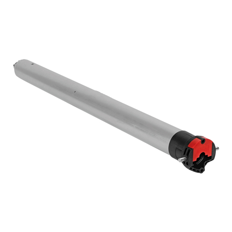
Simu
Simu T5 Hz.02 User manual
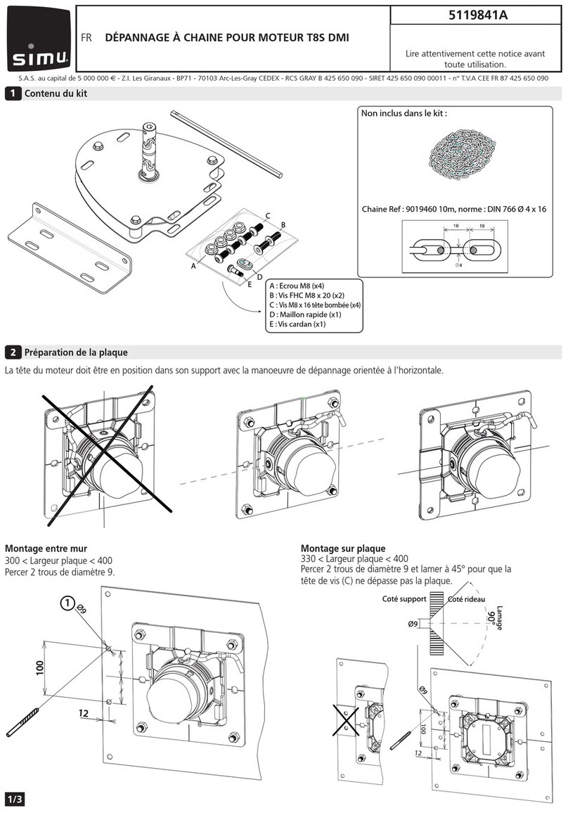
Simu
Simu T8S DMI User manual
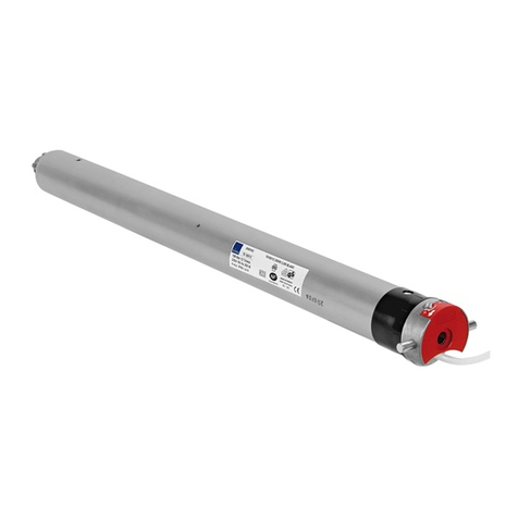
Simu
Simu T3.5 E Hz.02 DC User manual
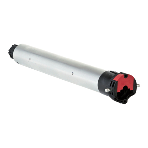
Simu
Simu T5 AUTO SHORT User manual
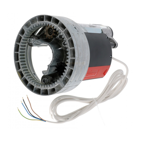
Simu
Simu CENTRIS User manual
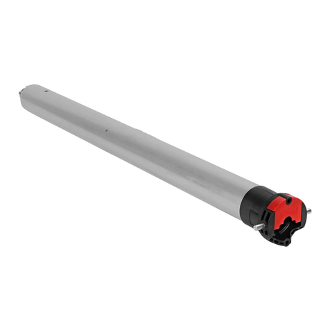
Simu
Simu T5 Hz.02 User manual
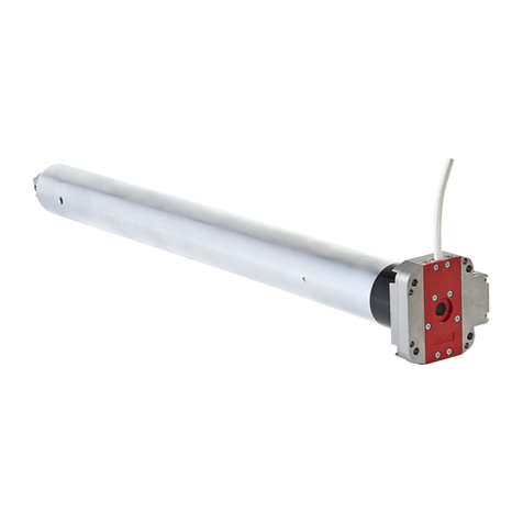
Simu
Simu DMI5 Hz User manual
Simu
Simu T8 User manual
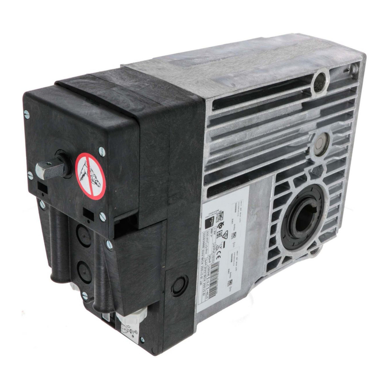
Simu
Simu SIMUBOX 220/12 TRI User manual
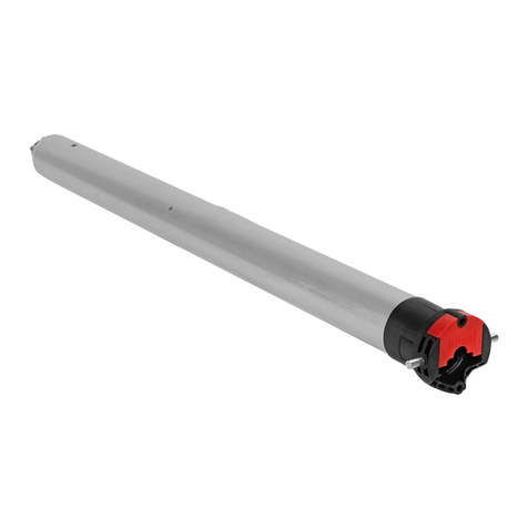
Simu
Simu T5EHz User manual
Popular Engine manuals by other brands

Mitsubishi
Mitsubishi S6B Operation & maintenance manual

Perkins
Perkins 3.152 Series User handbook
rollease acmeda
rollease acmeda AUTOMATE instructions
Omron
Omron ACCURAX G5 - user manual

mycom
mycom NanoDrive INS20 Series user manual

CONTINENTAL AIRCRAFT ENGINE
CONTINENTAL AIRCRAFT ENGINE C75 Series Maintenance manual

