Simu T3.5 DC EHz User manual

Ø min.
(mm)
A
(mm) ØB
(mm) C
(mm) D
(mm) L1
(mm) L2
(mm)
A ØB ØB
A
C
D
L2
L1
29
Ø38,2
T3.5 DC EHz
12 VCC
3Nm - 6Nm - 10Nm 37 433 4,2 8 5,5 457 470
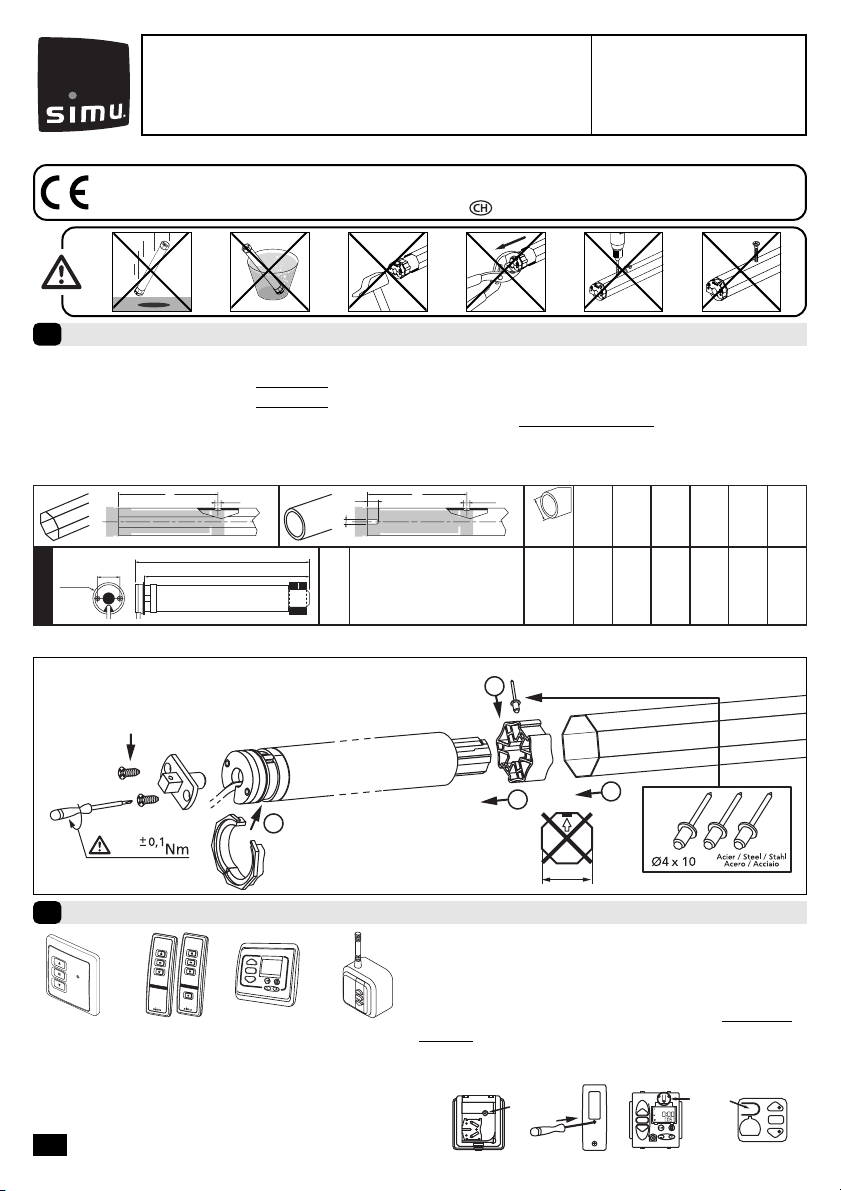
- Perçage du tube :
- Montage :
1/4
1
2
40
3
4
PLASTITE FXS N7\7X12 ZING
1,2
Emetteurs compatibles
2
1 32 4
1: Emetteur Hz mural
2: Emetteurs Hz 1 et 5 canaux
3: Horloge Hz
4: Emetteur Hz “longue portée”
Portée des émetteurs Hz :
- 1, 2 et 3 : 20 m à travers 2 murs de béton armé.
- 4 : 40 m à travers 2 murs de béton armé.
- Eloigner les émetteurs de toute surface ou structure
métallique qui pourraient nuire à leur bon fonctionne-
ment (perte de portée).
Emplacement de la touche “PROG” sur les émetteurs Hz :
PROG PROG
412
3
S.A.S. au capital de 5 000 000 €- Z.I. Les Giranaux - BP71 - 70103 Arc-Les-Gray CEDEX - RCS GRAY B 425 650 090 - SIRET 425 650 090 00011 - n° T.V.A CEE FR 87 425 650 090
!- Préconisations :
- Respecter une distance minimum de 0,2m entre deux moteurs.
- Respecter une distance minimum de 0,3m entre un moteur et un émetteur Hz.
- L’utilisation d’un appareil radio utilisant la même fréquence (433,42MHz) peut dégrader les performances de
ce produit (ex.: casque radio Hi-Fi).
Installation
1
Lire attentivement cette
notice avant toute utilisation.
FT3.5 DC EHz
5055191B
Par la présente SIMU déclare que l’appareil “T3.5 DC EHz” est conforme aux exigences essentielles et autres
dispositions pertinentes de la directive 1999/5/CE. Une déclaration de conformité est mise à votre disposition à
l’adresse internet : www.simu.fr, rubrique “Normes”. Utilisable en
UE,
2/4
batterie 12V - 2.2Ah réf : 9014734
T3.5 DC EHz
>>
!
- Durant les opérations de ce chapître (§3), ne pas travailler sur plusieurs moteurs simultanément.
Réglage des fins de course
3
3.1
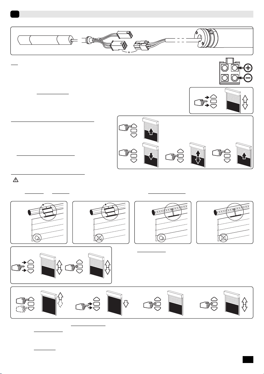
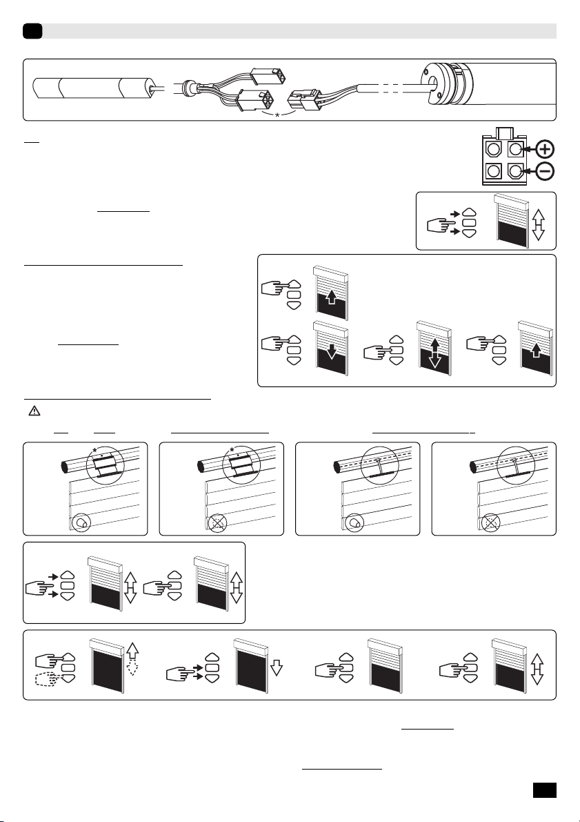
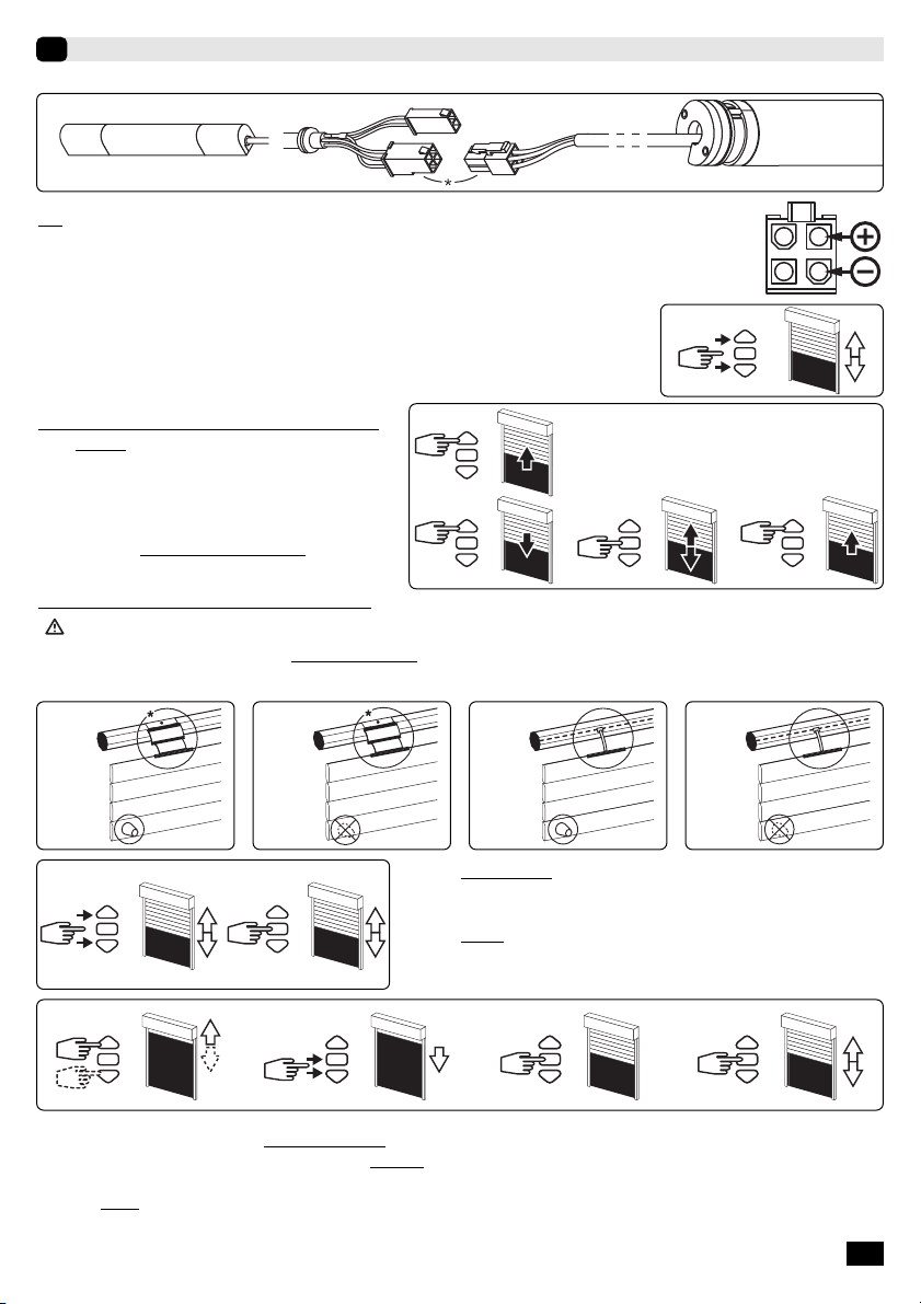
a- Connecter l’alimentation du moteur.
*
Pour plus d’informations sur les caractéristiques des alimentations à utiliser, consulter le
cahier technique SIMU®réf.:5057753
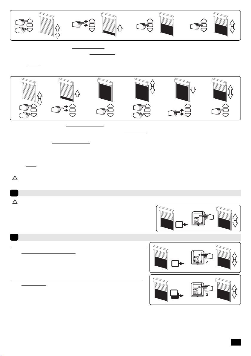
b- Appuyer simultanément sur les touches “montée” et “descente” d’un émet-
teur Hz. Le moteur effectue une rotation de 0,5 seconde dans un sens puis
dans l’autre. Cet émetteur commande maintenant le moteur en mode
instable. Passer à l’étape 3.2.
>>
OK >> 3.3
>> >> >>
3s
>>>>
3.2 - Configuration du sens de rotation
Appuyer sur la touche “montée” de l’émetteur :
a- Si l’axe tourne dans le sens “montée”, passer à
l’étape 3.3.
b- Si l’axe tourne dans le sens “descente”, inverser le
sens de rotation en appuyant sur la touche “stop”
pendant au moins 3 secondes. Le moteur confirme
la modification par une rotation de 0,5 seconde
dans un sens puis dans l’autre. Passer à l’étape 3.3.
3.3 -
Réglage des fins de course
Le réglage des fins de course du moteur T3.5DC EHz s’effectue de 4 façons différentes en fonc-
tion des paramètres suivants :
-Présence ou absence de butées sur la lame finale, liaison souple ou rigide* entre l’axe d’enroulement et
le tablier.
A
*V.A.R
V.A.S
B
*V.A.R
V.A.S
C
D
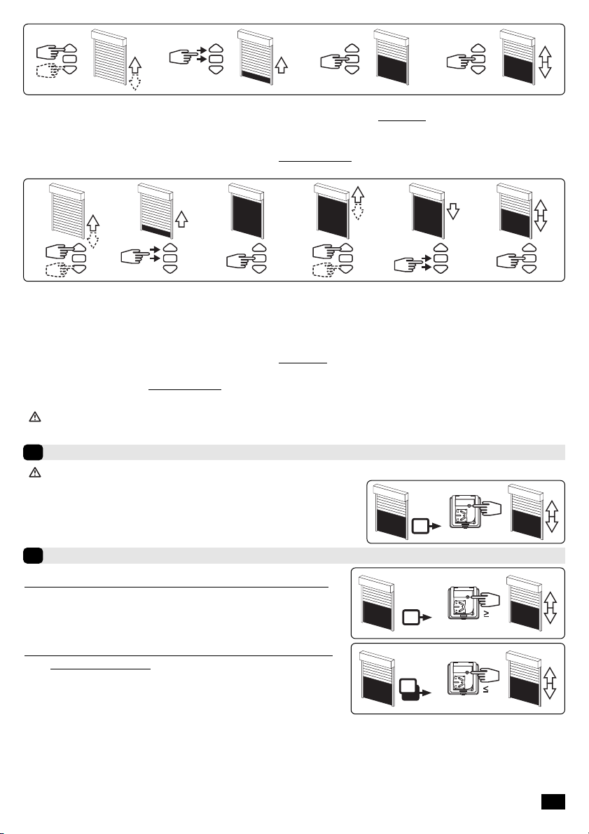
1- Appuyer simultanément sur les touches “montée” et “descente” de
l’émetteur Hz. Le moteur effectue une rotation de 0,5 seconde dans
un sens puis dans l’autre.
2- Appuyer sur la touche “stop”pendant 2 s. le moteur effectue une
rotation de 0,5 s. dans un sens puis dans l’autre. L’opération est ter-
minée. Passer au §4.
12
2s
>> >>
A
>>
2s
1
>>
2
>>
3
>>
4
B
1- Positionner le moteur sur le point d’arrêt haut souhaité à l’aide des touches “montée” et “descente”.
2- Appuyer simultanément sur les touches “stop” et “descente” pour mémoriser le point d’arrêt haut. Le moteur se met
automatiquement en rotation en descente.
3- Appuyer sur la touche “stop” pour immobiliser le moteur.
4- Appuyer 2 secondes sur la touche “stop” pour valider le réglage, le moteur effectue une rotation de 0,5 seconde dans
un sens puis dans l’autre. L’opération est terminée. Passer au §4.

3/4
>>
2s
1
>>
2
>>
3
>>
4
C
1- Positionner le moteur sur le point d’arrêt bas souhaité à l’aide des touches “descente” et“montée”.
2- Appuyer simultanément sur les touches “stop” et “montée” pour mémoriser le point d’arrêt bas. Le moteur se met auto-
matiquement en rotation en montée.
3- Appuyer sur la touche “stop” pour immobiliser le moteur.
4- Appuyer 2 secondes sur la touche “stop” pour valider le réglage, le moteur effectue une rotation de 0,5 seconde dans
un sens puis dans l’autre. L’opération est terminée. Passer au §4.
2 4
2s
61 3 5
D
1- Positionner le moteur sur le point d’arrêt bas souhaité à l’aide des touches “descente” et“montée”.
2- Appuyer simultanément sur les touches “stop” et “montée” pour mémoriser le point d’arrêt bas. Le moteur se met auto-
matiquement en rotation en montée.
3- Lorsque le moteur arrive au point d’arrêt haut souhaité, appuyer sur la touche “stop”.
4- Si nécessaire, affiner le réglage a l’aide des touches “descente” et“montée”.
5- Appuyer sur les touches “stop” et “descente” pour mémoriser le point d’arrêt haut. Le moteur se met automatiquement
en rotation en descente.
6-Appuyer 2 secondes sur la touche “stop” pour valider les réglages fin de course. Le moteur s’arrête puis effectue une
rotation de 0,5 seconde dans un sens puis dans l’autre. L’opération est terminée. Passer au §4.
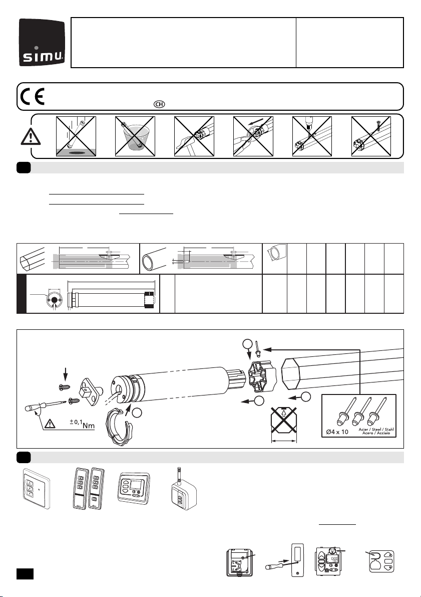
- Après ces opérations vous pouvez programmer l’émetteur utilisé précédemment comme premier point de
commande. Dans ce cas, passez au chapitre §4.
Programmation du premier point de commande individuelle
4
- Cette opération ne peut être effectuée que depuis l’émetteur ayant effectué l’opération 3.1b.
PROG
1s
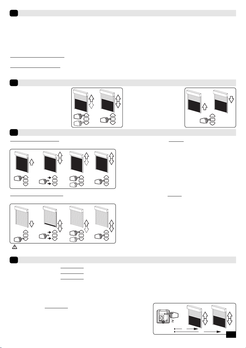
- Appuyer environ 1 seconde sur la touche “PROG” de l’émetteur. Le moteur
effectue une rotation de 0,5 seconde dans un sens puis dans l’autre. Votre
émetteur est maintenant programmé et commande le moteur en
mode stable. Toutes les fonctions décrites §6 sont actives.
Programmation d’un nouveau point de commande (individuelle, groupe ou générale)
5
PROG
3s
5.1 - Ouvrir la mémoire du moteur depuis l’émetteur de commande
individuelle :
- Appuyer environ 3 secondes sur la touche “PROG”de l’émetteur de
commande individuelle. Le moteur effectue une rotation de 0,5 seconde
dans un sens puis dans l’autre.
PROG
1s
5.2 - Valider l’opération depuis le nouvel émetteur à programmer :
- Appuyer environ 1 seconde sur la touche “PROG” du nouvel émetteur.
Le moteur effectue une rotation de 0,5 seconde dans un sens puis dans
l’autre.
- Si votre nouveau point de commande est une commande de groupe : répéter les opérations 5.1 et 5.2 pour
chaque moteur du groupe.
- Si votre nouveau point de commande est une commande générale : répéter les opérations 5.1 et 5.2 pour
chaque moteur de l’installation.
- Pour supprimer un émetteur de la mémoire du moteur : Effectuer les opérations 5.1 depuis l’émetteur de
commande individuelle et l’opération 5.2 depuis l’émetteur à supprimer.

Fonctionnement du moteur T3.5 DC EHz
6
6.1 - Avec une batterie en bon état de charge, les commandes possibles sont : Montée, stop et descente. Il est également
possible de commander une position intermédiaire (voir §7).
6.2 - Fonction détection du gel : Un blocage du volet en présence de gel à la montée provoque l’arrêt du moteur.
6.3 - Fonction détection d’obstacle : Un blocage du volet en présence d’un obstacle à la descente provoque l’arrêt du
moteur, puis une inversion du mouvement.
6.4 - Fonction protection de la batterie contre la décharge excessive : Avant chaque opération de montée ou de des-
cente, le moteur contrôle la tension de la batterie.
Si la tension est inférieure à 11,5V : Le moteur marquera un temps d’arrêt au début de chaque ordre de montée. La des-
cente n’est possible qu’en donnant plusieurs impulsions sur la touche “descente”.
Si la tension est inférieure à 10V : Le récepteur n’acceptera aucun ordre de commande.
Dans les deux cas, utiliser le chargeur de dépannage afin d’effectuer une recharge rapide de la batterie. Le fonc-
tionnnement du moteur redeviendra normal uniquement si la tension de la batterie remonte au dessus de 12V.
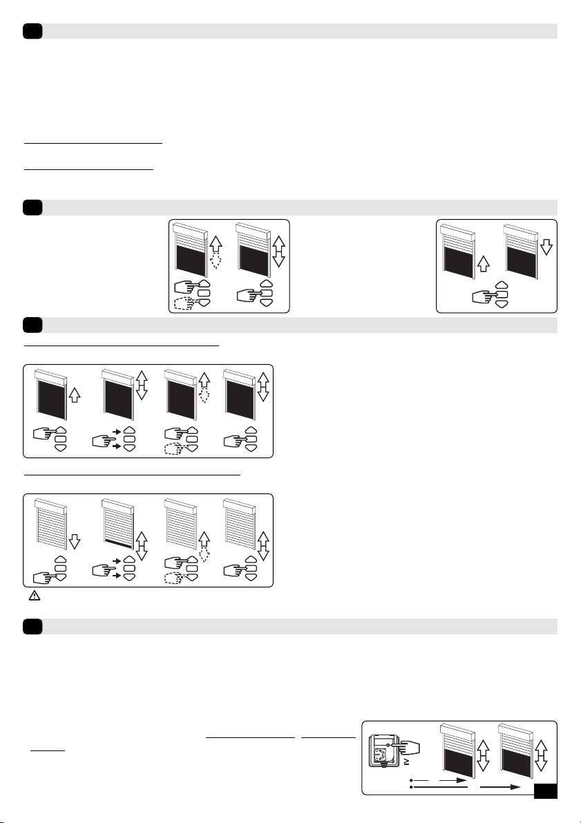
Enregistrement / commande de la position intermédiaire
7
5s
0.5s
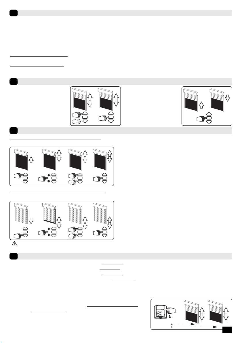
Enregistrement :
- Positionner le moteur sur la
position intermédiaire désirée.
- Appuyer 5s sur la touche
“stop”. Le moteur effectue une
rotation de 1/2 s dans un sens
puis dans l’autre.
Commande :
- Appuyer sur la touche “stop”
pendant 0,5s. Le moteur rejoint
la position intermédiaire.
Ré-ajustement des positions de fins de course
8
Annulation de la programmation
9
9.1 - Couper l’alimentation du moteur pendant 2 secondes.
- Mettre le moteur sous tension pendant 7 secondes.
- Couper l’alimentation du moteur pendant 2 secondes.
- Rétablir l’alimentation du moteur. Celui-ci effectue une rotation dans un sens quelconque pendant 5 secondes.
Le moteur se trouve maintenant en mode annulation de la programmation.
9.2- Ensuite valider l’annulation de la programmation du moteur concerné depuis l’émetteur de commande indi-
viduelle ou depuis un nouvel émetteur.
- Appuyer plus de 7 secondes sur la touche “PROG” de l’émetteur. Maintenir
l’appui jusqu’à ce que le moteur effectue une première rotation de 0,5
seconde dans un sens puis dans l’autre, puis quelques seconde plus tard une
seconde rotation de 0,5 seconde dans les deux sens.
La mémoire du moteur est maintenant complètement vidée. Effectuer
de nouveau la programmation complète du moteur (§3).
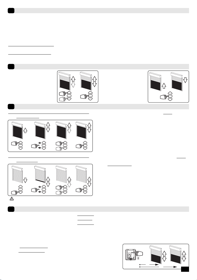
8.1 - Ré-ajustement des positions de fins de
course haut (montages B et D uniquement)
1- Positionner le moteur sur le point d’arrêt haut réglé en §3.3 à
l’aide de la touche “montée”.
2- Appuyer simultanément sur les touches “montée” et “des-
cente” pendant 5 secondes. Le moteur effectue une rotation
de 0,5 seconde dans un sens puis dans l’autre.
3- Affiner le réglage à l’aide des touches “descente” et “montée”
pour obtenir la position de fin de course souhaitée.
4- Appuyer 2 secondes sur la touche “stop”. Le moteur effectue
une rotation de 0,5 seconde dans un sens puis dans l’autre, la
nouvelle position de fin de course est mémorisée.
1 3
2s
4
2
5s
8.2 - Ré-ajustement des positions de fins de
course bas (montages C et D uniquement)
1- Positionner le moteur sur le point d’arrêt bas réglé en §3.3 à
l’aide de la touche “descente”.
2- Appuyer simultanément sur les touches “montée” et “des-
cente” pendant 5 secondes. Le moteur effectue une rotation
de 0,5 seconde dans un sens puis dans l’autre.
3- Affiner le réglage à l’aide des touches “descente” et “montée”
pour obtenir la position de fin de course souhaitée.
4- Appuyer 2 secondes sur la touche “stop”. Le moteur effectue
une rotation de 0,5 seconde dans un sens puis dans l’autre, la
nouvelle position de fin de course est mémorisée.
1 3
2s
4
2
5s
PROG
7s
2s 7s
4/4
- Le ré-ajustement est automatique tous les 56 cycles (pendant 3 cycles) ou après une coupure d’alimenta-
tion dans les cas suivants : Fin de course Haut, montages A et C, Fin de course bas, montages A et B.
Ø min.
(mm)
A
(mm) ØB
(mm) C
(mm) D
(mm) L1
(mm) L2
(mm)
A ØB ØB
A
C
D
L2
L1
29
Ø38,2
T3.5 DC EHz
12 VDC
3Nm - 6Nm - 10Nm 37 433 4,2 8 5,5 457 470
- Drilling of the tube:
- Assembly :
1/4
1
2
40
3
4
PLASTITE FXS N7\7X12 ZING
1,2
Compatible transmitters
2
1: Hz wall transmitter
2: 1 / 5 channels Hz transmitters
3: Hz timer
4: Hz “long range” transmitter
Transmitters range :
- 1, 2 and 3 : 20 m through 2 concrete walls .
- 4 : 40 m through 2 concrete walls.
- Do not position the transmitter near metal surface or
structure in order to avoid range losses.
Location of the “PROG” key on Hz transmitters:
PROG PROG
412
3
S.A.S. au capital de 5 000 000 €- Z.I. Les Giranaux - BP71 - 70103 Arc-Les-Gray CEDEX - RCS GRAY B 425 650 090 - SIRET 425 650 090 00011 - n° T.V.A CEE FR 87 425 650 090
!- Recommendations :
- Keep a minimum distance of 0.2 m between two T3.5 DC EHz motors.
- Keep a minimum distance of 0.3 m between T3.5 DC EHz motors and Hz transmitters.
- A radio appliance using the same frequency (433,42 MHz) may deteriorate our product’s performance (ex. :
hi-fi radio headphones).
Installation
1
Read carefully these
instructions before any use.
GB T3.5 DC EHz
5055191B
Hereby, SIMU, declares that this equipment “T3.5 DC EHz” is in compliance with the essential requirements and other
relevant provision of Directive 1999/5/EC. A declaration of Conformity is available at the web address: www.simu.fr,
heading “Normes”. Usable in UE,
1 32 4

2/4
battery 12V - 2.2Ah réf : 9014734
T3.5 DC EHz
>>
!
- During the operations in this section (§3), do not work on several motors at the same time.
End limits adjustment
3
3.1
a- Connect the motor to the power supply.
*
For any further informations regarding the technical characteristics of power supply, please
consult the technical booklet SIMU®ref.:5059076
b- Press simultaneously on the UP and DOWN buttons of a Hz transmitter. The
motor turns 0.5 second in one direction, then in the other.
This transmitter now commands the motor in unstable mode. Go to
step 3.2
>>
OK >> 3.3
>> >> >>
3s
>>>>
3.2 - Test and setting the direction of rotation
Press on the UP button on the transmitter:
a- If the shaft turns in the UP direction, go to step §3.3
b- If the motorized tube runs in the DOWN direction,
reverse the rotation direction by pressing the STOP
key for at least 3 seconds. The motor will confirm
the reversal of the rotation direction by running 0.5
second in both directions. Go to step 3.3.
3.3 -
End limits adjustment
The end limits of the T3.5 DC EHz are adjusted in 4 different ways depending on the following
conditions:
-Bottom slat stop or not, stiff or flexible* link between the rolling shaft and the shutter.
A
*V.A.R
V.A.S
B
*V.A.R
V.A.S
C
D
1- Simultaneously press the UP and DOWN keys of a Hz trans-
mitter. The motor will run for 0.5 second in one direction
and then in the other.
2- Press the “stop” key for 2 s. The motor will run for 0.5
second in one direction and then in the other. The operation
is completed. Go to step §4.
12
2s
>> >>
A
>>
2s
1
>>
2
>>
3
>>
4
B
1- Position the motor on the UP end limit by using the keys UP or DOWN.
2- To memorize the UP end limit position, press simultaneoulsy the keys STOP and DOWN. The motor will run
automatically in the DOWN direction.
3- Press the STOP key to immobilize the motor.
4- Press 2 seconds the STOP key to validate the setting. The motor will run for 0,5 second in one direction, then
in the other direction. The operation is completed. Go to step §4.

3/4
>>
2s
1
>>
2
>>
3
>>
4
C
1- Position the motor on the DOWN end limit by using the keys UP or DOWN.
2- To memorize the DOWN end limit position, press simultaneoulsy the keys STOP and UP. The motor will run
automatically in the UP direction.
3- Press the STOP key to immobilize the motor.
4- Press 2 seconds the STOP key to validate the setting. The motor will run for 0.5 second in one direction, then
in the other. The operation is completed. Go to step §4.
2 4
2s
61 3 5
D
1- Position the motor on the DOWN end limit by using the keys DOWN or UP.
2- To memorize the DOWN end limit position, press simultaneoulsy the keys STOP and UP. The motor will run
automatically in the UP direction.
3- When the motor arrives on the UP End limit, press the key STOP.
4- If necessary adjust the position with the keys UP or DOWN.
5- To memorize the UP end limit position, press simultaneoulsy the keys STOP and DOWN. The motor will run
automatically in the DOWN direction.
6- Press 2 seconds the STOP key to validate the setting. The motor will stop, and will run for 0.5 second in one
direction, then in the other. The operation is completed. Go to step §4
- After these operations, you can program the transmitter used before as a 1st control point. To do so, see
chapter §4.
Programming the first individual control point
4
- This operation can only be performed from the transmitter that was used for operation 3.1b.
PROG
1s
- Press the transmitter “PROG” Key for approximately one second. The
motor will run for 0.5 second in one direction and then in the other.
Your transmitter is now programmed to control the motor in
stable mode. All the functions described in §6 are active.
Programming a new (individual, group or main) control point
5
PROG
3s
5.1 - Open the memory of the receiver from the control
transmitter:
- Press the “PROG” key of the transmitter for about 3 seconds.
The motor will run for 0.5 second in one direction and then in
the other.
PROG
1s
5.2 - Validate the operation from the new transmitter you
want to programm:
- Press the “PROG” key of the transmitter for about 1 second. The
motor will run for 0.5 second in one direction and then in the
other.
- For group controls, repeat operations 5.1 and 5.2 for each motor in the group.
- For main controls, repeat operations 5.1 and 5.2 for each motor in the installation.
- To delete an transmitter from the memory of a motor, perform operations 5.1 with a programmed transmitter,
then perform the operation 5.2 with the transmitter to be deleted.
T3.5 DC EHz motor functions
6
6.1 -
With a well charged battery, the possible commands are: Up, stop and down. It is also possible to set an
intermediate position (see §7).
6.2 -
Frost detection function: The motor stops if the shutter is jammed by ice during opening.
6.3 -
Detection of obstructions function: Jamming of the shutter due to the presence of an obstruction
when closing the shutter causes the motor to stop and then run in the reverse direction.
6.4 -
Battery protection against excessive discharge: Before each lifting or lowering of the shutter, the
motor checks the voltage of the battery.
If the voltage is below 11.5V: The motor will pause at the beginning of each command to lift the shutter. The
shutter can only be closed by pressing several times on the "down" button.
If the voltage is below 10V: The receiver won’t accept any commands.
In these two cases, use the emergency charger in order to perform a quick battery recharge.
Operation of the motor will return to normal only if the battery voltage goes above 12V.
Recording and controling intermediate position
7
5s
0.5s
Recording:
- Position the motor on the
wanted position.
- Press 5 seconds on the “stop”
key. The motor will run for
0.5 second in one direction
and then in the other.
Controling:
- Press on the “stop” key for
0.5 s. the motor goes to the
intermediate position.
Re-adjustement of end limits
8
Cancelling programming
9
9.1 - Switch off the power supply to the motor for 2 seconds.
- Switch on the power supply to the motor for 7 seconds.
- Switch off the power supply to the motor for 2 seconds.
- Switch the power to the motor back on. The motor will run for 5 seconds in random direction and is
now in the “cancelling” mode.
9.2-
Then, validate the cancelling of the affected motor from the individual control or from a new transmitter
- Press the “PROG” key of the transmitter more than 7 seconds. Maintain the
pressure until the motor will first run for 0.5 second in one direction and
then in the other, and a few second later, it will run again in both direction.
The motor is now as it was originally configured, and no transmitter and no
settings is saved in its memory and is ready for a new programming (§3).
8.1 -
Re-adjustement of UP end limits:
(assemblies B and D only)
1- Position the motor on the UP end limit previously set in §3.3
with the UP key.
2- Press simultaneously for 5 seconds the UP and DOWN keys, the
motor will run for 0.5 second in one direction and then in the
other direction.
3- Adjust the new position with the UP and DOWN keys.
4- Validate the new position by pressing 2 seconds the STOP key.
The motor will run for 0.5 second in one direction and then in
the other direction. The new end limits setting is memorized.
1 3
2s
4
2
5s
8.2 -
Re-adjustement of DOWN end limits:
(assemblies C and D only)
1- Position the motor on the DOWN end limit previously set in §3.3
with the DOWN key.
2- Press simultaneously for 5 secondes the UP and DOWN keys, the
motor will run for 0.5 second in one direction and then in the
other direction.
3- Adjust the new position with the UP and DOWN keys.
4- Validate the new position by pressing 2 seconds the STOP key.
The motor will run for 0.5 second in one direction and then in
the other direction. The new end limits setting is memorized.
1 3
2s
4
2
5s
PROG
7s
2s 7s
4/4
- The re-adjustment of end limits is automatic every 56 cycles (during 3 cycles) or after a power supply failure
for the following installation : Up end limit, mounting A and C, Down end limit, mounting A and B.

Ø min.
(mm)
A
(mm) ØB
(mm) C
(mm) D
(mm) L1
(mm) L2
(mm)
A ØB ØB
A
C
D
L2
L1
29
Ø38,2
T3.5 DC EHz
12 VDC
3Nm - 6Nm - 10Nm 37 433 4,2 8 5,5 457 470
- Bohrungen in der Welle:
- Montage :
1/4
1
2
40
3
4
PLASTITE FXS N7\7X12 ZING
1,2
Kompatible Sender
2
1 32 4
1:
Hz Wandsender
2:
Hz 1 und 5 kanalsender
3:
Hz-Uhr
4:
Hz-Sender mit “grosse Reichweite”
Senderreichweiten:
- 1, 2 und 3 : 20m durch 2 Stahlbetonwände.
- 4 : 40m durch 2 Stahlbetonwände.
- Bewahren Sie den Sender nicht in der Nähe metallischer
Objekte auf; diese könnten die Senderleistung beein-
flussen (geringere Reichweite).
Anordnung der “Prog” Taste am Hz-Sender:
PROG PROG
412
3
S.A.S. au capital de 5 000 000 €- Z.I. Les Giranaux - BP71 - 70103 Arc-Les-Gray CEDEX - RCS GRAY B 425 650 090 - SIRET 425 650 090 00011 - n° T.V.A CEE FR 87 425 650 090
!- Empfehlungen :
- Halten Sie eine Mindestdistanz von 0,2m zwischen zwei Motoren T3.5 DC EHz ein.
- Halten Sie eine Mindestdistanz von 0,3m zwischen Motoren und Hz-Funksendern ein.
- Ein Radiogerät, das die gleiche Frequenz nutzt (433,42 MHz), könnte die Leistung des Produkts stören (z.B. Hi-
Fi Radio-Kopfhörer).
Installation
1
Bitte gründlich vor der
Anwendung lesen.
DT3.5 DC EHz
5055191B
Hiermit erklärt SIMU, dass sich dieses Produkt “T3.5 DC EHz” in Übereinstimmung mit den grundlegenden Anforderungen
und den anderen relevanten Vorschriften der Richtlinie 1999/5/EG befindet. Eine Erklärung der Konformität kann au der
WEB-Site : www.simu.fr, unter Abschnitt “Normes” abgerufen werden. verwendbar in UE,
2/4
Akku. 12V - 2.2Ah Art.-Nr. 9014734
T3.5 DC EHz
>>
!
Immer nur einen Motor in Empfangsbereitschaft setzen.
Einstellung Endbegrenzung
3
3.1
a- Verbinden Sie den Motor mit dem Batteriepaketes.
- Weitere Informationen über die technische Eigenschaften des Batteriepakets finden Sie in der
technischen Dokumentation SIMU®Art.Nr.:5059076
b- Drücken Sie gleichzeitig die AUF- und AB-Taste eines Hz Senders. Der Motor
läuft 0,5 Sekunde in die eine, dann in die andere Richtung. Der Sender
steuert nun den Motor im Totmannbetrieb. Siehe Schritt 3.2.
>>
OK >> 3.3
>> >> >>
3s
>>>>
3.2 - Überprüfen der Laufrichtung
Drücken Sie die AUF-Taste am Sender:
a- Wenn sich das Rollladenelement mit Motor nach oben
bewegt, wechseln Sie zum nächsten Schritt (3.3).
b- Wenn sich das Rollladenelement mit Motor nach unten
bewegt, ändern Sie die Richtung, indem Sie die STOP-
Taste mindestens 3 S. lang gedrückt halten. Der
Empfänger bestätigt den Richtungswechsel und dreht
0,5 S. lang in die eine, dann in die andere Richtung.
Weiter mit Schritt 3.3.
3.3 -
Einstellung der Endbegrenzung
Die Art der Einstellung der Endbegrenzung hängt von den vier folgenden Montagesituationen ab:
- Mit oder ohne Endstopper, feste Wellenverbinder* (V.A.R oder V.A.S) oder flexible Aufhängefedern für den Behang.
A
*V.A.R
V.A.S
B
*V.A.R
V.A.S
C
D
1- Drücken Sie gleichzeitig die AUF und die AB Taste des
Senders. Der Motor läuft für 0,5 Sekunde in die eine und in
die andere Richtung.
2- Drücken Sie die STOP Taste für 2 Sekunden. Der Motor läuft
für 0,5 Sekunde in die eine und in die andere Richtung. Die
Einstellung ist beendet. Weiter mit Schritt §4.
12
2s
>> >>
A
>>
2s
1
>>
2
>>
3
>>
4
B
1- Fahren Sie den Motor mit den AUF und AB Tasten in die obere Endposition.
2- Um die obere Endlage zu speichern , drücken Sie die STOP und die AB Taste gleichzeitig. Der Motor fährt
jetzt in AB Richtung.
3- Drücken Sie jetzt die STOP Taste um den Motor anzuhalten.
4- Zur Speicherung der Endbegrenzung OBEN drücken Sie 2 Sekunden lang die STOP Taste. Der Motor läuft
0,5 Sekunde in die eine, dann in die andere Richtung. Weiter mit Schritt §4.
3/4
>>
2s
1
>>
2
>>
3
>>
4
C
1- Fahren Sie den Motor mit den AUF und AB Tasten in die untere Endposition.
2- Um die untere Endlage zu speichern , drücken Sie die STOP und die AUF Taste gleichzeitig. Der Motor fährt jetzt in AUF
Richtung.
3- Drücken Sie jetzt die STOP Taste um den Motor anzuhalten.
4- Zur Speicherung der Endbegrenzung OBEN drücken Sie 2 Sekunden lang die STOP Taste. Der Motor läuft 0,5 Sekunde in
die eine, dann in die andere Richtung. Weiter mit Schritt §4.
2 4
2s
61 3 5
D
1- Positionieren Sie den Motor mit den AUF- oder AB Tasten an der Endbegrenzung UNTEN.
2- Zur Speicherung der Endbegrenzung UNTEN drücken Sie gleichzeitig die Tasten STOP und AUF. Der Motor läuft automa-
tisch aufwärts
3- Wenn der Motor das Endbegrenzung OBEN erreicht, drücken Sie die Taste STOP.
4- Justieren Sie die Position gegebenenfalls mit den AUF- oder AB Tasten.
5- Zur Speicherung der Endbegrenzung OBEN drücken Sie gleichzeitig die Tasten STOP & NACH UNTEN. Der Motor läuft
automatisch abwärts.
6- Halten Sie die Taste STOP 2 Sekunden lang gedrückt, um die Einstellung zu bestätigen. Der Motor stoppt und läuft 0,5
Sekunde in die eine, dann in die andere Richtung. Weiter mit Schritt §4.
- Nach diesen Einstellungen können Sie den zuvor verwendeten Sender speichern. Hierzu beachten Sie
Schritt §4.
Programmierung des ersten individuellen Steuerpunkts
4
- Diese Einstellung kann nur für den unter Punkt 3.1b verwendeten Sender vorgenommen werden.
PROG
1s
- Halten Sie die Taste “PROG” ca. 1 Sekunde lang gedrückt. Der Motor läuft
0,5 Sekunde in die eine, dann in die andere Richtung.
Ihr Sender ist nun so programmiert, dass er den Motor zuverlässig
steuert.Es sind alle in §6 beschriebenen Funktionen aktiv.
Programmierung eines neuen (individuellen, Gruppen- oder Haupt-) Steuerpunkts
5
PROG
3s
5.1 - Vorbereitung des Motors für einen weiteren Sender:
- Halten Sie die Taste “PROG” des Senders ca. 3 Sekunden lang
gedrückt. Der Motor läuft 0,5 Sekunde in die eine, dann in die
andere Richtung.
PROG
1s
5.2 - Bestätigen Sie die Eingaben an dem neu zu program-
mierenden Sender:
- Halten Sie die Taste “PROG” des Senders ca. 1 Sekunde lang
gedrückt. Der Motor läuft 0,5 Sekunde in die eine, dann in die
andere Richtung.
- Für Gruppensteuerungen wiederholen Sie die Schritte 5.1 und 5.2 für jeden Motor der Gruppe.
- Für die Hauptsteuerung wiederholen Sie die Schritte 5.1 und 5.2 für jeden Motor der Installation.
- Um einen Sender aus dem Speicher des Motors zu löschen, wiederholen Sie Schritt 5.1 mit einem
programmierten Sender und dann Schritt 5.2 mit dem zu löschenden Sender.
Betriebsweise vom Motor T3.5 DC EHz
6
6.1 - Bei einer ordentlich geladenen Batterie, sind die möglichen Befehle: aufwärts, Halt und abwärts. Es kann auch eine
Zwischenstellung angesteuert werden (siehe §7).
6.2 - Funktion Frosterfassung: Eine Sperrung des Rolladens wegen Frost führt zum Motorstillstand.
6.3 - Funktion Hinderniserfassung: Eine Sperrung des Rolladens wegen Vorhandensein eines Hindernisses in der
Abwärtsbewegung führt zum Motorstillstand, und dann zu einer Bewegungsumkehr.
6.4 - Funktion Batterieschutz gegen eine zu starke Entladung: Vor jeder Aufwärts- oder Abwärtsbewegung, führt der
Motor eine Spannungskontrolle der Batterie durch.
Bei einer Spannung unter 11,5V: hält der Motor bei Beginn jedes Aufwärtsbefehls kurz an. Die Abwärtsbewegung ist nur
durch mehrere Impulse auf die Taste "Abwärts" möglich.
Bei einer Spannung unter 10V: Nimmt der Empfänger keinen Steuerbefehl an.
In beiden Fällen, das Ladegerät benutzen, um eine schnelle Batterienachladung durchzuführen. Der
Motorbetrieb wird erst wieder normal, nachdem die Batteriespannung über 12V gestiegen ist.
Speichern und Kontrolle der Zwischenpositionen
7
5s
0.5s
Speichern:
- Fahren Sie den Motor in die
gewünschte Position.
- Halten Sie 5 Sekunden die STOP
Taste gedrückt. Der Motor fährt
0,5 Sekunde in die eine, dann in
die andere Richtung.
Kontrolle:
- Halten Sie 0,5 Sekunde die
STOP Taste gedrückt. Der
Motor fährt an die gespei-
cherte Zwischenposition.
Neueinstellung der Endbegrenzung
8
Löschen der Programmierung
9
9.1 - Schalten Sie die Stromversorgung des Motors 2 Sekunden lang ab.
- Schalten Sie die Stromversorgung des Motors 7 Sekunden lang ein.
- Schalten Sie die Stromversorgung des Motors 2 Sekunden lang ab.
- Schalten Sie den Motor wieder ein. Der Motor läuft 5 Sekunden lang.
Der Motor ist im “Modus Löschen”.
9.2- Bestätigen Sie dann das Löschen des entsprechendes Motors an der Einzelsteuerung oder mit einem neuen
Sender:
- Halten Sie die Taste “PROG” des Senders mindestens 7 Sekunden lang
gedrückt. Halten Sie die Taste so lange gedrückt, bis der Motor 2 x eine Auf-
und Abwärtsbewegung fährt.
Nun ist der Motor auf die Werkseinstellungen zurückgesetzt. Es sind
keine Sender und Einstellungen mehr im Speicher programmiert.
8.1 - Neueinstellung der Endbegrenzung OBEN
(Nur für Montageart B und D) 1- Fahren Sie den Motor in die obere Endlage.
2- Halten Sie die AUF und AB Tasten 5 Sekunden lang gleichzei-
tig gedrückt. Der Motor läuft 0,5 Sekunde lang in die eine,
dann in die andere Richtung.
3- Stellen Sie die neue Position mit den AUF oder AB Tasten ein.
4- Bestätigen Sie die neue Position, indem Sie die STOP Taste 2
Sekunden lang gedrückt halten. Der Motor läuft 0,5 Sekunde
lang in die eine, dann in die andere Richtung.
1 3
2s
4
2
5s
8.2 - Neueinstellung der Endbegrenzung UNTEN
(Nur für Montageart C und D) 1- Fahren Sie den Motor in die untere Endlage.
2- Halten Sie die AUF und AB Tasten 5 Sekunden lang gleichzei-
tig gedrückt. Der Motor läuft 0,5 Sekunde lang in die eine,
dann in die andere Richtung.
3- Stellen Sie die neue Position mit den AUF oder AB Tasten ein.
4- Bestätigen Sie die neue Position, indem Sie die STOP Taste 2
Sekunden lang gedrückt halten. Der Motor läuft 0,5 Sekunde
lang in die eine, dann in die andere Richtung.
1 3
2s
4
2
5s
PROG
7s
2s 7s
4/4
- Die Neueinstellung der Endlagen erfolgt alle 56 Zyken (3 Zyklen lang) oder nach Spannungsverlust bei de
folgenden Installationsmodi: Obere Endlage: Modus A und C, Untere Endlage: Modus A und B.
Ø min.
(mm)
A
(mm) ØB
(mm) C
(mm) D
(mm) L1
(mm) L2
(mm)
A ØB ØB
A
C
D
L2
L1
29
Ø38,2
T3.5 DC EHz
12 VDC
3Nm - 6Nm - 10Nm 37 433 4,2 8 5,5 457 470
- Het Boren van de gaten :
- Montage :
1/4
1
2
40
3
4
PLASTITE FXS N7\7X12 ZING
1,2
Compatibele zenders
2
1 32 4
1: Hz Wandzender
2: Zender Hz 1 en 5 kanalen
3: Hz-Klok
4: Zender Hz “lange reikwijdte”
Hz Zender reikwijdte:
- 1, 2 en 3 : 20m door 2 muren van gewapend beton.
- 4 : 40m door 2 muren van gewapend beton.
- Zet de zender niet tegen of in de buurt van een meta-
len deel, het bereik zal dan namzlijk kleiner zijn.
Plaats van de toets “PROG” op de zenders Hz:
PROG PROG
412
3
S.A.S. au capital de 5 000 000 €- Z.I. Les Giranaux - BP71 - 70103 Arc-Les-Gray CEDEX - RCS GRAY B 425 650 090 - SIRET 425 650 090 00011 - n° T.V.A CEE FR 87 425 650 090
!- Adviezen :
- Bewaar een minimum afstand van 20 cm tussen twee motor.
- Bewaar een minimum afstand van 30 cm tussen een motor en een zender Hz.
- Een radiotoepassing (bij. hi-fi hoofdtelefoon) die gebruikt maakt van dezelfde frequencie (433,42MHz). kan de
performance van onze producten nadelig beïnvloeden.
Installatie
1
Deze handleiding aandachtig
doorlezen alvorens het
systeem te gebruiken.
NL T3.5 DC EHz
5055191B
Hierbij verklaart SIMU dat het toestel “T3.5DC E Hz” overeenstemming is met de essentiële eisen en de andere
relevante bepalingen van richtlijn 1999/5/EG. Een conformiteitsverklaring staat ter beschikking op het internetadres :
www.simu.fr, onder de rubriek “Normes”. Bruikbaar in UE,
2/4
batterijpack 12V - 2.2Ah ref : 9014734
T3.5 DC EHz
>>
!- Met een motor tegelijk werke.
Instelling van de stop van de motor
3
3.1
a- Zet de motor onder spanning.
*
Raadpleeg voor meer informatie over de kenmerken van de te gebruiken voedingen het tech-
nisch cahier SIMU® ref.:5059076
b- Druk vervolgens tegelijkertijd, op de toetsen omhoog en omlaag van een zen-
der, de motor draait 0,5 seconde in een richting en vervolgens in een andere
richting.
Deze zender bedient nu de motor in onstabiele mode. Ga naar 3.2.
>>
OK >> 3.3
>> >> >>
3s
>>>>
3.2 -
Controle van de draairichting van de
motor
Druk op de OP knop van de zender :
a- Als het luik omhoog gaat, gaat u verder naar
de stap 3.3.
b- Als het luik daalt, verander dan de draairich-
ting door tenminste 3 seconden op de toets
“STOP” te drukken. Ga naar 3.3.
3.3 -
Instelling van de stop van de motor
De eindschakelaars van de T3.5DC EHz moeten, afhankelijk van de volgende parameters worden
ingesteld : Aanslag of niet, vaste of flexibele* verbinding naar lamellen.
A
*V.A.R
V.A.S
B
*V.A.R
V.A.S
C
D
1- Druk tegelijkertijd op de OP en NEER knopppen van de Hz
zender. De motor zal bevestigen door in beide richtingen
kort te bewegen.
2- Druk 2 sec. op STOP. De motor zal bevestigen door in beide
richtingen kort te bewegen. De eindschakelaars zijn nu
geprogrammeerd. Ga naar stap 4.
12
2s
>> >>
A
>>
2s
1
>>
2
>>
3
>>
4
B
1- Positioneer de motor in de bovenste positie m.b.v. de drukknoppen OP en NEER.
2- Om de bovenste positie op te slaan druk tegelijk op STOP en NEER. De motor gaat naar beneden lopen.
3- Druk op STOP om de motor te stoppen.
4- Druk 2 sec. op STOP om de instellingen vast te leggen. De motor zal bevestigen door in beide richtingen kort
te bewegen. Ga naar stap 4.
3/4
>>
2s
1
>>
2
>>
3
>>
4
C
1- Positioneer de motor in de onderste positie m.b.v. de drukknoppen OP en NEER.
2- Om de onderste positie op te slaan druk tegelijk op STOP en OP. De motor gaat naar boven lopen.
3- Druk op STOP om de motor te stoppen.
4- Druk 2 sec. op STOP om de instellingen vast te leggen. De motor zal bevestigen door in beide richtingen kort
te bewegen. Ga naar stap 4.
2 4
2s
61 3 5
D
1- Positioneer de motor in de bovenste eindpositie met de knoppen OP en NEER.
2- Om de onderste positie op te slaan in het geheugen, druk tegelijkertijd de knoppen STOP & OP. De motor zal dan auto-
matisch naar boven gaan lopen.
3- Als de motor bij de bovenste eindpositie aankomt, druk op STOP.
4- Verander de positie, indien nodig, met de knoppen OP en NEER.
5- Om de bovenste positie op te slaan in het geheugen, druk tegelijkertijd de konoppen STOP & NEER. De motor zal auto-
matisch naar beneden gaan lopen.
6- Druk 2 sec. op STOP om de instellingen op te slaan. De motor zal stoppen en dan in elke richting een halve seconde
gaan draaien. Ga naar stap 4.
- Nu kunt u de gebruikte zender toewijzen aan de motor. Zie stap 4
Programmering als individueel bedienpunt
4
- Deze procedure geldt alleen voor een zender die procedure 3.1b. al heeft doorlopen.
PROG
1s
- Druk ongeveer 1 sec. op de toets “PROG” van de zender. De motor draait
0,5 seconde in een richting en vervolgens in de andere richting. Uw zender
is nu geprogrammeerd om de motor in de stabiele mode te besturen.
Alle in §6 beschreven functies zijn actief.
Programmeren van een andere zender (individueel, groep of hoofdzender)
5
PROG
3s
5.1 - Open het geheugen van de ontvanger vanuit de indivi-
duele bedieningszender
- Druk ongeveer 3 sec. op de toets “PROG” van de individuele
bedieningszender. De motor draait 0,5 seconde in een richting en
vervolgens in de andere richting.
PROG
1s
5.2 - Valideer de operatie vanuit de andere te programme-
ren zender
- Druk ongeveer 1 sec. op de toets “PROG” van de nieuwe zender.
De motor draait 0,5 seconde in een richting en vervolgens in de
andere richting.
- Voor een gegroepeerde bediening met de andere zender: voer de operaties 5.1 en 5.2 uit voor iedere motor
van de betreffende groep.
-Voor een algemene bediening met de andere zender: voer de operaties 5.1 en 5.2 uit voor iedere motor van
de installatie.
- Om een zender uit het geheugen van een ontvanger te wissen, volg procedure 5.1 met een geprogrammeerde
zender, Volg daarna procedure 5.2 met de zender die gewist moet worden.
Werking van de motor T3.5 DC EHz
6
6.1 - Met een goed geladen batterij zijn de volgende bedieningen mogelijk: stijging, stop en daling. Het bedienen van een
tussenstand is eveneens mogelijk (zie §7).
6.2 -
Detectiefunctie van vorst: een blokkering van het luik tijdens het stijgen in geval van vorst veroorzaakt het stoppen van de motor.
6.3 - Detectiefunctie van obstakel: een blokkering van het luik tijdens het dalen bij een obstakel veroorzaakt het stoppen
van de motor en daarna een omzetten van de beweging.
6.4 - Beschermingsfunctie van de batterij tegen overmatige ontlading: de motor controleert voor elke uitvoering van stijging
of daling de spanning van de batterij.
Bij een spanning onder 11,5V: de motor stopt een moment bij het begin van elke bediening van stijging. De daling is alleen
mogelijk met meerdere drukken op toets “daling”.
Bij een spanning onder 10V: de receptor accepteert geen enkele bediening.
Gebruik in beide gevallen, de noodlader om een snelle lading van de batterij te realiseren. De motor
gaat weer normaal werken wanneer de spanning van de batterij boven 12V komt.
Programmeren en oproepen van de tussenpositie
7
5s
0.5s
Programeren
- De motor op de gewenste
positie instellen.
- Druk 5s op de toets "stop".
De motor draait 0,5
sec.
in
een richting en vervolgens
in de andere richting.
Oproepen :
- Druk 0,5
sec.
op de toets
"stop". De motor loopt
naar de ingestelde tussen-
positie.
Her- instellen van de eindeloopposities
8
Het wissen van de programmering
9
9.1 - Schakel gedurende 2 seconden de voeding van de ontvanger uit.
- Schakel gedurende 7 seconden de voeding van de ontvanger weer in.
- Schakel gedurende 2 seconden de voeding van de ontvanger uit.
- Schakel de voeding van de ontvanger weer in, de motor draait 5 seconden.
De motor is in de annuleringsmodus.
9.2- Valideer het wissen van de betreffende ontvanger vanuit de individuele bedieningszender of
van een nieuwe zender.
- Druk meer dan 7 seconden op de toets PROG” van de individuele
bedieningszender. Houdt deze toetsindedrukt totdat, de motor
draait 0,5
sec.
in een richting en vervolgens in de andere richting en
enkele seconden later in beide richtingen.
De T3.5DC EHz motor is nu helemaal gewist en terug in de
staat waarin u hem af fabriek geleverd krijgt.
8.1 - OP eindafstelling (alleen samenstelling
tek. B &D)
1- Positioneer de motor in de bovenste (reeds ingestelde) eindpositie.
2- Druk de knoppen OP en NEER gedurende 5 sec. tegelijkertijd
in.De motor draait 0,5 sec. in een richting en vervolgens in de
andere richting.
3- Beweeg de motor naar de gewenste nieuwe positie met de
OP en NEER knoppen.
4- Bevestig de nieuwe positie door 2 sec. Op STOP te drukken.
De motor draait 0,5 sec. in een richting en vervolgens in de
andere richting.
1 3
2s
4
2
5s
8.2 - Neer eindafstelling (Alleen samenstelling
tek. C & D)
1- Positioneer de motor in de onderste (reeds ingestelde) eindpositie.
2- Druk de knoppen OP en NEER gedurende 5 sec. tegelijkertijd
in. De motor draait 0,5 sec. in een richting en vervolgens in
de andere richting.
3- Beweeg de motor naar de gewenste nieuwe positie met de
OP en NEER knoppen.
4- Bevestig de nieuwe positie door 2 sec. Op STOP te drukken.
De motor draait 0,5 sec. in een richting en vervolgens in de
andere richting.
1 3
2s
4
2
5s
PROG
7s
2s 7s
4/4
- Her-instelling van de eindschakelaar(s) gebeurt automatisch iedere 56 cycli gedurende 3 cycli, of na een stroommuitval. Dit
geldt voor de volgende instalatiewijzen : Op-eindschakelaar : installatiewije A en C, Neer-eindschakelaar : installatiewije A en B.

Ø min.
(mm)
A
(mm) ØB
(mm) C
(mm) D
(mm) L1
(mm) L2
(mm)
A ØB ØB
A
C
D
L2
L1
29
Ø38,2
T3.5 DC EHz
12 VCC
3Nm - 6Nm - 10Nm 37 433 4,2 8 5,5 457 470
- Perforación del tubo:
- Montage :
1/4
1
2
40
3
4
PLASTITE FXS N7\7X12 ZING
1,2
Emisores compatibles
2
1 32 4
1: Emisor Hz mural
2: Emisores Hz 1 y 5 canales
3: Reloj Hz
4: Emisor Hz “largo alcance”
Alcance de los emisores:
1, 2 y 3: 20 mts a través 2 paredes de hormigón armado
4: 40 mts a través 2 paredes de hormigón armado
- Alejar los emisores de todas la superficies metálicas que
pudieran resultar nocivas para su buen funcionamiento
(pérdida de alcance).
Emplazamiento de la tecla “PROG” en los emisores Hz:
PROG PROG
412
3
S.A.S. au capital de 5 000 000 €- Z.I. Les Giranaux - BP71 - 70103 Arc-Les-Gray CEDEX - RCS GRAY B 425 650 090 - SIRET 425 650 090 00011 - n° T.V.A CEE FR 87 425 650 090
!- Consejos :
- Respetar una distancia mínima de 20 cm entre dos motores.
- Respetar una distancia mínima de 30 cm entre un motor y un emisor Hz.
- La utilización de un aparato de radio con las mismas frecuencias (433,42MHz) puede degradar las prestaciones
de nuestro equipo.(ej: casco de radio hi-fi).
Installation
1
leer atentamente este folleto
antes de cualquier utilización.
ET3.5 DC EHz
5055191B
SIMU declara que este producto “T3.5DC EHz está conforme con los requisitos esenciales y otras disposiciones de la
directiva 1999/5/CE. Una declaración de conformidad se encuentra disponíble en internet : www.simu.fr, Rubrica
“Normes”. Utilisación www.simu.fr, Rubrica “Normes”. Utilisável nos UE,

2/4
Batería 12V - 2.2Ah ref.: 9014734
T3.5 DC EHz
>>
!
- Durante las operaciones de este capítulo (§3), no trabajar simultáneamente sobre varios motores.
Ajuste del final de carrera
3
3.1
a- Conectar la alimentación del motor.
*
Para mayores datos informativos sobre las características de las alimentaciones a utilizar,
consultar el pliego técnico SIMU® ref.:5059076
b- Pulsar simultáneamente en las teclas "subida" y "descenso" de un emisor Hz.
El motor efectúa una rotación de 0,5 segundo en un sentido y luego en el
otro. Este emisor acciona ahora el motor en modo de pulsación momen-
tánea. Pasar a la etapa 3.2
>>
OK >> 3.3
>> >> >>
3s
>>>>
3.2- Configuración del sentido de rotación.
Pulsar en la tecla "subida" del emisor:
a- Si el eje gira en el sentido "subida", pasar a la etapa 3.3.
b- Si el eje gira en el sentido "descenso", invertir el sen-
tido de rotación pulsando en la tecla "stop" durante al
menos 3 segundos. El motor confirma la modificación
mediante una rotación de 0,5 segundo en un sentido y
luego en el otro. Pasar a la etapa 3.3.
3.3 - Ajuste de los finales de carrera
Los reglajes de finales de carrera del motor T3.5Dc EHz se efectua de 4 formas diferentes en
funccion de los parametros siguientes:
- Presencia o ausencia de topes en la lama terminal y sujeción flexible o rigida* entre el eje de enrolla-
miento y el tejido.
A
*V.A.R
V.A.S
B
*V.A.R
V.A.S
C
D
1- Pulsar simultáneamente en las teclas "bajada" y "subida"de un
emisor Hz.El motor efectúa una rotación de 0,5 segundo en un sen-
tido y luego en el otro.
2- Pulsar 2 segundos en la tecla "stop". El motor efectúa una rotación
de 0,5 segundo en un sentido y luego en el otro. La programacion
esta concluida. Pasar a la etapa §4.
12
2s
>> >>
A
>>
2s
1
>>
2
>>
3
>>
4
B
1- Posicionar el motor en el punto de parada de subida deseado, con la ayuda de las teclas “subida” y “bajada”.
2- Presionar simultaneamente sobre las teclas “stop” y “bajada” para memorizar el punto de parada de subida. El motor se
pone automaticamente en rotación de bajada.
3- Presionar sobre la tecla “stop” para parar el motor.
4- Presionar 2 segundos sobre la tecla “stop” para validar el réglaje, el motor se para y efectúa una rotación de 0,5 segun-
dos en un sentido y despues en el otro. La programación esta concluida. Pasar al punto §4.

3/4
>>
2s
1
>>
2
>>
3
>>
4
C
1- Posicionar el motor en el punto de parada de bajada deseado, con la ayuda de las teclas “subida” y “bajada”.
2- Presionar simultaneamente sobre las teclas “stop” y “subida” para memorizar el punto de parada de bajada. El motor se
pone automaticamente en rotación de subida.
3- Presionar sobre la tecla “stop” para parar el motor.
4- Presionar 2 segundos sobre la tecla “stop” para validar el réglaje, el motor se para y efectúa una rotación de 0,5 segun-
dos en un sentido y despues en el otro. La programación esta concluida. Pasar al punto §4.
2 4
2s
61 3 5
D
1- Posicionar el motor en el punto de parada superior deseado por medio de las teclas "subida" y “bajada”.
2- Pulsar simultáneamente en las teclas "stop" y “subida" para memorizar el punto de parada de subid a. El motor se pone
automáticamente en rotación de bajada.
3- Cuando el motor llega al punto de parada de bajada deseado, pulsar "stop".
4- Si es necesario, afinar el ajuste por medio de las teclas ‘bajada" y "subida".
5- Pulsar simultáneamente en las teclas "stop" y "bajada" para memorizar el punto de parada de bajada. El motor se pone
automáticamente en rotación en subida.
6- Pulsar 2 segundos en la tecla "stop" para validar los ajustes de finales de carrera; el motor se detiene, efectuando luego
una rotación de 0,5 segundos en un sentido de giro y luego en el otro.
Despues de estas operaciones, podemos programar el emisor utilizado anteriormente como primer punto
de mando. En este caso, pasaremos al capitulo §4.
Programación del primero punto de mando individual
4
- Esta operación no puede efectuarse hasta que el emisor haya realizado la operación 3.1b.
PROG
1s
- Pulsar aproximadamente 1 segundo en la tecla “PROG”, girando entonces
el motor 0,5 segundo en un sentido y luego en otro. El emisor está pro-
gramado y acciona el motor en modo de pulsación permanente.
Todas las funciones descritas §6 son activos.
Programación de un nuevo punto de mando (individual, grupo o general)
5
PROG
3s
5.1 -
Abrir la memoria del motor desde el emisor de acciona-
miento individual :
- Pulsar aproximadamente 3 segundos en la tecla “PROG” del emisor de
accionamiento individual. El motor gira 0,5 segundo en un sentido y
luego en otro.
PROG
1s
5.2 - Validar la operación desde el nuevo emisor a programar :
- Pulsar 1 segundo aproximadamente en la tecla “PROG” del nuevo emi-
sor. El motor gira 0,5 segundo en un sentido y luego en otro.
- Si el nuevo punto de mando es un emisor de grupo: repetir las operaciones 5.1 y 5.2. para cada motor del
grupo.
- Si el nuevo punto de mando es un emisor general: repetir las operaciones 5.1 y 5.2 para cada motor de la
instalación.
- Para suprimir un emisor de la memoria del motor: efectuar las operaciones 5.1 desde el emisor de mando
individual y la operación 5.2 desde el emisor a suprimir.
Funcionamiento del motor T3.5 DC EHz
6
6.1 - Con una batería en buen estado de carga, los mandos posibles son: Subida, stop y descenso. Es posible también accio-
nar una posición intermedia (ver §7).
6.2 - Función detección de hielo: Un bloqueo de la persiana en presencia de hielo al subir provoca la parada del motor.
6.3 - Función detección de obstáculos: Un bloqueo de la persiana en presencia de un obstáculo al bajar provoca la
parada del motor, y luego una inversión del movimiento.
6.4 - Función protección de la batería contra la descarga excesiva: Antes de cada operación de subida o bajada, el
motor controla la tensión de la batería.
Si la tensión es inferior a 11,5V: El motor marcará un tiempo de parada al comienzo de cada orden de subida. El descenso
no es posible salvo dando varios impulsos en la tecla "descenso".
Si la tensión es inferior a 10V: El receptor no aceptará ninguna orden de mando.
En ambos casos, utilizar el cargador de emergencia con objeto de efectuar una recarga rápida de la batería. Le
funcionamiento del motor se volverá normal únicamente si la tensión de la batería sube a más de 12V.
Memorizar y controlar una posición intermedia
7
5s
0.5s
Memorizar:
- Maniobarar el motor hasta
la posición deseada.
- Pulsar en la tecla "stop"
durante 5 s. El motor gira
0,5 s en un sentido luego y
en el otro.
Controlar:
- Pulsar en la tecla "stop"
durante 0,5 s. El motor gira
y se colocar a la posición
intermedia memorizada.
Reajuste de las posiciones de los finales de carrera del motor
8
Anulación de la programación
9
9.1 - Cortar la alimentación del motor durante 2 segundos.
- Restablecer la alimentación del motor durante 7 segundos.
- Cortar la alimentación del motor durante 2 segundos.
- Restablecer la alimentación del motor, efectuando el motor una rotación de 5 segundos. El motor se
encuentra ahora en modo anulación de la programación
.
9.2-
Validar la anulación del motor involucrado desde el emisor de accionamiento individual o desde
un nuevo emisor.
- Pulsar más de 7 segundos en la tecla “PROG” del emisor de mando indivi-
dual. Mantener pulsado hasta que el motor efectúe una primera rotación de
0,5 segundo en un sentido y luego en el otro, y luego unos segundos más
tarde una segunda rotación de 0,5 segundo en ambos sentidos.
La memoria del motor está ahora completamente vacía.
Efectuar de nuevo la programación completa del motor.§3).
8.1 -
Reajuste de la posición de fines de recor-
rido superior (montajes B y D unicamente)
1- Posicionar el motor en el punto de parada de subida regulado
en §3.3 con la ayuda de la tecla “subida”.
2- Pulsar simultáneamente en las teclas "subida" y "descenso"
durante 5 segundos. El motor efectúa una rotación de 0,5
segundo en un sentido y luego en el otro.
3- Afinar el ajuste por medio de las teclas "descenso" y "subida"
para obtener la posición de fin de recorrido deseada.
4- Pulsar 2 segundos en la tecla "stop". El motor efectúa una
rotación de 0,5 segundo en un sentido y luego en el otro; la
nueva posición de fin de recorrido queda memorizada.
1 3
2s
4
2
5s
8.2 -
Reajuste de la posición de fines de recor-
rido inferior (montajes C y D unicamente)
1- Posicionar el motor en el punto de parada regulado de bajada
en §3.3 con la ayuda de la tecla “bajada”.
2- Pulsar simultáneamente en las teclas "subida" y "descenso"
durante 5 segundos. El motor efectúa una rotación de 0,5
segundo en un sentido y luego en el otro.
3- Afinar el ajuste por medio de las teclas "descenso" y "subida"
para obtener la posición de fin de recorrido deseada.
4- Pulsar 2 segundos en la tecla "stop". El motor efectúa una
rotación de 0,5 segundo en un sentido y luego en el otro; la
nueva posición de fin de recorrido queda memorizada.
1 3
2s
4
2
5s
PROG
7s
2s 7s
4/4
- El reajuste de los finales de carrera se programa automàticamente cada 56 ciclos (durante 3 ciclos) o despué de un corte de
alimentación para los casos siguientes : Finales de carrera Alto : Montaje A y C; finales de carrera Bajo : Montaje A y B.
Table of contents
Languages:
Other Simu Engine manuals


Simu
Simu T3.5 AUTO User manual

Simu
Simu T5 Hz.02 User manual

Simu
Simu T3.5 HZ.02 User manual

Simu
Simu SIMUBOX 200/12 Repair manual

Simu
Simu SIMUBOX 220/12 TRI User manual

Simu
Simu CENTRIS User manual

Simu
Simu T8S DMI User manual

Simu
Simu DMI5 Hz User manual

Simu
Simu T8 User manual

Simu
Simu T5E SP User manual


Popular Engine manuals by other brands


SAER Elettropompe
SAER Elettropompe MS-300 instruction manual

ACME motori
ACME motori A 220 basic Use & maintenance

Kohler
Kohler KG2204T Operation

Hettich
Hettich AxisDrive IPSe operating instructions

Torqeedo
Torqeedo DEEP BLUE 80 Original operating instructions

Assun
Assun AM-CL1935GAE Series product manual