manuals.online logo
Brands
  1. Home
  2. •
  3. Brands
  4. •
  5. sitrex
  6. •
  7. Farm Equipment
  8. •
  9. sitrex MK14 MY15 User manual

sitrex MK14 MY15 User manual

ASSEMBLY
MK/14-16 MY15
09-14 (TEMPORARY ASSEMBLY)
2
Assembly Instructions
Examples of general measurements for identifying assembly accessories according to
type.
To make it easier to identify the assembly accessories (nuts, bolts, washers, pins, etc.)
on the basis of the general dimensions and the type, we provide a diagram that shows
you the accessory parts to which the measurements refer as given in the various steps
of assembly.
The drawings are schematic and do not always faithfully reproduce the accessories,
but they will be of help in identifying them correctly.
Note: the accurate measurements are those given in mm; those given in inches are
rounded off, and for threads the size in inches is given only as an aid, as it does not
accurately describe the thread.
You can see the following examples:
Box “A”: shows springs that are will be identified by the wire diameter, the outside
diameter and the length, thus in this case ø3-ø18x110 (ø0.12”-ø0.71”x4.33”)
Box “B”: shows handles, spring pins, split pins, etc. that will be identified by the
diameter of the shank and the length, thus in this case ø8 x 50 (ø0.12” x 1.97”)
Box “C”: shows shims, bushings, spacers and washers in general that will be
identified by the inside diameter, the outside diameter and the length and/or the
thickness (for washers), thus in this case ø18-ø35 x 30 (ø0.71”-ø1.38” x 1.18”) or for
washers ø18-ø35 x 3 (ø0.71”-ø1.38” x 0.12”).
Box “D”: shows retaining rings for internal housings/bores that will be identified by
the diameter of the bore preceded by an I, thus in this case I35-1.38”, and for external
shafts that will be identified by the diameter of the pin preceded by an E, thus in this
case E35-1.38”.
Box “E”: shows pins, bolts, etc. that will be identified by the outside diameter (thread
diameter for bolts) and the length, thus in this case ø20 x 70 (ø0.78” x 2.76”) or for
bolts M20 x 70 (0.78” x 2.76”).
Box “F”: shows nuts and grease nipples that will be identified by the thread diameter,
thus in this case M10 (0.39”).
Box “G”: shows R-clips that will be identified by the diameter of the shank, thus in
this case ø3 (ø0.12”).
3
Assembly Instructions
Examples of general measurements for identifying accessories for
assembly according to type.
For tightening torques, see the table below (the class of the material is normally
stamped on the head of the bolts).
4
General assembly instructions for all models in the MK series.
As regards the indicating of
right/left, they are understood to be
attributed observing the machine
from point A (behind the machine)
looking forward.
The machine must be assembled in a suitable area, done by qualified personnel
equipped with the proper clothing, protective equipment and tools necessary for the
job. Only authorized persons should be in the assembly area.
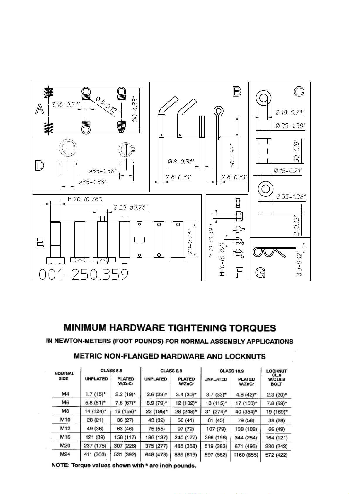
Assembly is correct when the various RH sections A, C, E, etc. and the various LH
sections B, D, F, etc. are aligned and parallel to each other and when the coupling
flanges G between one section and another are flush. NOTE: since these are sections
to be joined by means of welded flanges, there will not be perfect linearity between
RH sections A, C, E, etc. and LH sections B, D, F, thus a certain margin of error
must be tolerated. To reduce this error to a minimum, a few small techniques must
be used. For example, tighten the flange coupling bolts, one outside 1 and one inside
2, if the RH sections A, C, E, etc. and LH sections B, D, F, etc. are linear; or tighten
first the outside bolts 3-4 if the sections tend to curve toward the inside of the
machine, and vice versa tighten first the inside bolts 5-6 if the sections tend to curve
toward the outside.
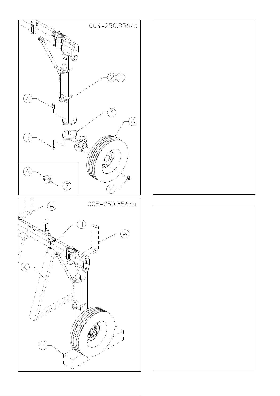
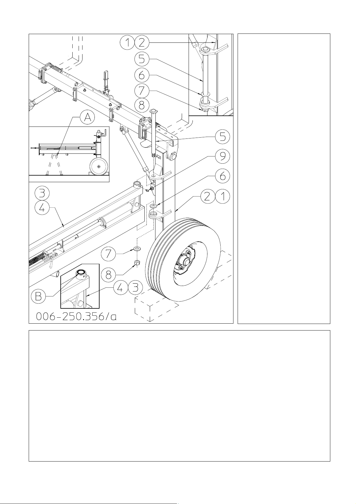
The alignment of the sections is important, as it also affects the assembly of the rake
wheel lifting pipes and how they slide along supports H during use. Bearing in mind
this advice, you can proceed with the assembly following the steps illustrated in
following. Unless otherwise specified, the assembly is shown for just one side of the
machine, but as it is symmetrical, simply repeat the same steps on the other side as
well. The quantities of the materials to be used for the various assembly steps refer
to both sides of the machine. The weights given near the major components may
vary by +/- 5%.
NOTE: What we are about to describe is an approximate assembly procedure. Each
person, based on their experience and on the tools they have to work with, may vary
the assembly steps to suit their needs. Always use great caution because the
assembly steps are dangerous.
5
6
1) DANGER
Insert bushings 4 in the openings in
supports 2-3 (RH/LH - 40kg/88lbs).
Lift unit 1 (weight 110kg/245lbs) with
asuitable forklift W. Connect the
vertical supports 2-3 to the crosspiece
assembly 1 using pin 5, washers 6-7
and bolt 8.
Insert the grease nipples 9 into the
openings in supports 2-3 and in the
crosspiece assembly 1.
In this step, you will use:
Item 4: 4 bushings ø50-60x50 (ø1.97”-
2.36”x1.97”)
Item 5: 2 pins ø50x190 (ø1.97”x7.5”)
Item 6: 2 spacers ø23-75x12 (ø0.91”-
2.95”x0.47”)
Item 7: 2 split washers ø23-35x4
(ø0.91”-1.38”x0.16”)
Item 8: 2 bolts M22x50 (0.87”x1.97”)
Item 9: 4 grease nipples M8 (0.32”)
2) DANGER
Work very carefully because the unit
assembled so far is very unstable. To
make sure that the supports 2-3 have
been attached correctly to unit 1,
check that the dimensions are those
given in the drawing at the side.
Note: The central holes A in the
lower flanges of supports 2-3 must
be on the inside.
7
3) DANGER
The tie rod 4 is preassembled to the right size for it to be attached to seat A on the
crosspiece assembly 1 and to seats C on the vertical supports 2-3. Part B of tie rod 4
goes to seat A on the crosspiece assembly 1 and part D goes to seat C on the vertical
supports 2-3. If a small adjustment must be made to adjust the length, loosen nut E,
rotate the head D until it reaches the right length, then lock in place with nut E. Connect
fork B on tie rod 4 to seat A on the crosspiece assembly 1 and part D of tie rod 4 to part
C of supports 2-3 using the pins 5, washers 6 and nuts 7.
In this step, you will use:
Item 5: 4 pins ø25x58 (ø1”x2.28”)
Item 6: 4 washers ø12-36x4 (ø0.47”- 1-42” x 0.16”)
Item 7: 4 nuts M12 (0.47”)
8
4) DANGER
Attach the wheel hubs 1 to vertical
supports 2-3 using bolts 4 and nuts
5. Attach the wheels 6 to the hubs 1
and fasten with the special nuts 7.
Note: the rounded part A of the
special nut 7 should be applied
facing the wheel 6.
In this step, you will use:
Item 4: 6 bolts M16x50
(0.63”x1.97”)
Item 5: 6 nuts M16 (0.63”)
Item 7: 10 special nuts M16x1.5
(0.63”)
5) DANGER
To continue with the assembly, unit
1must be stabilized. This can be
done either with a support K or
with a forklift W. Chocks H must
also be applied to the wheels.
Proceed with caution in the next
assembly steps, even with the unit
stabilized.
9
6) DANGER
Check that manufacturer
has assembled on the
vertical supports 1-2
(RH-LH) the pins 5,
spacers 6, washers 7 and
nuts 8 that you will use
for assembly in the
order in which you find
them assembled.
Check that manufacturer
has assembled the
bushings B to their seats
on sections 3-4 (RH-
LH).
Now attach sections 3-4
(RH-LH) to the seats on
the vertical supports 1-2
(RH-LH) using the pin
5, spacer 6, washers 7
and nuts 8.
Once sections 3-4 are
attached, set them on a
support A. Now apply
the grease nipples 9 to
the openings in sections
3-4.
6) DANGER
In this step, you will use:
Item 5: 2 pins ø35x450 (ø1.38”x17.72”)
Item 6: 2 spacers ø35-52x1.5 (ø1.38”-2.05”x 0.06”)
Item 7: 2 washers ø23-50x4 (ø0.91”-1.97”x 0.16”)
Item 8: 2 nuts M22 (0.87”)
Item 9: 2 grease nipples M8 (0.32”)
10
7) DANGER
Check that pipe B protrudes about 288mm-11.34” from section 1-2. Note: this
measurement is with the cylinder to which it is attached completely closed, and the total
pipe length must be 1670 mm – 65.75”.
Now attach sections 3-4 (RH-LH – 65kg/143lbs) to sections 1-2 (RH-LH) using bolts 5
and nuts 6.
Note: Once sections 3-4 are attached, move support A forward or use and additional
support.
In this step, you will use:
Item 5: 20 bolts M16x45 (0.63”x1.77”)
Item 6: 20 nuts M16 (0.63”)
11
8) DANGER
Now attach sections 3-4 (RH-LH – 105kg/230lbs) to sections 1-2 (RH-LH) using bolts 5 and
nuts 6.
In this step, you will use:
Item 5: 20 bolts M16x45 (0.63”x1.77”) - Item 6: 20 nuts M16 (0.63”)
9) DANGER
Insert the nylon bushings 5 into the openings in
sections 1-2 (RH-LH). Place spacer 4 on the pins
of the wheel units 3. Insert the wheel units 3 into
the openings in sections 1-2.
Attach the flange 6 onto the pins of the wheel
units 3 using the spring pins 7. Attach the grease
nipples 8 to the openings in sections 1-2.
Before continuing make sure that the wheel units
3can turn freely.
In this step, you will use:
Item 4: 2 spacers ø50-76x5 (1.97”x3”)
Item 5: 4 nylon bushings ø50-60x50 (ø1.97”-
2.36x1.97”)
Item 7: 2 spring pins ø10x80 (0.4”x3.15”)
Item 8: 2 grease nipples M8 (0.31”)
12
10) DANGER
Attach the plate with bolt 2
underneath flange 1. Attach the
counterplate 3 over flange 1,
inserting the counterplate pins A
into the holes in the plate with bolt
2and into holes B in the sections.
Place the bushing 4, spring 5 and
washer 6 over the plate 2 bolt and
put nut 7 on the bolt.
Note: the more spring 5 is
compressed by tightening nut 7, the
more the turning of the wheel is
braked, therefore check that it is
adjusted properly when the
machine is to be operated (see
machine use).
In this step, you will use:
Item 4: 2 bushings ø13-18x20
(0.5”-0.71”x0.79”)
Item 5: 2 springs ø5-30x45
(0.20”-1.18”x1.77”)
Item 6: 2 washers ø12-36x4
(ø0.47”-1.42x0.16”)
Item 7: 2 nuts M12 (0.47”)
11)
You have now reached this stage
of the assembly. The machine
rests on its wheels and thus has
good stability. However, continue
to use great caution during the
rest of the assembly, so as to work
safely. In order to work better,
spread apart the right and left
sections of the machine.
13
12)DANGER
Note: Sections 3-4 (RH-LH) are to be assembled only for MK/16.
Attach sections 3-4 (RH-LH) to sections 1-2 (RH-LH) using bolts 5 and nuts 6.
Note: For MK/14 and MK/16 – At this point the assembly of the sections is
completed. Apply the grease nipples 7 to all the bushings A on all the RH and LH
sections.
In this step, you will use:
Item 5: 12 bolts M16x45 (0.63”x1.77”) (MK/16 only)
Item 6: 12 nuts M16 (0.63”) (MK/16 only)
Item 7: 14 (MK/14) 16 (MK/16) grease nipples M6x45° (0.23”x45°)
14
13) DANGER
Attach the wheel supports 3-4 to sections 1-2
(RH-LH) using bolts 5 and nuts 6.
Apply grease nipples 7 to the seats in wheel
supports 3-4.
In this step, you will use:
Item 5: 12 bolts M16x45 (0.63”x1.77”)
Item 6: 12 nuts M16 (0.63”)
Item 7: 2 grease nipples M8 (0.31”)
14) DANGER
Insert the nylon bushings 5 into the openings
in support 1-2 (RH-LH). Place spacer 4 on
the pins of the wheel units 3. Insert the
wheel units 3 into the openings in sections 1-
2. Attach the flange 6 onto the pins of the
wheel units 3 using the spring pin 7.
Before continuing make sure that the wheel
units 3 can turn freely.
Attach the plate with bolt 8 underneath
flange 6. Attach the counterplate 9 over
flange 6, inserting the counterplate pins A
into the holes in the plate with bolt 8 and
into holes B in the supports 1-2. Place the
bushing 10, spring 11 and washer 12 over
the plate 8 bolt and put nut 13 on the bolt.
Note: the more spring 11 is compressed by
tightening nut 13, the more the turning of the
wheel is braked, therefore check that it is
adjusted properly when the machine is to be
operated (see machine use).
14) DANGER
In this step, you will use:
Item 4: 2 spacers ø50-76x5 (1.97”x3”)
Item 5: 4 nylon bushings ø50-60x50 (ø1.97”-2.36x1.97”)
Item 7: 2 spring pins ø10x80 (0.4”x3.15”)
Item 10: 2 bushings ø13-18x20 (0.5”-0.71”x0.79”)
Item 11: 2 springs ø5-30x45 (0.20”-1.18”x1.77”)
Item 12: 2 washers ø12-36x4 (ø0.47”-1.42x0.16”)
Item 13: 2 nuts M12 (0.47”)
15
15) DANGER
Check to make sure the manufacturer has correctly secured the bushings C with
retaining rings D on all the RH and LH sections.
In this assembly position holes F in pipes 1-3 are not used.
Starting from bracket A for the 16-rake wheel machine and from bracket B for the
14-rake wheel machine, insert pipe 1 (L.2515mm-99.01”) into all the brackets B until
reaching pipe E already assembled by the manufacturer. Join pipe 1 to pipe E using pin
4, bolts 5 and nuts 6.
Now, starting from bracket A for the 16-rake wheel machine, insert pipe 2
(L.2415mm-95.07”) into all the brackets B until reaching pipe 1. Join pipe 2 to pipe 1
using pin 4, bolts 5 and nuts 6.
Now, starting from bracket B for the 14-rake wheel machine, insert pipe 3
(L.1670mm-65.75”) into all the brackets B until reaching pipe 1. Join pipe 3 to pipe 1
using pin 4, bolts 5 and nuts 6.
In this step, you will use:
Item 4: 4 pins ø25-35x158 (ø1”-1.38”x6.22”)
Item 5: 8 bolts M8x45 (0.31” x1.77”)
Item 6: 8 nuts M8 (0.31”)
16
16) DANGER
Carry out this operation very
carefully and with suitable lifting
equipment because the drawbar 2
is heavy and bulky. Weight
170kg/375lbs. First of all remove
the nut A and packing retainer B
from the crosspiece assembly 1.
The nuts A and packing retainers
Bwill not be reused. To work
safely and make the next
assembly easier, set the drawbar
27 on a support C.
Attach the drawbar 2 to the
counterplate 3 using bolts 4 and
nuts 5.
In this step, you will use:
Item 4: 8 bolts M16x165
(0.63”x6.5”)
Item 5: 8 nuts M16 (0.63”)
17) DANGER
Carry out this operation very
carefully and with suitable
lifting equipment because the
drawbar 2 is heavy and bulky.
Weight 150kg/330lbs plus the
preceding drawbar.
To work safely and make the
next assembly easier, set the
drawbar 2 on a support B.
Attach drawbar 2 to drawbar 1
using bolts 3 and nuts 4.
17) DANGER
In this step, you will use:
Item 3: 12 bolts M16x45 (0.63”x1.77”)
Item 4: 12 nuts M16 (0.63”)
17
19) DANGER
Carry out this operation very carefully and
with suitable lifting equipment because the
drawbar 2 is heavy and bulky. Weight
60kg/132lbs plus the preceding drawbars.
First of all check to make sure the
manufacturer has applied the bushings for the
safety arms on seat B.
Now attach drawbar 2 to drawbar 1 using
bolts 3 and nuts 4.
Attach the stand 5 to seat C on drawbar 2
using the pin 6 and clip 7.
Note: for the transport position of the stand,
see machine use.
Attach the tractor hitch to the two + two
central holes of the bracket on drawbar 2
using pins 9, washers 10 and bolts 11.
Note: the correct position of the pins 9 is that
shown in the drawing.
In this step, you will use:
Item 3: 8 bolts M16x45 (0.63”x1.77”)
Item 4: 8 nuts M16 (0.63”)
Item 6: 1 pin ø15x78 (ø0.59x3.07”)
Item 7: 1 clip ø3 (ø0.12”)
Item 9: 2 pins ø25x124 (0.98”x4.88”)
Item 10: 2 washers ø12-36x4 (0.94”)
Item 11: 2 bolts M12x20 (0.47x0.79”)
18) DANGER
Carry out this operation very
carefully and with suitable
lifting equipment because the
drawbar 2 is heavy and bulky.
Weight 135kg/297lbs plus the
preceding drawbar.
To work safely and make the
next assembly easier, set the
drawbar 2 on a support A.
Attach drawbar 2 to drawbar 1
using bolts 3 and nuts 4.
18) DANGER
In this step, you will use:
Item 3: 10 bolts M16x45 (0.63”x1.77”)
Item 4: 10 nuts M16 (0.63”)
18
21) DANGER
The safety arms 1 are made up of an
inner part A and an outer part B
assembled together by the
manufacturer using the pin and clip
C(same as pins 4 and clips 5). In
addition, in the fork of the inner part
Ayou will find preassembled by the
manufacturer the pin 4 and clip 5,
whereas on the fork of the outer part
Byou will find preassembled the
bolt 2 and nut 3. You will need
these to attach the safety arms to
seats D-E on the drawbar. Attach
safety arm 1 to seat D on the
drawbar and fasten in place with
bolt 2 and nut 3.
Attach the other end of safety arm 1
to seat E on the drawbar and fasten
in place with pin 4 and clip 5.
21) DANGER
In this step, you will use:
Item 2: 2 bolts M16x90 (0.63”x3.54”) - Item 3: 2 nuts M16 (0.63”)
Item 4: 2 (4) pins ø15x78 (ø0.59x3.07”) - Item 5: 2 (4) clips ø3 (ø0.12”)
20) DANGER
Attach the safety chain 1 to the
holes A in the drawbar using the
bolt 2, washer 3 and nut 4.
Attach the canister 5 to seats B on
the drawbar using bolts 6, washers 7
and nuts 8.
In this step, you will use:
Item 2: 1 bolt M22x150
(0.87”x5.91”)
Item 3: 1 split washer ø23 (ø0.91”)
Item 4: 1 nut M22 (0.87”)
Item 6: 3 bolts M6x20
(ø0.24x0.79”)
Item 7: 6 washers 6.6-18x2
(ø0.26”-0.71”x0.08”)
Item 8: 3 nuts M6 (0.24”)
19
23)
You have now reached this stage of the
assembly. The machine rests on its wheels
and the stand and thus has good stability.
However, continue the assembly using great
caution so as to work safely.
22) DANGER
In this step, you will use:
Item 6: 16 bolts M14x140 (0.55”x5.51”) Item 7: 16 nuts M14 (0.55”)
22) DANGER
Attach the opening
arms 3-4 (RH-LH)
to sections 1-2 by
means of the
counterplates 5,
bolts 6 and nuts 7.
In box A the
theoretic
measurements are
given for the
assembly of arms 3-
4and counterplates
5. At this stage do
not fully tighten nuts
7, because when the
cylinders are
attached (see step
27) it may be
necessary to move
the arms 3-4 and
counterplates 5
slightly forward or
backward to allow
the correct
installation of the
cylinders.
20
25) DANGER
(see next page)
Note: for logical sequence purposes we describe the assembly of the rake wheels to the
machine frame, but given their bulkiness, if you wish to work with more room available
skip ahead to the assembly of the hydraulic system and then come back to the assembly
of the rake wheels.
First insert the nylon bushings 1 in the all the seats A in all the sections (RH-LH). Next
insert the rake wheel arms 2-3 (RH-LH) in all the seats A in all the sections and secure in
place with the washers 4 and spring pins 5. Attach the rake wheels 6-7 (RH-LH) to the
arms 2-3 using the bolts 8, washers 9 and nuts 10.
Note: Either 55” or 60” rake wheels can be put on the machine using the same procedures
and same components.
24) DANGER
Insert brackets 2 in the slots A in all the pipes (RH-LH). Attach the chain 3 at all the
brackets 2 using the bolt, washer 5 and nut 6.
In this step, you will use:
Item 2: 14-16 chain brackets - Item 3: 14-16 chains, length 820mm (32.3”) Item 4:
14-16 bolts M10x25 (0.4”x1”) - Item 5: 14-16 washers ø11-30x2.5 (ø0.43”-1.18”x0.1”) -
Item 6: 14
-
16 nuts M10 (0.4”)

This manual suits for next models

1

Other sitrex Farm Equipment manuals

sitrex MX 12 Quick setup guide

sitrex

sitrex MX 12 Quick setup guide

sitrex DM/6 Guide

sitrex

sitrex DM/6 Guide

sitrex GS 160 User guide

sitrex

sitrex GS 160 User guide

sitrex TR/11 Quick setup guide

sitrex

sitrex TR/11 Quick setup guide

sitrex SM 3600 Quick setup guide

sitrex

sitrex SM 3600 Quick setup guide

sitrex RT/5800-H Quick setup guide

sitrex

sitrex RT/5800-H Quick setup guide

sitrex BR 2030/6 User manual

sitrex

sitrex BR 2030/6 User manual

sitrex MKE/18-20 User manual

sitrex

sitrex MKE/18-20 User manual

sitrex SR 320/8 User guide

sitrex

sitrex SR 320/8 User guide

sitrex DM/4 Guide

sitrex

sitrex DM/4 Guide

sitrex BR 2030/6 User manual

sitrex

sitrex BR 2030/6 User manual

sitrex SM/230 Assembly instructions

sitrex

sitrex SM/230 Assembly instructions

sitrex M 60 MINI/S User manual

sitrex

sitrex M 60 MINI/S User manual

sitrex Action 120 User manual

sitrex

sitrex Action 120 User manual

sitrex MKE/14-16 User manual

sitrex

sitrex MKE/14-16 User manual

sitrex HM 360 Quick setup guide

sitrex

sitrex HM 360 Quick setup guide

sitrex RP/4 Guide

sitrex

sitrex RP/4 Guide

sitrex QRX 12 Quick setup guide

sitrex

sitrex QRX 12 Quick setup guide

sitrex 250.799 User manual

sitrex

sitrex 250.799 User manual

sitrex TR/6-S Quick setup guide

sitrex

sitrex TR/6-S Quick setup guide

sitrex SB150 Quick setup guide

sitrex

sitrex SB150 Quick setup guide

sitrex RT/5200 Quick setup guide

sitrex

sitrex RT/5200 Quick setup guide

sitrex SR 420/11 H Guide

sitrex

sitrex SR 420/11 H Guide

sitrex MX 8 Quick setup guide

sitrex

sitrex MX 8 Quick setup guide

Popular Farm Equipment manuals by other brands

Tatu Marchesan PMT Operator's manual

Tatu Marchesan

Tatu Marchesan PMT Operator's manual

PRONAR PT512 Operator's manual

PRONAR

PRONAR PT512 Operator's manual

WIL-RICH 2550 Operator's manual

WIL-RICH

WIL-RICH 2550 Operator's manual

CONCORD PRECISION SHANK DRILL Assembly manual

CONCORD

CONCORD PRECISION SHANK DRILL Assembly manual

TKS FeedBelt Operator's manual

TKS

TKS FeedBelt Operator's manual

Monosem MS manual

Monosem

Monosem MS manual

Sly France BOSS Series operating instructions

Sly France

Sly France BOSS Series operating instructions

H&S HDNR 7+4 Operator's manual / parts book

H&S

H&S HDNR 7+4 Operator's manual / parts book

DALBO MAXIROLL 950 manual

DALBO

DALBO MAXIROLL 950 manual

Avantco A37064 Operator's manual

Avantco

Avantco A37064 Operator's manual

GREAT PLAINS VT1520-0370 Operator's manual

GREAT PLAINS

GREAT PLAINS VT1520-0370 Operator's manual

Redexim 7117 user manual

Redexim

Redexim 7117 user manual

Buhler Farm King Grain Vac Conveyair 6640 Operator and parts manual

Buhler

Buhler Farm King Grain Vac Conveyair 6640 Operator and parts manual

Degelman PRO-TILL 30 quick start guide

Degelman

Degelman PRO-TILL 30 quick start guide

Farm King 1450 Operator and parts manual

Farm King

Farm King 1450 Operator and parts manual

KUHN HR4004D Operator's manual

KUHN

KUHN HR4004D Operator's manual

Duncan Enviro DD35 owner's manual

Duncan

Duncan Enviro DD35 owner's manual

Gude GGF 620 Translation of the original instructions

Gude

Gude GGF 620 Translation of the original instructions

manuals.online logo
manuals.online logoBrands
  • About & Mission
  • Contact us
  • Privacy Policy
  • Terms and Conditions

Copyright 2025 Manuals.Online. All Rights Reserved.