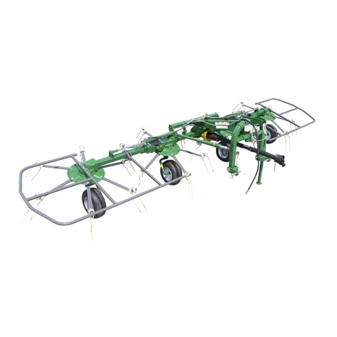
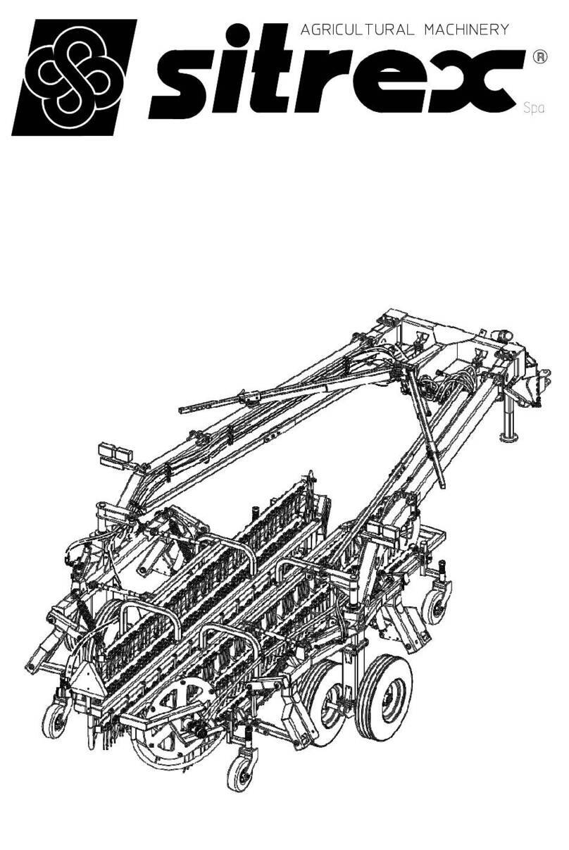
sitrex TR/11 Quick setup guide

ASSEMBLY,
USE AND MAINTENANCE
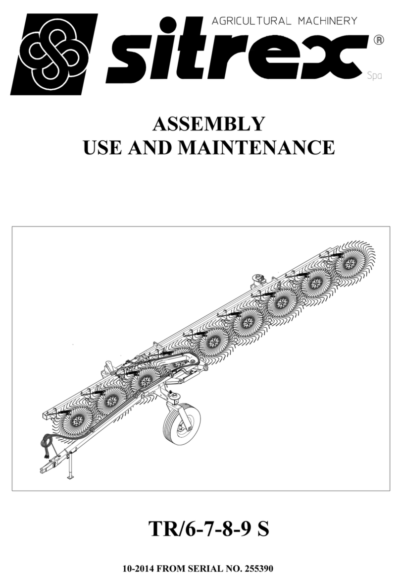
HAY RAKE, PULL TYPE
TR/11-13 S

1
Introduction
This manual includes full instructions for the correct use and maintenance of the
machinery, and also the recommended spare parts list.
In order to prevent any possible damage or injury to the machine and/or the operator(s),
read this manual carefully for proper knowledge of the assembly of the implements, their
use in the field, and their maintenance. If you have any doubts, please contact your local
dealer or distributor.
Should the machine be resold, please supply this manual along with the machine to the
new purchaser.
Warranty
The manufacturer warrants new machinery to be free from defects in materials and
workmanship at the time of delivery to the original purchaser if correctly set up and
operated according to this Operator's Manual.
The manufacturer will repair or replace free of charge any defective part which is returned
by the purchaser (freight prepaid) and found to be defective on inspection authorized by
the manufacturer during the warranty period.
This warranty shall be valid for 12 (twelve) months from the delivery of the goods to the
original purchaser.
If the customer is unable to return the defective part to the manufacturer, the manufacturer
cannot be held liable for any costs due for repair or replacement of any part of the
machine. The manufacturer shall only supply the part(s) required for such repair and/or
replacement.
The warranty shall be considered null and void when it is evident that the machine has
been improperly used or has been repaired without authorization.
The manufacturer shall not be held liable for any obligation or agreement reached by any
employers, agents or dealers who do not comply with the above warranty. The
manufacturer cannot be held liable for the subsequent damages. This warranty replaces
any other warranty, either explicit or implied, as well as any other obligation of the
manufacturer.
NOTE:
ALL WARRANTY WORK OR REPAIRS MUST BE APPROVED BY THE
MANUFACTURER BEFORE WORK BEGINS. ANY WORK OR REPAIRS MADE
BEFORE APPROVAL MAY NOT BE COVERED UNDER WARRANTY.
PLEASE NOTIFY YOUR SALES & SERVICE DEPARTMENT OF THIS POLICY.
TABLE OF CONTENTS:
1) GENERAL INSTRUCTIONS
2) GUIDE TO THE SIGNS AND SYMBOLS
3) PRODUCT IDENTIFICATION
4) DELIVERY AND ASSEMBLY INSTRUCTIONS
5) INSTRUCTIONS FOR WORK AND TRANSPORT
6) GENERAL MAINTENANCE INSTRUCTIONS

2
1)General instructions for operation and maintenance
Read all the directions carefully before using the machine. When in doubt,
seek advice from the manufacturers. The manufacturing company declines all
liability for non-compliance with the following safety and accident-prevention
instructions.
1- Pay attention to the danger signs and symbols in this manual and on the machine.
2- Do not touch moving parts.
3- All work on the machine (including adjustments) must always be carried out with the
tractor immobilized and the engine switched off.
4- It is strictly prohibited to carry persons or objects on the machine and/or on the tractor.
5- Driving the tractor with the machine connected is absolutely forbidden to persons
lacking suitable experience, or who are in poor health, or who do not have a suitable
driving license.
6- All accident-prevention measures recommended in this manual should be strictly
followed.
7- When a machine is attached to the tractor, always evaluate the suitability of the tractor
for the purpose, in order to work safely. Keep in mind that when a machine is attached
to the tractor – even if it is a towed type – it alters the tractor’s stability, and therefore all
the necessary precautions must be taken (ballast, tire pressure, etc.).
8- Before operating the tractor and machine, check that all transport and operational
safety devices are complete and working.
9- When driving on public roads, you should comply with the Highway Code regulations
for the country concerned.
10-Before starting work, familiarize yourself with the control devices and how they work.
11-Wear suitable clothes. Do not wear clothing which is loose or which could become
entangled in rotating or moving parts.
12-Never leave the driving seat when the tractor is running.
13-It is extremely important to appreciate that road holding, steering and braking may be
significantly affected with the machine attached.
14-Before connecting the unit, stop the engine, apply the parking brake and remove the
ignition key from the instrument panel.
15-Spare parts must meet the requirements as defined by the manufacturer. Use only
original spare parts.
16-Safety decals must always be clearly visible. They must be kept clean and replaced if
they become too illegible (they can be ordered from the agent if necessary).
3
2) Guide to the signs and symbols used on the machine
IMPORTANT
These signs and symbols give information to the operator on how to make the best use of
the machine so as to prolong its life, avoid damage, optimize work and, above all, to avoid
injury to the operator and anyone within range of the machine. Note: most of the symbols
that you will find below are located on the machine, but some are only in this manual and
indicate how to act or what must be done during assembly, when maintenance or repairs
are being done, etc..
1) Before beginning operations, read the instruction
manual carefully.
2) Before doing any maintenance or repair work, stop the
machine at a suitable spot. Turn off the tractor motor, apply
the brake, remove the key from the ignition and consult this
manual.
3) This is a warning to wear proper personal protective
equipment when carrying out maintenance and repairs

4
4) Risk of possible ejection of blunt objects. Keep a
safe distance from the machine
5) Indicates that there is a risk of crushing your hands.
Keep your distance.
6) Indicates a greasing point.

5
Examples of general measurements for identifying the assembly
accessories based on type.
When tightening the bolts refer to the tightening torque table (the class of the
material is generally stamped on the head of the bolts).

6
3) Product identification
Please write below the type and
serial number of the machine.
This information is to be
provided to the dealer for all
spare parts orders.
MACHINE SPECIFICATIONS
1DRAWBAR 9 TIE ROD
2PARKING STAND 10 ARM
3SUPPORT 11 ARM
4TIE ROD 12 FRONT ARM
5WHEEL ASSY. 13 REAR ARM
6CYLINDERS 14 SECTION
7TIE ROD 15 RAKE WHEEL ASSY.
8SUPPORT 16 HYDRAULIC KIT

7
TECHNICAL SPECIFICATIONS
MODELS TR/11 TR/13
Weight 1400 Kg / 3100 lb 1500 Kg / 3300 lb
Overall length (A) 10.3 m / 33’8” 12.8 m / 42’
Transport height (B) 1.750 m / 68.9” 1.750 m / 68.9”
Transport width (C) 2.48 m / 97.6” 2.48 m / 97.6”
Number of rake wheels 11 13
Number of tines on each rake wheel 40 40
Tines diam. 7.5mm / 0.3” 7.5mm / 0.3”
Wheel diam. 1.4 m. / 55’’ 1.4 m. / 55’’
Raking working width 6.5 m. / 21’ 3’’ 7.5 m. / 24’ 7’’
Working speed 22 kmh / 14 mph 22 kmh / 14 mph
HP required min. 35 HP / 26 kW 35 HP / 26 kW

8
4) Delivery and assembly
Delivery and unpacking
The machine is delivered partially assembled in 1 (one) box containing 6 (six) boxes and 1
(one) pallet. The boxes "A", "B", “C”, ”D”, ”E”, and “F” are all the various mounting
accessories (pins, screws, fittings, etc..) All components are inspected by the
manufacturer before shipment. Upon receipt of the machine, ensure that the case is intact
and that the contents have not been damaged during transport. If you detect damage and
/or anomalies immediately report the matter to your vendor.
Note: The packaging is made from wood, plastic film, cardboard and steel, and must
be disposed of according to applicable laws in your locality.
To unpack the boxes received by using suitable lifting is to lift the weight
given to the banks to bring stability to the pallets because of their size and shape.
Each machine arrives packed in one crate and one pallet

9
Assembly instructions
Assembly must be done carefully and accurately, for the safety of the person(s)
doing the assembling and to ensure proper machine operation.
Assembly should be done on a flat, solid surface, using the proper tools and
wearing suitable clothing, making sure that all people not involved in the assembly
are kept at a safe distance. Assemblers must provide suitable lifting mechanisms
and supports for stabilizing the partially assembled units, so as to prevent them
from falling and causing damage or injury. The steps for assembly are illustrated in
following. Depending on the experience of the assemblers and the tools available, it
is not necessary that the instructions be followed in the exact order given here, but
the safety precautions described above must always be strictly and carefully
followed.
ATTENTION

10
Step 1
Step 1
Set sections 1 and 2 on supports A, then connect the two sections using bolts 3
and nuts 4.
(If you do not have supports, the assembly can also be done on the ground.)
In this step use the following parts:
Position 3: 8 bolts M16x45 (0.63”x1.77”)
Position 4: 8 nuts M16 (0.63”)

11
Step 2
Step 2
Before attaching the wheel assembly 2, brush pin B and pin 6 with grease.
Insert nylon bushings 4 in the seats as shown. Place the shim 3 over the pins of the wheel
assemblies 2.
Insert the preassembled wheel assemblies 2 into the seats in section 1.
Attach the flange 5 to the pin on wheel assemblies 2 using the spring pin 6.
Attach the grease nipples 12 to the seats in section 1.
Check to make sure that the wheel assemblies 2 turn freely in the seats in section 1.
Attach the plate with screw 7 underneath flange 5.
Attach the counterplate 8 over the flange 5, inserting its pins into the holes in plate with screw 7
and in section 1.
Attach the spring 9, washer 10 and nut 11 to the screw on plate 7.
IMPORTANT:
The more spring 4 is compressed by tightening nut 11, the more the wheel rotation is braked,
therefore check that it is properly adjusted before using the machine.
In this step use the following parts:
Position 3: 2 shims ø50-76x5 (1.97”x3”)
Position 4: 4 nylon bushings ø50-60x50 (1.97”-2.36”x1.97”)
Position 6: 2 spring pins ø10x80 (0.4”x3.15”)
Position 9: 2 springs ø5-30x45 (0.20”-1.42”x0.1”)
Position 10: 2 washers ø12-36x2.5 (0.47”-1.42”x0.1”)
Position 11: 2 nuts (0.47”)
Position 12: 2 grease nipples M8

12
Step 3
Step 3
Attach arm 2 to section 1 between lugs B and C, using plates 3 bolts 4 and nuts 5.
In this step use the following parts:
Position 4: 8 bolts M14x140
Position 5: 8 nuts M14

13
Step 4
Step 4
With the section resting on supports A and kept in balance with a belt attached to
the forks of the forklift C, attach the swiveling arm 2 to arm B, first placing shims 3
between the two plates, then pin 4, washer 5, bolt 6, washer 7 and nut 8.
Insert grease nipple 9 into the seat on arm 2.
In this step use the following parts:
Position 3: 2 shims ø75-100x1
Position 4: 1 pin ø75x127
Position 5: 1 washer ø25-64x10
Position 6: 1 bolt M24X180
Position 7: 1 washer ø25-90x10
Position 8: 1 nut M24
Position 9: 1 grease nipple M8

14
Step 5
Step 5
Keeping the machine in balance with a belt attached to arm 2 and to the forks of the
forklift A, attach arm 1 to arm 2 with bolts 3 and nuts 4.
In this step use the following parts:
Position 3: 8 bolts M14x45
Position 4: 8 nuts M14

15
Step 6
Step 6
Before attaching the wheel assembly 2, brush pin B and pin 6 with grease.
Keeping the machine in balance with a belt attached to the forks of the forklift A, insert nylon
bushings 4 in the seats in arm 1. Place the spacer 3 over the pin of the wheel assembly 2.
Insert the preassembled wheel assembly 2 into the seat in section 1.
Attach the flange 5 to the pin on wheel assembly 2 using the spring pin 6.
Attach the grease nipples 12 to the seats in section 1.
Check to make sure that the wheel assembly 2 turns freely in the seat in arm 1.
Attach the plate with screw 7 underneath flange 5.
Attach the counterplate 8 over the flange 5, inserting its pins into the holes in plate with screw 7
and in arm 1.
Attach the spring 9, washer 10 and nut 11 to the screw on plate 7.
IMPORTANT:
The more spring 4 is compressed by tightening nut 11, the more the wheel rotation is braked,
therefore check that it is properly adjusted before using the machine.
In this step use the following parts:
Position 3: 1 shim ø50-76x5 (1.97”x3”)
Position 4: 2 nylon bushings ø50-60x50 (1.97”-2.36”x1.97”)
Position 6: 1 spring pin ø10x80 (0.4”x3.15”)
Position 9: 1 spring ø5-30x45 (0.20”-1.42”x0.1”)
Position 10: 1 washer ø12-36x2.5 (0.47”-1.42”x0.1”)
Position 11: 1 nut (0.47”)
Position 12: 2 grease nipples M8

16
Step 7
Step 7
Fasten the swivel attachment section 1 to section 2 using bolts 3 and nuts 4.
Insert the nylon bushings 5 in the seats as shown.
Attach the grease nipple 6 to the seat in support 1.
IMPORTANT
Insert the bolts and nuts as shown in the drawing – do not reverse the positions for
reasons of space.
In this step use the following parts:
Position 3: 8 bolts M16x45 (0.63”x1.77”)
Position 4: 8 nuts M16 (0.63”)
Position 5: 2 nylon bushings ø50-60x50 (1.97”-2.36”x1.97”)
Position 6: 1 grease nipple M8x45°

17
Step 8
Step 8
Attach rear arm 2 to section 1 within the spaces indicated with adhesive, using
counterplates 3, bolts 4 and nuts 5.
IMPORTANT
In order to facilitate the assembly of the next components, do not fully tighten the
bolts.
In this step use the following parts:
Position 4: 8 bolts M14x140
Position 5: 8 nuts M14

18
Step 9
Step 9
Attach the rear swiveling arm 2 to arm 1, first inserting the shims 3 between the two
plates on arm 1, then assemble the pin 4, washer 5, bolt 6, washer 7 and nut 8.
Attach the grease nipple 9 to the seat in arm 2.
In this step use the following parts:
Position 3: 2 shims ø75-100x1
Position 4: 1 pin ø75x127
Position 5: 1 washer ø25-64x10
Position 6: 1 bolt M24X180
Position 7: 1 washer ø25-90x10
Position 8: 1 nut M24
Position 9: 1 grease nipple M8

19
Step 10
Step 10
Before attaching the wheel assembly 2, brush pin A and pin 6 with grease.
Insert nylon bushings 4 in the seats in arm 1. Place the shim 3 over the pin of the
wheel assembly 2.
Insert the preassembled wheel assembly 2 into the seat in arm 1.
Attach the connecting rod 5 to the pin on wheel assembly 2 using the spring pin 6.
Attach the grease nipple 7 to the seat in arm 1.
Check to make sure that the wheel assembly 2 turns freely in the seat in arm 1.
In this step use the following parts:
Position 3: 1 shim ø50-76x5 (1.97”x3”)
Position 4: 2 nylon bushings ø50-60x50 (1.97”-2.36”x1.97”)
Position 6: 1 spring pin ø10x80 (0.4”x3.15”)
Position 7: 1 grease nipple M8
Note:
At this point, for reasons of space, it is recommended that you proceed by
mounting the rake wheels.
This manual suits for next models
1
Table of contents
Other sitrex Farm Equipment manuals

sitrex
sitrex Action 120 User manual

sitrex
sitrex MKE/18-20 User manual

sitrex
sitrex MX 8 Quick setup guide

sitrex
sitrex SR 320/8 H Guide

sitrex
sitrex HM 360 Quick setup guide

sitrex
sitrex MK14 MY15 User manual

sitrex
sitrex RT/5800-H Quick setup guide

sitrex
sitrex QRX 12 Quick setup guide

sitrex
sitrex TR/6-S Quick setup guide

sitrex
sitrex RT/5200 Quick setup guide

sitrex
sitrex M 60 MINI/S User manual

sitrex
sitrex BR 2030/6 User manual

sitrex
sitrex MKE/14-16 User manual

sitrex
sitrex DM/4 Guide

sitrex
sitrex DM/6 Guide

sitrex
sitrex GS 160 User guide

sitrex
sitrex 250.799 User manual

sitrex
sitrex BR 2030/6 User manual

sitrex
sitrex MX 12 Quick setup guide

sitrex
sitrex RP/4 Guide