sitrex SB150 Quick setup guide

ASSEMBLY,
USE AND MAINTENANCE
SPARE PARTS LIST
SB/150 - SB/165
SB/180 – SB/210
10


WARRANTY
1
DEAR CUSTOMER,
WE WOULD LIKE TO WELCOME YOU AS OUR-PRODUCT USER AND THANK YOU FOR
CHOOSING OUR MACHINE.
OUR MACHINES ARE THE RESULT OF CAREFUL STUDY AND YEARS OF EXPERIENCE.
WE HAVE ALWAYS PLACED IMPROVEMENT AMONG OUR PRIME OBJECTIVES.
WE WOULD LIKE TO POINT OUT, HOWEVER, THAT FOR LASTING PROTECTION OF THE
CAPITAL YOU HAVE INVESTED, IT IS NECESSARY TO FOLLOW THE INSTRUCTIONS IN
THIS BOOKLET WHICH ILLUSTRATES THE CHARACTERISTICS, THE OPERATION AND
THE MAINTENANCE OF THE MACHINE IN DETAIL.
THE CONTENTS OF THIS BOOKLET ARE INTENDED TO BE A GUIDE, THE
MANUFACTURER RESERVES THE RIGHT TO MODIFY THE SPECIFICATIONS OF THE
MACHINE WITHOUT BEING OBLIGED TO IMMEDIATELY UP-DATE THIS BOOKLET.
WARNING
BEFORE STARTING THE MOWING OPERATIONS ALWAYS CHECK THAT ALL THE
CONNECTIONS ARE THOROUGHLY TIGHTENED.
THE MOWER MUST NEVER BE OPERATED WHILE ANYONE IS WITHIN RANGE OF THE
MACHINE.
THE MANUFACTURER DECLINE EVERY RESPONSIBILITY FOR EVENTUAL ACCIDENTS
SHOULD HAPPENED AFTER A WRONG OR BAD USE OF THE MACHINE.

ASSEMBLY, USE AND MAINTENANCE
2
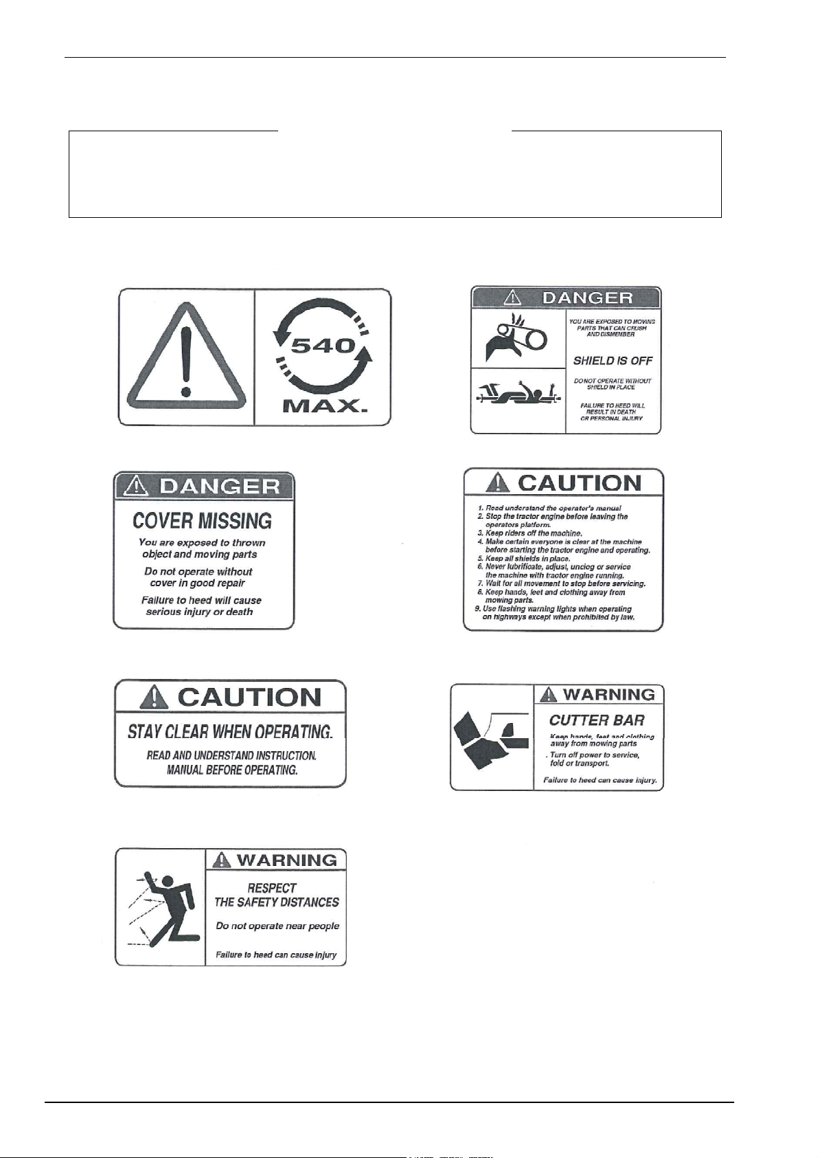
SAFETY INFORMATION & WARNING
Always read your operators manual thoroughly before operating or performing any
maintenance on your mower. Before you operate this machine, know your controls and how to
stop the tractor and mower quickly in an emergency! Read and observe all safety decals on the
tractor and mower.
Use extreme caution and reduce speed when operating on hillside. Use cabs equipped with
ROPS (Roll Over Protection) and seat belts. Mowers are more likely to throw objects when
operating on hillside and tractors can easily tip. Either could result in serious injury to operator.
Never start or stop suddenly when going up or downhill. This could result in tipping of the tractor
or a roll-over. If steep slopes are anticipated, adjust the wheel width, add fluid to tires or add
tractor weights to compensate. Avoid steep slopes. Do not raise the cutter bar when mowing
hillsides. Doing so may increase the likelihood of tipping.
Only the operator should ride on the tractor no one should ride on the mower. Persons riding on
the tractor or the mower could easily fall into the path of the machine resulting in serious injury.
Anyone operating this machine must be instructed in the operation and capable of safe operation
of the unit. Never allow children to operate this machine!
Never use drugs or alcoholic beverages which can hinder alertness or coordination while
operating. Consult your doctor about operating this machine while taking prescription drugs.
Always keep all covers, blades and guards, furnished with the machine, in place and in good
condition. Failure to do so could result in the operator being struck by high speed cutter bar. Keep
clear all mowing parts.
Make sure all onlookers personnel, children and pets are out of the area to be mowed. Make sure
pets and small children are not under or around the machine when you start the mower.
Always wear proper foot protection. Never operate the mower in bare feet or while wearing
sandals or sneakers.
Always operate in daylight conditions or use sufficient artificial lighting. Use extreme caution when
mowing under conditions which could hinder your ability to see people, pets or obstructions in the
mowing area.
Always check the drive line connections at the tractor and the gearbox before operation of the
mower. Be sure the quick disconnects are locked before operation.
Always disengage the tractor PTO and shift into neutral before starting the tractor.
Always lower the mower to the ground and shut off the tractor before dismounting and be sure
that the mowing motion has stopped
Failure to do so could result in the operator being injured by mowing tractor, mower or driveline
parts.
WARNING !!!

ASSEMBLY, USE AND MAINTENANCE
3
Always stop the tractor's engine and disengage the PTO before making adjustments or cleaning
the mower.
Always disengage the driveline and block up the machine before performing maintenance on the
mower.
Never operate the mower while in the raised of the transport position.
Avoid sharp turns while mowing. Remember that a 3-point mounted mower will swing in a wide
arc when the tractor is turned. Allow sufficient clearance for the mower when turning.
Always stop the mower and tractor upon hitting an obstruction. Stop the tractor engine and
inspect the mower before resuming operation.
Observe minimum and maximum PTO RPM limits. Failure to do so could result in damage to
equipment. Use only 540 RPM.
When transporting the mower on public roads, always use the tractor's safety warning lights and
slow mowing vehicle emblem. Consult local regulations about the use of additional lights or
flashers.
Perform preventive maintenance on a regular basis. Replace worn or damaged parts immediately.
Keep all nuts and bolts tight at all times. Failure to do so could result in serious injury to personnel
or machinery. Make sure all safety decals are in place and visible. Replace decals immediately
when they become illegible.
Do not use this machine in extremely rocky field conditions.
Never operate the mower with cutter bar locked in the UP position or any time the cutter bar
locked in the UP position or any time the cutter bar is raised. Never allow anyone near the cutter
bar when the tractor is running.
Always lock the cutter bar in the UP position for transport, whenever the cutter bar is in the UP
position with no hydraulic pressure on the cutter bar cylinder or whenever the cylinder is removed.
Failure to lock the cutter bar in this position could result in the cutter bar falling to the ground and
causing injury.
Never allow children to operate on ride on the tractor or cutter:
Children 16 years old or older who are large enough to reach the controls safely, who are
weiltrained and supervised, and who have read the operations manual and understand the
potential hazards are usually capable of operating the mower in a reasonable manner.
This mower is of metric design. USE ONLY METRIC TOOLS. Other wrenches may stip and
cause bodily injury and may ruin the fastener and require costly replacement.
Never disconnect mower from tractor without cutter bar in the lowered (operating) position.
CAUTION

ASSEMBLY, USE AND MAINTENANCE
4
The following Safety and Informational Decals are located on the SICKLE-BAR MOWING.
Locate , read and understand these Decals.
Replace any damaged Decals. Keep all Decals clear and readable.
IMPORTANT

ASSEMBLY, USE AND MAINTENANCE
5
TECHNICAL CHARACTERISTICS
WORKING WIDTH ft 5' - 6 '- 7'
THEORETIC POWER hp 12/16
MOUVEMENT FREQUENCY MINUTE N° 1250/1300
WORKING SPEED mph 6/8
REQUIRED REVS P/T rpm 500/550
YIELD OUT PUT PER HOUR acre 3,5-5
SAFETY DEVICES release
POSSIBILITY OF WORKING WITH INCLINED BAR +90°-60°
HYDRAULIC LIFT optional
DRIVE "V" belt
INDICATIVE WEIGHT Ib 520 - 550

ASSEMBLY, USE AND MAINTENANCE
6
ASSEMBLY INSTRUCTIONS
1. CAUTION
Attach lifting lever 5 to arch frame 9 inserting pin 4 and inserting bushing 3 on the other side, and
fasten with washer 2 and
nut 1. For a safer and
simpler assembly, it is
recommended that the
three-point arch frame be
attached to the tractor or to
another similar support.
Use bushings 8 and 10 to
adapt the pins to different
types of tractor
attachments.
Position lever 11 and
bushing 10 (if needed) and
secure with pin 13 and pin
14.
2. CAUTION
Attach safety bar 2 at the hole indicated on arch frame 1 with pin 3 and secure pin 3 with pins 4.
1
2

ASSEMBLY, USE AND MAINTENANCE
7
3. DANGER
Remove paint from the part of pin 1 that must enter in bushing 3 of the belt drive assembly to
make insertion easier. Load spring 2 securing the longer end in place at point C (drive assembly)
and the shorter end at point E of support 1 as indicated in the detail in the illustration. Fasten pin 1
with washers 4, 5 and 6 and screw 7. With the spring under tension join safety bar 8 to pin 9 on
the drive assembly and secure with pin 10. Insert pin 6 and secure with pin 4.
4. ATTENTION
Mount the blade assembly to
the drive assembly using screws
1, washers 5 and nuts 2, and
fasten blades with screws 3 and
nuts 4.
3
4

ASSEMBLY, USE AND MAINTENANCE
8
5. CAUTION
Attach plate 9 to frame 7 using screws 14 and spring 8 and tighten nut 6 and washers 5 without
completely compressing spring 8
(pieces 14, 8, 12 and 6 are
contained in the nuts & bolts
sack). Attach rod 10 in the same
manner, without compressing
spring 12, with nut 16 and washer
15.
6. CAUTION
Attach bracket 1 to the drive
assembly 6 inserting also screws
13 of shoe 7 (packed
preassembled) and positioning
screws 5, tightening all with
washers 9 and 10 and nuts 8.
Attach safety guard 2 to bracket 1
using nuts 3 and washers 4.
Connect the chains of connecting rod 15 to fasteners 17 and 16, which are bigger than the
fasteners to be used for the chain in Fig. 8, Ref. G. Attach rod 14 to shoe 7 using nut 11 and
washer 12.
5
6

ASSEMBLY, USE AND MAINTENANCE
9
7.
Connect the protective casing 1 to the power take-
off support 5 using ring 2, screws 3 and nuts 4
contained in the nuts & bolts sack.
8.
Connect the chain (Rif.G) to the frame making use
of the appropriate fasteners.
(see also Fig.9 Ref.5).
9.
Slide the transport rod 1 into slot 4 on the three-point arch frame and fit it into hook 3. Screw the
bar locking handle 2 (contained
in the nuts & bolts sack) onto rod
1.
7
8
9

ASSEMBLY, USE AND MAINTENANCE
10
When assembly is completed, the machine should look as it appears in the illustration.

ASSEMBLY, USE AND MAINTENANCE
11
STARTING UP and USE
FRAME
Connect the Mower to the three-point attachment of the
tractor inserting the gear rack in the pin of the third
point, rest the chain "D" against it and connect the ends
to the frame with the relative clamps. Regulate the
stabilizing tie-rods so that the machine is well cantered.
Block the support in the working position and extract
the stop pin of the frame.
CONNECTING THE CARDAN SHAFT
It is your responsibility to read and comply with this documentation. If information given in this
manual should conflict with that given in the Cardan shaft manual, you should follow the
instructions given by the Cardan shaft manufacturer.
Fit the Cardan shaft and check that the shaft is connected correctly both at the tractor end and at
the machine end. For more details, see the descriptions on the following pages. If a safety system
is provided, this should be fitted to the machine end, not to the tractor end.
During both transport and use, avoid
conditions where the Cardan transmission
shaft is extended to the maximum. In all
working conditions, the telescopic tubes must
overlap by at least 1/3 of their length.
Conversely, when the Cardan shaft is
contracted to the maximum, there should still
be a gap of approximately 50 mm (2").
WARNING !!!

ASSEMBLY, USE AND MAINTENANCE
12
LIFTING
Adjust the chains of the mower rocker arm so that when operating the lifting device the bar rises
creating an upwards angle of about 15/20°, then manually bring it to a vertical position and secure
it to the bar stop tie rod by means of the relative winder nut.
Never transporting the mower without secure it through the tie rod.
WORKING POSITION
1) Clear the tie-rod bar and lower it manually
supporting it at the end-of-stroke. Lock the bar stop tie-
rod in the relative slot.
2) The chain of the third point serves to block the
frame at a certain height. Lower the tractor hoist and
regulate the chain length on the gear rack so as to
obtain the right pressure of the spring and a good
alignment of the driveline with the power take-off "D".
CUTTING HEIGHT
The cutting height is regulated by means of the third point of the tractor, which permits the
downwards inclination of the front part of the bar.
However we recommend that you do not mow too near the ground when it is very stoney in order
to avoid the risk of damaging the blades.
SAFETY RELEASE
The mower is fitted with a safety release that allows the bar
to rotate backwards in the event of impact. It is not possible
to provide an optimal calibration at origin due to the
diversity of terrain, it is therefore advisable to regulate the
spring pressure using the relative nut "A"
DANGER !!!

ASSEMBLY, USE AND MAINTENANCE
13
BELT TENSION
It is important to the check the belt tension especially
in the first hours of working. To check the tension, it is
necessary to exert upon each belt a pressure of nearly
Ib. 8/9 if the flexion is over 1/2" "A", proceed as
follows:
1) Lift the machine so as to unload the
spring.
2) Loosen the two M14 bolts of the pulley support "C".
3) Stretch the belt by means of the relative M14 screw
after having loosened the lock-nut "B".
4) Check that the tension is correct and then tighten
the M14 bolts.
When the belts are worn always replace them
in complete series (3 belts).
USE
To begin mowing work, after having placed the bar on the ground, the blades should be well oiled
and the relative parts greased, then insert the power take-off and accelerate gradually until
reaching a speed of 500-550 revs per min.
BLADE REPLACEMENT
Blade replacement in the mowers is greatly facilitated
by the new fixture system and is carried out as follows:
unscrew the three M8 screws "D" rotate the head
upwards (this remains attached to the connect rod kit),
and extract the blade from the exterior using the
relative hook. To re-assemble the blade make sure
that the alignment of the two pegs with the head is
perfect (clean if necessary), then tighten the three
screws. The toothed blade is extracted from the
interior by unscrewing the M12 bolt that locks the head
to the connect rod kit lever "E".

ASSEMBLY, USE AND MAINTENANCE
14
MOWING WITH INCLINED BLADE
Mowing is possible with the any type of blade inclination, either upwards or downwards
(+90°-60°), for cutting bushes, embankments, ditches, etc. To allow the bar to rotate downwards,
release the chain from the bracket and fit an extension to the cylinder (if supplied).
BLADE HOLDER REGISTRATION
It is possible that in time the registration of the blade
holder will be necessary. This is undertaken as follows:
1) Loosen the two M12 nuts "A" wrench.
2) Adjust the relative M10 screw "B" leaving a
clearance of 0.3-0.5 mm between the blade holder and
the tooth.
3) Tighten the two M12 nuts "A" and check the
clearance with a thickness gauge.
We however advise that this operation is carried
out by authorized dealers.
MOWER TRANSPORTATION AND STORAGE
Lift the tractor hoist and put the bar into vertical
position and secure it to the tie-rod "D". The mower is
ready for transportation.
For storage, lower the support and insert the pin so
as to block the frame "C", lower the hoist and unhook
the machine from the tractor. It is advisable to wash
the mower at the end of the mowing operation and
grease the bar before storing it away for the winter, it
is also advisable to position it with the bar horizontal
to avoid the risk of accidental overturning and belt
loosening.

ASSEMBLY, USE AND MAINTENANCE
15
HYDRAULIC SYSTEM (OPTIONAL)
All the mowers can be provided with an hydraulic lifting device. This accessory could only be
purchased by direct request. It use exclusively to lift the cutter-bar in a vertical position for
transporting. Operate by means of a single acting cylinder.
ASSEMBLY
Insert the support in the arm and fix it through the two
bolts M12 "A". Than secure the cylinder end point with
the apposite piston pin "F".
Assemble the second support with unit through the two
bolts M12 "A" to insert the piston rod in the pin and to
secure it through the apposite pin.
Connect the flexible tube end-point to the cylinder "B"
and connect the other end-point the hydraulic device of
the tractor.
USE
1) To stop the power take-off of the tractor.
2) To lift the mower through the lifting device of the tractor.
3) To operate the cylinder for the total lifting of the bar.

ASSEMBLY, USE AND MAINTENANCE
16
LUBRIFICATION
The mower are delivered already
lubricated.
Grease all parts at least every 8 working
hours, especially the central (Rif. M). In
order to avoid excessive wear it is
indispensable to wash the bar with water at
the end of any mowing.
DRIVELINE
Grease Fitting are located on the Cross Assembly of each U Joint and on the Telescoping Tubes.
Do not force grease through the Needle Cup Assemblies.
Use quality grease to lubricate each part after the number of hours shown in the chart. Consult
the shaft operation and maintenance manual.

ASSEMBLY, USE AND MAINTENANCE
17
TROUBLE CAUSE REMEDY
NOT CUTTING CLEAN
1. Blades dull.
2. RPM too slow.
3. Ground speed too fast.
Sharpen or replace. Use
correct rotation. Reduce
ground speed.
STREAKING
1 . Crop too wet.
2. Dull blades.
3. Mur or debris built up
between skid shoes.
Allow crop to dry. Slow ground
speed.
Sharpen or replace blades.
Clean area between akids.
STUBBLE TOO LONG
1. Angle on cutter bar incorrect.
2. Insufficient down pressure on
cutterbar.
Change angle using the top
link.
Adjust spring tension.
SOIL BUILD UP ON
CUTTERBAR
1. Wet conditions
2. Too much cutterbar down
pressure.
Allow to dry.
Adjustn spring tension
MOWER BREAKS BACK TOO
EASILY
1. Insufficient tension on break
away spring. Tighten breakaway spring

SPARE PARTS
18
SPARE PARTS LIST
SB/150 - SB/165
SB/180 – SB/210
This manual suits for next models
3
Table of contents
Other sitrex Farm Equipment manuals

sitrex
sitrex 250.799 User manual

sitrex
sitrex SM/230 Assembly instructions

sitrex
sitrex MX 12 Quick setup guide

sitrex
sitrex SR 420/11 H Guide

sitrex
sitrex DM/4 Guide

sitrex
sitrex GS 160 User guide

sitrex
sitrex HM 360 Quick setup guide

sitrex
sitrex TR/6-S Quick setup guide

sitrex
sitrex MK14 MY15 User manual

sitrex
sitrex DM/6 Guide

sitrex
sitrex RT/5200 Quick setup guide

sitrex
sitrex BR 2030/6 User manual

sitrex
sitrex SR 320/8 H Guide

sitrex
sitrex BR 2030/6 User manual

sitrex
sitrex SM 3600 Quick setup guide

sitrex
sitrex MKE/18-20 User manual

sitrex
sitrex RP/4 Guide

sitrex
sitrex MX 8 Quick setup guide

sitrex
sitrex SR 320/8 User guide

sitrex
sitrex QRX 12 Quick setup guide