sitrex RT/5800-H Quick setup guide

ASSEMBLY, USE AND MAINTENANCE
SPARE PARTS LIST
RT/5800-H
3
RD
POINT HITCH
ROTARY TEDDER
10/06

2
WARRANTY
On delivery, check that the machine has not been damaged during transport and that all the
attachments are present. Claims must be made in writing to the agent within 8 days of receipt.
The manufacturer warrants new machinery at the time of delivery to the original purchaser to be
free from defects in material and workmanship if properly set up and operated in accordance with
this Operator’s Manual.
The manufacturer undertakes to repair or replace free of charge any defective part which should be
returned by the purchaser (freight prepaid) and found to be defective by inspection authorized by
the manufacturer during the warranty period.
This warranty will be valid for 12 (twelve) months from the delivery of goods to the original
purchaser .
In case the customer is not in a position to return the defective part to the manufacturer , the
manufacturer cannot be held responsible for any cost due for repair or replacement of any part of
the machine , he will only supply the part(s) required for the repair and/or replacement.
The warranty is null and void when it is evident that the machine has been improperly used or
however repaired without authorization.
The manufacturer undertakes no responsibility for any obligation or agreement reached by any
employers, agents or dealers, which are not in compliance whit the above warranty . The
manufacturer cannot be held responsible for the consequent damages. This warranty substitutes any
other warranty , express or implied , and any other manufacturer’s obligation.
CHAPTHER
1) GUIDE TO THE SIGNS
2) General summary of safety and accident-prevention instructions
3) PRODUCT IDENTIFICATION
4) DELIVERY AND ASSEMBLY
5) ADJUSTMENT, PREPARATION AND USE
6) MAINTENANCE
7) SPARE PARTS LIST

3
1) GUIDE TO THE SIGNS AND SYMBOLS USED ON THE
MACHINE
IMPORTANT
These signs and symbols give information to the operator on how to make the best use of the
machine so as to prolong life, avoid damage, optimise work and, above all, to avoid injury to the
operator and anyone within range of the machine.
WARNING SIGNS
1) Before beginning operations, read the instruction manual
carefully.
2) Before doing any maintenance or repair work, stop the
machine at a suitable spot. Turn off the tractor motor, apply
the brake, remove the key from the ignition and consult this
manual.
3) This is a warning to use proper accident protection when
carrying out maintenance and repairs
DANGER SIGNS
4) Risk of possible ejection of blunt objects. Keep a safe
distance from the machine
5) Indicates that anyone coming within range of the moving tine
arms will be seriously injured.
Keep a safe distance from the machine.

4
6) Indicates that there is a risk of crushing your hands. Keep
your distance.
7) Indicates danger caused by accidental fall of suspended arms.
Keep safe distance.
8) Indicates that it is dangerous to touch the cardan (P.T.O.)
shaft.
For all the other information regarding the cardan shaft, see the
use and maintenance booklet specifically for the cardan shaft
which, together with this manual, makes up the documentation
on safety, use and maintenance of the machine.
INDICATION SIGNS
9) Indicates a greasing point.
10) Shows the direction of rotation of the power takeoff and the maximum
number revolutions.
11) Indicates position of the tines on the rotors and their direction of
rotation.

5

6

7

8
3) PRODUCT IDENTIFICATION
MAIN PARTS
1) 3
RD
POINT HITCH, DRAWBAR AND
PARKING STAND
2) MACHINE BODY
3) RH AND LH LATERAL ROTORS
4) RH AND LH GUARD
5) RH AND LH TINE ARM
6) WHEEL ASSEMBLY
7) CARDAN SHAFT
8) HYDRAULIC KIT
9) SHOCK ABSORBER
10) IDENTIFICATION PLATE
TECHNICAL DATA
All data are indicative. Sitrex reserves the right to change them without advance notice.
SPECIFICATIONS RT/5800-H Hydraulic
fold
Number of rotors 4
Tine arms per rotor 6
Working width 19' ( 5,80 m)
Transport width 11'' (3,35 m)
Weight 1320 lbs (600 kg)
Tire 16x6.50-8
PTO Tractor requirement 25 hp (18 kw)
PTO slip clutch Standard
Operating speed 10 mph (16 Km/h)

9
4) DELIVERY AND ASSEMBLY
Checking the machine on delivery
All parts are carefully checked before dispatch or delivery.
On receiving the machine, ensure that it has not been damaged during transport. If damage has
occurred, contact the dealer concerned.
Details of packing are given below.
UNPACKING THE MACHINE
Lift the machine using a forklift truck, crane or other suitable equipment of sufficient capacity after
first checking the weight of the configurations in the table given below.
Check the stability and positioning of the load on the forklift truck forks or crane hook.
Keep the load as low as possible during movement for maximum stability and to ensure that the
operator has maximum visibility.
If a forklift truck is used, ensure that the forks are positioned as wide apart as possible.
MACHINE WEIGHT PACKING KG/LBS WEIGHT KG/LBS
RT/5800-H 665/1465 600/1320
NOTE:
1) The packing consists mainly of wood, which should be disposed of according to the laws
in force in the country where the machine is used.
The plastic film should also be disposed of according to the laws in force in the country
where the machine is used.
2) When storing, it is permissible to stack 2-3 crates on top of each other. Make sure that
they are perfectly aligned cortically.
3) In the event of further transport, ensure that the machine when on the transporting
vehicle.
FORKLIFT
LIFTING
POINTS

10
ASSEMBLY INSTRUCTIONS
Assembly is highly dangerous and must be carried out in strict accordance with the
following instructions. We recommend that qualified personnel perform assembly.
We also recommend that assembly be carried out on a flat, solid surface, in an open
area with no people (particularly children) nearby who could be severely injured if
they were to touch or move any parts of the machine.
Assemblers must provide suitable lifting mechanisms and supports for stabilizing the
partially assembled units, so as to prevent them from falling and causing damage or
injury. The steps for assembly are illustrated in following. Depending on the
experience of the assemblers and the tools available, it is not necessary that the
instructions be followed in the exact order given here, but the safety precautions
described above must always be followed carefully and scrupulously.
ASSEMBLY SEQUENCE:
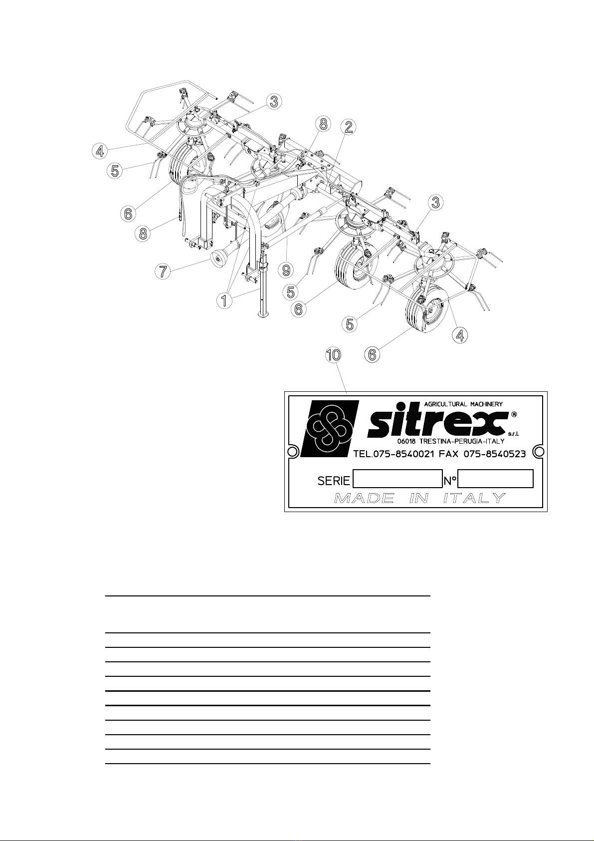
SUPPORTS AND WHEELS ASSEMBLY
1)
Mount the grease nipples 1 onto their seats on the hubs 2-3 (RH - LH).
2) Remove the spring pins 8 from the wheel supports 4-5 (RH-LH) and remove only
the upper shims 7.
3) Mount the wheel supports 4-5 (RH - LH) to their respective hubs 2-3 (RH - LH).
To do this, you must pull back lever “A” and then insert the upper pins of the wheel
supports 4-5 into the seats provided for them on the hubs 3-4. Then place the upper
shims 7 on the parts of wheel support pins 4-5 that protrudes from the seats of the
hubs 2-3 and secure the whole assembly in place with the spring pins 8. Position the
pins “A” on the central seats “B” provided for them on the hubs 2-3.
4) Attach the large hay guards 9 to the wheel supports 4-5, followed by the wheels
10, the small hay guards 11 and the washers 12 and fasten with the nuts 13.
In this steps, you will use:
Item 1: 4 grease nipple M6
Item 6: 4 shims ø30.5x39.8x0.5 (or 1) (ø1.2”x1.57”x0.02” (or 0.04”)
Item 7: 4 shims ø30.5x39.8x0.5 (or 1) (ø1.2”x1.57”x0.02” (or 0.04”)
Item 8: 4 spring pins ø6 x 45 (0.24” x 1.77”)
Item 12: 4 flat washers ø17 (0.67”)
Item 13: 4 nuts M16

11

12

13
STEP “A”
Attach the guard 1 to the central gear box
2 using the nuts 3.
In this step, you will use:
Item 3 : 2 nuts M8 (0.31“)
STEP “B”
NB. The plates “A” are assembled to the chassis of the machine by the
manufacturer. The assembly personnel may loosen screws “C” in order to make
it easier to assemble the frame 1. In this case, he must subsequently re-tighten
them correctly, otherwise the stability of the machine would be prejudiced.
Secure the frame 1 to the seats provided on the cross-member “B” and the plates “C”
using the screws 2, the spring washers 3, the nuts 4, the screws 5, the spring washers
6 and the nuts 4. Fit the grease nipple 7 to its seat on the frame 1.
In this step, you will use:
Item 2 : 4 screws M12x80 (0.47”x 3.15”)
Item 3 : 4 spring washers ø13 (ø0.51”)
Item 4 : 10 nuts M12 (0.47”)
Item 5 : 6 screws M12x35 (0.47”x 1.38”)
Item 6 : 12 washers ø13 (ø0.51”)
Item 7 : 1 grease nipple M6 (ø0.24”)

14
STEP “C”
Mount the pin 1 onto its seat on the frame 2. Fit the washer 3, the shim 4 and the bush
5 onto the pin and secure the whole assembly into place with the spring pin 6. Rise
the lever “A” so that the mobile plate “B” connected to it moves away from plate “C”
welded to the third point (3rd point hitch) 7. Assemble the 3rd point hitch 7 to the
frame 2, inserting items 1-3-4-5 and 6 into the seat in plate “C” and the bush of the
pin 1 between the lugs “D” of the 3rd point hitch 7. Then fasten in place with the pin
8 and the spring pins 9. Mount the pin 10 onto the lugs “D” of the 3rd point hitch 7
and fasten in place with the split pin 11.
In this step, you will use:
Item 3 : 1 shim ø30-50x5 (ø1.18”-2”x0.2”)
Item 4 : 1 shim ø40-50x20.5 (ø1.57”-2”x0.81”)
Item 5 : 1 bush ø48-40-30x44 (ø1.89”-1.57”-1.18”x1.73”)
Item 6 : 1 spring pin ø10x50 (ø0.39”x2”)
Item 8 : 1 pin ø25x113 (ø1”x4.45”)
Item 9 : 2 spring pins ø6x35 (ø0.24”x1.38”)
Item 11 : 1 split pin ø4 (ø0.16”)

15
STEP “D”
Return lever “A” to its original horizontal
position. Mount the supports 2-3 (RH-LH)
on their seats in the 3rd point hitch 1
using the pins 4 and the spring pins 5.
Mount the pins 6 onto their seats on the
supports 2-3 using the spring washers 7
and the nuts 8.
In this step, you will use:
Item 4 : 2 pins ø30x140 (ø1.18”x 5.51”)
Item 5 : 2 spring pins 8x50 (ø0.31”x2”)
Item 7 : 2 spring washers ø25 (ø1”)
Item 8 : 2 nuts M24 (0.94”)
STEP “E”-“F”
Fit the plug 1 onto the support leg 2.
Mount the support leg 2 onto the seat “A”
on the 3rd point hitch 3. Insert the spring
pin 4 into the seat provided in the leg 2.
Fasten the leg 2 to the 3rd point hitch
3 with the pin 5.
Mount the cardan shaft 6 onto the seat
provided on the 3rd point hitch 3 and fasten
it with the spring pin 7. Fit the fastener 8
onto the seat provided for it on the 3rd
point hitch 3 and fasten it with the screw 9,
the spring washer 10 and the nut 11.
In this step, you will use:
Item 4 : 1 spring pin 8x50 (ø0.31”x2”)
Item 5 : 1 pins 10x70 (ø0.39”x2.76”)
Item 7 : 1 spring pin ø3.5x18
(ø0.14”x0.71”)
Item 9 : 1 screw M4x16 (0.16”x0.63”)
Item 10 : 1 spring washer ø4.5 (ø0.18”)
Item 11 : 1 nut M4 (0.16”)

16
STEP “G”
Mount the shock absorbers 1 on the seats
provided for them on the 3rd point hitch 2
and the chassis of the machine 3 and
fasten them with the pins 4 and the spring
pins 5. Apply the eye bolts to the seats
provided on the chassis of the machine
and 6 and fasten them with the nuts 7.
In this step, you will use:
Item 4 : 4 pins 18x80 (ø0.71”x3.15”)
Item 5 : 4 spring pins ø6x35
(0.24”x1.38”)
Item 7 : 2 nuts M14 (0.55”)
STEP “H”
You will find the tine bars 1 (RH) and 2 (LH) in
four bundles (two RH and two LH) of six pieces
each. Tine bars 1 (RH) are attached to rotors 3-5.
Tine bars 2 (LH) are attached to rotors 4-6.
Continued on next page.

17
STEP “H”
(cont.d from previous page)
Attach the tine bars 1 (RH) and 2 (LH) to
their respective rotors 3-5 (RH) and 4-6
(LH) with screws 7, spring washers 8,
washers 8, screws 10 and nuts 11.
In this step, you will use:
Item 7 : 24 screws M12x30 (0.47”x1.18”)
Item 8 : 24 spring washers ø13 (ø0.51”)
Item 9 : 24 washers ø13 (ø0.51”)
Item 10 : 24 screws M12x35 (0.47”x1.38”)
Item 11 : 24 nuts M12
STEP “I”
Attach the lateral guard 1 (RH) and 2 (LH) to
the machine body using the screws 3-4 and
washers 5. Attach the grease nipples 6 in the
proper holes.
In this step, you will use:
Item 3 : 4 screws M12x25 (0.47”x1”)
Item 4 : 4 screws M12x20 (0.47”x0.79”)
Item 5 : 8 washers ø13 (ø0.51”)
Item 6 : 2 grease nipples M10
STEP “L”
Apply caps 4 to lateral guard 1-2 (RH-LH)
In this step, you will use:
Item 4 : 4 caps ø27 (ø1.06”)

18
STEP “M”
Attach the guards 3 (RH and LH side) and
plates 4-5 using washers 6 and screws 7.
Attach grease nipples 1-2 in the proper
holes (RH and LH side).
In this step, you will use:
Item 1 : 2 grease nipples M10
Item 2 : 4 grease nipples M6
Item 6 : 8 flat washers ø8.5 (ø0.33”)
Item 7 : 8 screws M8x16 (0.31”x0.63”)
ASSEMBLING STEPS FOR HYDRAULIC KIT

19
STEP “A”
Attach the cylinders 7-8 (RH-LH) using
pins 9 and spring pins 10.
In this step, you will use:
Item 9 : 2 pins ø20x70 (0.79”x2.76”)
Item 10 : 4 spring pins ø6x35 (0.24”x1.38”)
STEP “B”
Continue to secure cylinders 7-8 (RH-LH)
using pins 1 and spring pins 2.
In this step, you will use:
Item 1 : 2 pins ø20x95 (0.79”x3.74”)
Item 2 : 4 spring pins ø6x35 (0.24”x1.38”)
STEP “C-D”
Pass rope 6 trough loops 7 (RH and LH
side).
Pass hoses 2 and rope 6 trough loops 8 on
cylinder supports (RH and LH side).
Attach the eye hose 2 to hole 1 (RH and
LH side) using washers 3 and fitting 4.
Fasten rope 6 to lever 5. (RH and LH side)
In this step, you will use:
Item 2 : 2 hoses 1/4”x1040 (1/4”x41”)
Item 3 : 4 copper washers 3/8”
Item 4 : 2 fittings 3/8”

20
STEP “E”-“F”
Join hoses 2 to connector 1.
Attach nipple 3 to connector 1.
Attach hose 4 to nipple 3.
Secure hose 4 with collars 5 and
screws 6.
In this step, you will use:
Item 1 : 1 “T” connector 1/4”
Item 2 : 2 hoses (step C-D)
Item 3 : 1 nipple 1/4” - 3/8”
Item 4 : 1 hose 3/8”x2200 (3/8”x87”)
Item 5 : 4 hose collars ø18 (ø0.71”)
Item 6 : 4 screws M6x25 (0.24”x1”)
STEP “G”
Apply the support 1 to the 3
rd
point
hitch 2 by means of the washer 3 and
the screw 4.
In this step, you will use:
Item 3 : 1 washer ø11-30x2.5
(ø0.43-1.18”x0.1”)
Item 4 : 1 screw M10x25 (0.39”x1”)
Table of contents
Other sitrex Farm Equipment manuals

sitrex
sitrex BR 2030/6 User manual

sitrex
sitrex SM 3600 Quick setup guide

sitrex
sitrex QRX 12 Quick setup guide

sitrex
sitrex SB150 Quick setup guide

sitrex
sitrex MX 12 Quick setup guide

sitrex
sitrex MK14 MY15 User manual

sitrex
sitrex RP/4 Guide

sitrex
sitrex SR 420/11 H Guide

sitrex
sitrex RT/5200 Quick setup guide

sitrex
sitrex HM 360 Quick setup guide

sitrex
sitrex SR 320/8 H Guide

sitrex
sitrex TR/11 Quick setup guide

sitrex
sitrex GS 160 User guide

sitrex
sitrex MKE/18-20 User manual

sitrex
sitrex SR 320/8 User guide

sitrex
sitrex TR/6-S Quick setup guide

sitrex
sitrex SM/230 Assembly instructions

sitrex
sitrex BR 2030/6 User manual

sitrex
sitrex MX 8 Quick setup guide

sitrex
sitrex 250.799 User manual