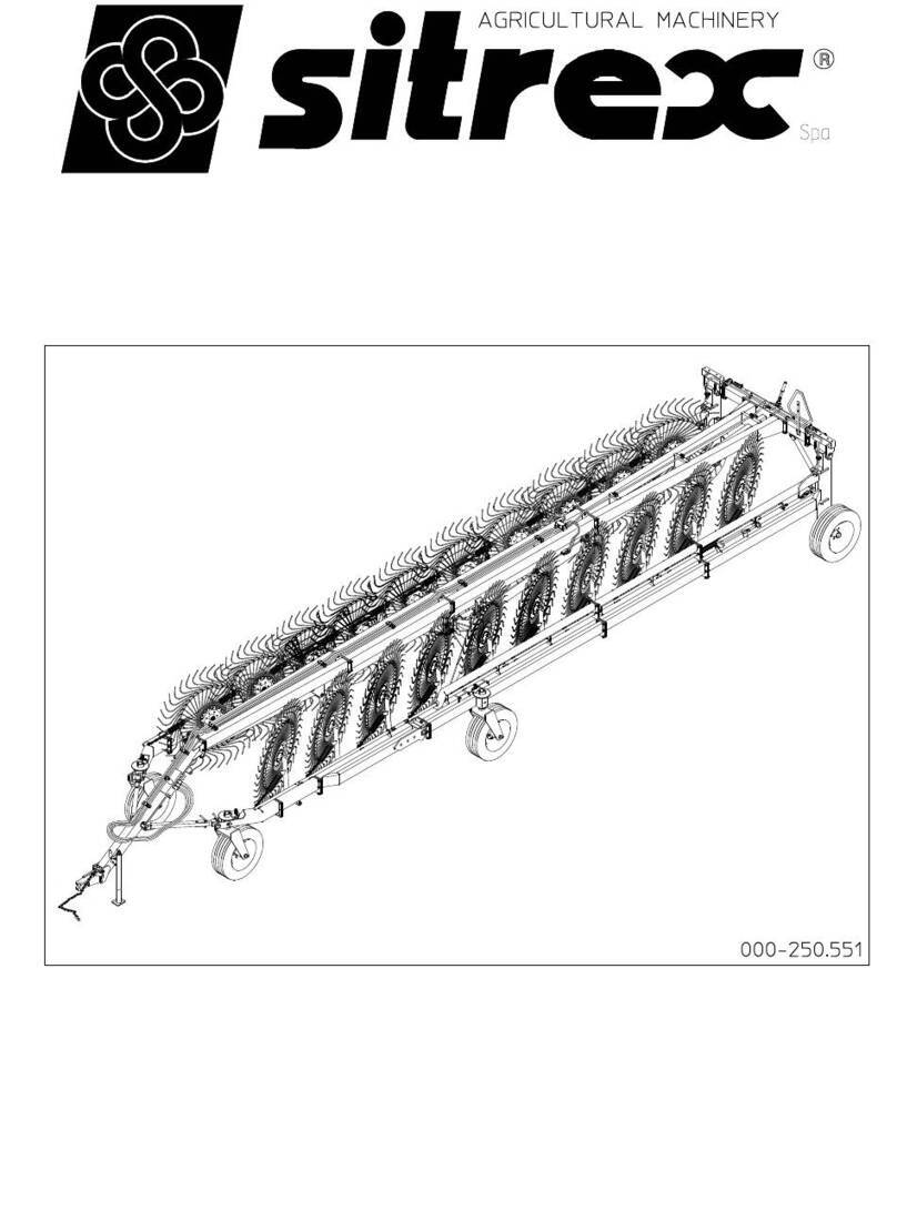
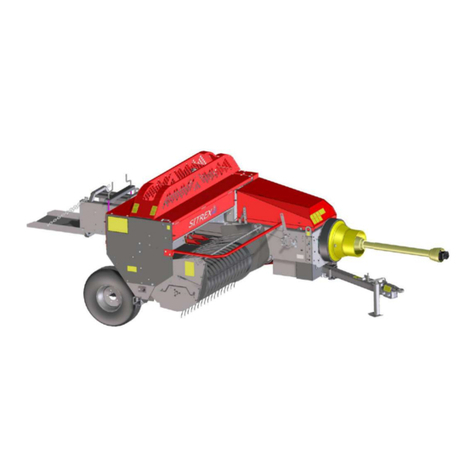
sitrex MX 12 Quick setup guide

ASSEMBLY, USE
AND MAINTENANCE
MX/12
0303


1
CONTENTS
CONTENTS ..................................................................................................................................1
1. Warrantee ..............................................................................................................................2
2. Technical characteristics ........................................................................................................3
3. General instructions for the operation and maintenance ........................................................4
4. Assembly instructions.............................................................................................................5
4.1 Warning signs .................................................................................................................5
4.2 Danger signs...................................................................................................................6
4.3 Technical notes...............................................................................................................6
5. Assembly steps ......................................................................................................................9
6. Connection to the tractor and transport ...........................................................................38
7. General instructions for field use......................................................................................41
8. General maintenance instructions ........................................................................................45
8.1 Repair work..................................................................................................................45
8.2 Laying up for extended periods .....................................................................................45
8.3 Maintenance direction ..................................................................................................46
9. Central wheels kit: instructions for installation ....................................................................47
10. Central wheels kit: adjustement for use ............................................................................52

WARRANTEE
2
1. Warrantee
On delivery, check that the meschine has not been damaged during transport and that all the
attachments are present. Claims must be made in writing to the agent within 8 days of receipt.
The manufacturer warrants new machinery at the time of delivery to the original purchaser to be
free from defects in material and workmanship if properly set up and operated in accordance with
this Operator's Manual.
The manufacturer undertakes to repair or replace free of charge any detective part which should
be returned by the purchaser (freight prepaid) and found to be detective by inspection authorized
by the manufacturer during the warranty period.
This warranty will be valid for 12 (twelve) months from the delivery of goods to the original
purchaser.
In case the customer is not in a position to return the defective part to the manufacturer, the
manufacturer cannot be held responsible for any cost due for repair or replacement of any part of
the machine, he will only supply the part(s) required for the repair and/or replacement.
The warranty is null and void when it is evident that the machine has been improperly used or
repaired or however repaired without authorization.
The manufacturer undertakes no responsability for any obligation or agreement reached by any
employers, agents or dealers, which are not in compliance with the above warranty. The
manufacturer cannot be held responsible for the consequent damages. This warranty substitutes
any other warranty, express or implied, and any other manufacturer's obligation.

TECHNICAL CHARACTERISTICS
3
2. Technical characteristics
Type of machine MX 12
Number of fingerwheels n° 12
Number of tines for wheels n° 40
Working width m(feet) 7.1 (23’ 3)
Operating speed km/h (Mph) 22.5 (14)
Minimum power required kW (HP) 22.4 (30)
Weight kg (Lbs) 1425 (3140)
Tyre size 205 - 65/15
Transport width m(feet) 2.5 (8’ 3”)

GENERAL INFORMATION
4
3. General instructions for the operation and maintenance
Before starting off for work, be sure that the machine is correctly assembled and in good
operating condition.
The front transport arms must always be attached during transport.
While the front transport arms are attached, do not operate for any reason whatsoever the
hydraulic cylinders for opening the machine or lifting the rake wheels.
When the machine is in movement, make sure that the brake on the front wheels does not block
wheel movement. The wheels must always pivot freely.
When in operation, do not turn around at full speed.
On particularly uneven ground, do not operate with the machine in the fully-opened position
(close machine at least 3’ compared to the fully-opened position). In addition, operate at a
reduced speed.
lf it is noticed that the machine is not operating properly (rake wheels putting too much pressure
on the ground, front wheels braked, etc.) the problem must be corrected immediately to avoid
causing damage to the machine.
If machine maintenance work, repairs or adjustments must be done in the field, they should be
done at a spot where the ground is firm and level. Turn off the tractor and apply the parking
brake. Use the proper tools and wear suitable protection (safety goggles, work gloves, etc.).
If any maintenance work, repairs or adjustments are done which require that some parts be
removed and/or that screws, nuts, pins, etc. be loosened or removed, always make sure that
everything is reassembled or retightened as it had been prior to making repairs or adjustments.
Follow the schedule provided for maintenance.
By following these suggestions it will be possible to keep the machine operating safely and
efficiently, to the benefit of the user.
IMPORTANT
DURING EXTENDED PERIODS OF INACTIVITY IT IS NECESSARY TO CLOSE COMPLETELY
THE CYLINDERS. THIS MUST BE DONE IN SUCH A WAY AS TO PROTECT THE RODS
FROM WEATHER EFFECTS.
THE RODS PARTS REMAINING OUTSIDE THE CYLINDER PIPE ( WHATEVER REASONS
MAY BE ) MUST BE CAREFULLY PROTECTED WITH A GREASE LAYER.
ASSEMBLY INSTRUCTIONS
5
4. Assembly instructions
Assembly must be done carefully and accurately, for the safety of the person(s) doing the
assembling and to ensure proper machine operation.
Assembly should be done on a flat, solid surface, using the proper tools and wearing suitable
clothing, making sure that all people not involved in the assembly be kept at a safe distance.
Assemblers must provide suitable lifting mechanisms and supports for stabilizing the partially
assembled units, so as to prevent them from falling and causing damage or injury. The steps for
assembly are illustrated in following. Depending on the experience of the assemblers and the
tools available, it is not necessary that the instructions be followed in the exact order given here,
but the safety precautions described above must always be followed carefully and scrupulously.
IMPORTANT
These signs and symbols give information to the operator on how to make the best use of the
machine so as to prolong life, avoid damage, optimise work and, above all, to avoid injury to the
operator and anyone within range of the machine.
4.1 Warning signs
A) Before beginning operations, read the
instruction manual carefully.
B) Before doing any maintenance or repair work,
stop the machine at a suitable spot. Turn off the
tractor motor, apply the brake, remove the key
from the ignition and consult this manual.

ASSEMBLY INSTRUCTIONS
6
C) This is a warning to use proper accident
protection when carrying out maintenance and
repairs
4.2 Danger signs
Indicates an impending dangerous situation which, if not
avoided, will cause death or severe personal injury.
Indicates a potentially dangerous situation which, if not
avoided, could cause death or severe personal injury,
including dangers which are present when protection is
removed.
indicates a potentially dangerous situation which, if not
avoided, can provoke less severe or minor injuries.
4.3 Technical notes
We will provide a few examples to make it easier to choose which of the various accessories to
use for each step of assembly. An approximate equivalent of the metric measurements is given
in inches.
DANGER
ATTENTION
CAUTION

ASSEMBLY INSTRUCTIONS
7
1) PINS AND SCREWS
Example: a pin with a 25 mm (1”) diameter and a screw
with an M 16 (5/8”) diameter, both 50 mm (2”) long, will
be listed as:
D25 x 50 (D 1” x 2”) and M 16 x 50 (D 5/8” x 2”).
2) SHIMS, SPACERS, BUSHINGS AND
WASHERS
Example: a shim, spacer, bushing or washer
with an inside diameter of 25 mm (1”), outside
diameter of 50 mm (2”) and thickness or length
of 13 mm (1/2”) will be listed as:
D25 - 50 x 13 (D 1” - 2” x 1/2”).
3) NUTS, GREASE NIPPLES
Example: a nut or grease nipple having a thread
of M 8 (5/6”) will be listed as:
M 8 (5/16”)

ASSEMBLY INSTRUCTIONS
8
4) PINS AND SPLIT PINS
Example: a pin or split pin having a
diameter of 8 mm (5/16”) and a length of
50 mm (2”) will be listed as:
D 8 x 50 (D 5/16” x 2”)
5) CLIPS
Example: a clip with a diameter of 3 mm
(1/8”) will be listed as:
D 3 mm (1/8”)
6) SPRINGS
Example: a spring with a wire diameter of 3
mm (1/8”), outside diameter of 25 mm (1”)
and length of 76 mm (3”) will be listed as:
D 3 - 50 x 76 (D 1/8”- 2” x 3”)

ASSEMBLY STEPS
9
5. Assembly steps
In the steps for assembly we will use the terms "RH part" and "LH part". The distinction is
conventionally made looking at the machine from the rear. For the purpose of simplification, we
will illustrate machine assembly for one side only; since the machine is symmetrical, each
operation must be done on both sides.
1. ATTENTION
Fit bushings 4 on proper seats of uprights 2 & 3. Attach the wheel supports 2 & 3 (LH - RH) to the
cross member assembly 1 using
pins 5, washers 6 & 7 and
screws 8. To identify parts 2 & 3
(LH - RH) see the next step.
NOTE: measurement labels
(see next figure) must be read
from the rear side of the
machine.
In this step, you will use:
Item 4:
4 - bushings D 50 - 60 x 50
(D 2" - 2" 3/8 x 2")
Item 5:
2 - pins D 50 x 190
(D 2" x 7" 1/2)
Item 6:
2 - washers D 23 - 75 x 12
(D 29/32"- 3" x 1/2)
Item 7:
2 - Grower washers
D23-35x4
(29/32" - 13/8" x 5/32")
Item 8:
2 - screws M 22 x 50
(7/8" x 2")
Item 9:
2 - grease nipples M 8
(5/16")
1

ASSEMBLY STEPS
10
2.
For correct assembly, the RH support 3 and the LH support 2 must lean in slightly towards the
center of the machine. After assembly, they must have the measurements given (minimum
width). At this point, before moving on to next step, keep in mind that the assembly is unstable
and therefore it is recommended that extreme caution be used.
NOTE: For the windrow width’s adjustment see page 43.
2

ASSEMBLY STEPS
11
3. ATTENTION
Attach plates 1 to cross member A. This is done in the following manner:
a) Insert screws 2 in the two upper holes of plates 1. Fasten screws 2 with nuts 3 without fully
tightening them, so that plates 1 are straddling cross member A.
b) Insert pin 7 in one of the joints of tie rod 9.
c) Insert pin 7, supporting tie rod 9, between plates 1.
d) Now insert screws 2 in the lower holes of plates 1. Fasten with nuts 3, without fully tightening.
e) At this point, insert the other joints of tie rod 9 between the welded plates E (LH support C and
RH support D) and fasten with the pins 8 and spring pin 4.
f) Check that the plates and tie rods are in the correct position, and then fasten pins 7 to plates 1
using washers 5 and screws 6.
g) Securely fasten plates 1 by fully tightening nuts 3. For this step you will use:
3

ASSEMBLY STEPS
12
In this step, you will use:
Item 2:
8 - screws M 16 x 165 (5/8" x 6" 1/2)
Item 3:
8 - nuts M 16 (5/8")
Item 4:
4 - spring pin D 5 x 36
(D 1" 13/64 x 1" 27/64 )
Item 5:
4 - washers D 12-36 x 2.5 (D 1/2" - 1" 27/64 x 3/32")
Item 6:
4 - screws M 12 x 20 (1" 5/32" x 13/16")
Item 7:
2 - pins D 22 x 120 (D 7/8" x 4" 23/32)
Item 8:
2 - pins D 22 x 108 (D 7/8" x 4" 1/4)
4. DANGER
Mount wheels 4 to hubs 1 (supports 2 & 3) using special nuts 5.
In this step, you will use:
Item 5:
10 - nuts M 16
(5/8"), fine pitch and spherical cap.
NOTE: the spherical side “A” of the
nut 5 must be always turned towars
the wheel rim flange.
4

ASSEMBLY STEPS
13
5. DANGER
Assembly 1 must be fully firmly stabilized. Wheels must be chocked with chocks 2 and a support
3must be placed under the cross member. The forks 4 of a forklift may also be used to support
the assembly.
5

ASSEMBLY STEPS
14
6. DANGER
Attach the rake wheel
sections 3 & 4 (LH - RH) to
supports 1 & 2 (LH - RH)
using pin 5, washer 6 and
screw 7. Attach grease nipple
8in the proper hole.
In this step, you will use:
Item 5:
2 - pins D 35 x 242
(D 1" 3/8" x 9" 1/2 )
Item 6:
2 - washers D 12-40 x 4
(D 1/12" - 1" 9/16 x 5/32" )
Item 7:
2 - screws M 12 x 20
(15/32" x 13/16" )
Item 8:
2 - grease nipples M 8
(5/16")
7. ATTENTION
Attach sections 3 & 4 (LH -RH) to the initial sections 1 & 2 (LH - RH) using screws 5 and nuts 6.
Fit in every wheels pipe bushings the grease nipple 7.
In this step, you will use:
Item 5:
8 - screws M 16 x 45
(5/8" x 1" 3/4)
Item 6:
8 - nuts M 16
(5/8")
Item 7:
12 - grease nipples M
6x45°
(1/4")
7
6

ASSEMBLY STEPS
15
8. ATTENTION
Attach end sections 3 & 4 (LH - RH) to sections 1 & 2 (LH - RH) using screws 5 and nuts 6. Insert
bushings 7 in the correct openings in
end sections 3 & 4 (LH - RH) and
fasten in place with spring pins 8.
In this step, you will use:
Item 5:
8 - screws M 16 x 45
(5/8" x 1" 3/4)
Item 6:
8 - nuts M 16
(5/8")
Item 8:
2 - spring pins D 8 x 70
(D 5/16" x 2" 3/4)
9.
When reaching this point, work with great caution, as the machine is not stable.
9
8

ASSEMBLY STEPS
16
10. CAUTION
Attach hub 1 to wheel 2 using screws 3 and nuts 4. Be sure to follow the indications in the
illustration during mounting.
In this step, you will use:
Item 3:
10 - screws M 16 x 1.5 x 40
(5/8" x 1" 19/32" fine pitch)
Item 4:
10 - nuts M 16 x 1.5
(5/8" fine pitch).
NOTE: the spherical side “A” off
the nut 7 must be always turned
towars the wheel rim flange.
11. CAUTION
Mount wheel-hub assembly 2 on bracket 1
using pin 3, spacers 4, washer 5 and nut
6.
in this step, you will use:
Item 3:
2 - pins D 30 x 270
(D 1" 13/16 x 10" 5/8)
Item 4:
4 - spacers D 30-38 x 30
(D 1" 3/16 - 1" 1/2" x 1" 3/16 )
Item 5:
2 - washers D 23-50 x 4
(D 7/8" - 2" x 5/32")
Item 6:
2 - nuts M 22 (7/8").
11
10

ASSEMBLY STEPS
17
12. ATTENTION
Insert bushings 5 in the holes in sections 1 & 2 (LH - RH) shown in the illustration. Place the
antifriction washer 4 on the pin of wheel
assembly 3, and insert the wheel assembly pin in
the correct holes in sections 1 & 2 (LH - RH) and
secure it with the flanged bushing 6 and the
spring pin 7. Attach grease nipples 8 to the
correct holes of sections 1 & 2 (LH - RH).
In this step, you will use:
Item 4:
2 - washers D 50-76 x 5
(D 2"-3" x 3/16")
Item 5:
4 - bushings D 50-60 x 50
(D 2"-2" 3/8 x 2")
Item 7:
2 - spring pins D 10 x 80
(D 13/32" x 3" 5/32)
Item 8:
2 - grease nipples M 8
(5/16")
12

ASSEMBLY STEPS
18
13. CAUTION
Place plate 2 with screw under flange 1 as shown in the illustration. Place upper plate 4 over
screw 3, followed by spring 5 and washer 6,
and tighten with nut 7.
NOTE: nut 7 should be tightened so as to
allow the bracket to pivot freely.
In this step, you will use:
Item 5:
2 - springs D 5-30 x 45
(D 13/64" - 1" 3/16" x 1" 25/32")
Item 6:
2 - washers D 12-36 x 2.5
(D 15/32" - 1" 27/64" x 3/32")
Item 7:
2 - nuts M 12
(15/32")
13
Table of contents
Other sitrex Farm Equipment manuals

sitrex
sitrex DM/6 Guide

sitrex
sitrex M 60 MINI/S User manual

sitrex
sitrex 250.799 User manual

sitrex
sitrex BR 2030/6 User manual

sitrex
sitrex MK14 MY15 User manual

sitrex
sitrex MKE/18-20 User manual

sitrex
sitrex SM/230 Assembly instructions

sitrex
sitrex BR 2030/6 User manual

sitrex
sitrex TR/11 Quick setup guide

sitrex
sitrex RT/5200 Quick setup guide

sitrex
sitrex SR 420/11 H Guide

sitrex
sitrex MX 8 Quick setup guide

sitrex
sitrex GS 160 User guide

sitrex
sitrex SR 320/8 User guide

sitrex
sitrex Action 120 User manual

sitrex
sitrex TR/6-S Quick setup guide

sitrex
sitrex SM 3600 Quick setup guide

sitrex
sitrex QRX 12 Quick setup guide

sitrex
sitrex RT/5800-H Quick setup guide

sitrex
sitrex HM 360 Quick setup guide