sitrex SR 320/8 H Guide

USE AND MAINTENANCE
SPARE PARTS LIST
SR 320/8 H
ROTARY RAKES
HYDRAULIC LIFT
Pull type
2011

2
Warranty
On delivery, check that the machine has not been damaged during transport
and that all the attachments are present. Claims must be made in writing to
the agent within 8 days of receipt.
The manufacturer warrants new machinery at the time of delivery to the
original purchaser to be free from defects in material and workmanship if
properly set up and operated in accordance with this Operator’s Manual.
The manufacturer undertakes to repair or replace free of charge any
defective part which should be returned by the purchaser (freight prepaid)
and found to be defective by inspection authorized by the manufacturer
during the warranty period.
This warranty will be valid for 12 (twelve) months from the delivery of goods
to the original purchaser .
In case the customer is not in a position to return the defective part to the
manufacturer , the manufacturer cannot be held responsible for any cost due
for repair or replacement of any part of the machine , he will only supply the
part(s) required for the repair and/or replacement.
The warranty is null and void when it is evident that the machine has been
improperly used or however repaired without authorization.
The manufacturer undertakes no responsibility for any obligation or
agreement reached by any employers, agents or dealers, which are not in
compliance whit the above warranty . The manufacturer cannot be held
responsible for the consequent damages. This warranty substitutes any other
warranty , express or implied , and any other manufacturer’s obligation.
CHAPTHER
1) GUIDE TO THE SIGNS
2) General summary of safety and accident-prevention instrutions
3) PRODUCT IDENTIFICATION
4) DELIVERY AND ASSEMBLY
5) ADJUSTMENT, PREPARATION AND USE INTRODUCTION
6) TRANSPORT BY ROAD
7) MAINTENANCE
8) SPARE PARTS LIST

3
GUIDE TO THE SIGNS AND SYMBOLS USED THIS MANUAL AND THEI
LOCATION ON THE MACHINE
IMPORTANT
These signs and symbols give information to the operator on how to make the best use of the machine so as
to prolong life, avoid damage, optimise work and, above all, to avoid injury to the operator and anyone within
range of the machine.
WARNING SIGNS
1) Before beginning operations, read the instruction manual carefully.
2) Before doing any maintenance or repair work, stop the machine at a
suitable spot. Turn off the tractor motor, apply the brake, remove the key
from the ignition and consult this manual.
3) This is a warning to use proper accident protection when carrying out
maintenance and repairs
DANGER SIGNS
4) Risk of possible ejection of blunt objects. Keep a safe distance
from the machine
5) Indicates that anyone coming within range of the moving tine arms
will be seriously injured.
Keep a safe distance from the machine.

4
6) Indicates that there is a risk of crushing your hands. Keep your
distance.
7) Indicates danger caused by accidental fall of suspended arms.
Keep safe distance.
8) Indicates that it is dangerous to touch the cardan (P.T.O.) shaft.
For all the other information regarding the cardan shaft, see the use
and maintenance booklet specifically for the cardan shaft which,
together with this manual, makes up the documentation on safety, use
and maintenance of the machine.
INDICATION SIGNS
9) Indicates a greasing point .
10) Shows the direction of rotation of the power takeoff and the
maximum number revolutions.
OIL LEVEL
11 Indicate a oil point.
MANUAL SIGNS.
Indicates an impending dangerous situation which, if not avoided, will
cause death or severe personal injury.
Indicates a potentially dangerous situation which, if not avoided, could
cause death or severe personal injury, including dangers which are
present when protection is removed.
indicates a potentially dangerous situation which, if not avoided, can
provoke less severe or minor injuries.
DANGER
ATTENTION
CAUTION

5
3) General Summary Of Safety And Accident-Prevention Instructions
Read all the directions carefully before using the machine. When in doubt, seek advice from the
manufacturers.
The manufacturing company declines all responsibility for non-compliance with the following safety and
accident-prevention instructions.
1- Pay attention to the danger signs and symbols in this manual and on the machine.
2- Do not touch moving parts.
3-All work on the machine (including adjustments) must always be carried out with the tractor immobilized
and the engine switched off.
4- On no account may persons or animals be carried on the machine.
5- Driving the tractor with the machine connected is absolutely forbidden to persons lacking suitable
experience, or who are in poor health, or who do not have a suitable driving license.
6- All accident-prevention measures recommended in this manual should be scrupulously observed.
7- Connecting the machine to the tractor creates a different weight distribution on the axles and so it is
essential to ensure that the tractor-machine combination is stable in all anticipated working conditions. It is
therefore necessary to have exact instructions from the tractor manufacturers. If such instructions are not
available, suitable tests should be conducted in safe conditions in order to assess stability.
8- Once the machine is connected, it can only be controlled through a cardan shaft complete with the
required overload protection and guard secured with the appropriate small chains. Be aware of the
rotational direction of the cardan shaft.
9- Before operating the tractor and machine, check that all transport and operational safety devices are
complete and working.
10- When driving on public roads, you should comply with the Highway Code regulations for the country
concerned.
11- Do not exceed the tractor axle maximum weight and the total mobile weight. Heed transport regulations.
12- Before starting work, familiarize yourself with the control devices and how they work.
13- Wear suitable clothes. Do not wear clothing which is loose or which could become entangled in rotating
or moving parts.
14- Connect the machine to a suitably powerful tractor by using an appropriate lifting unit and in accordance
with instructions.
15- Take maximum care when connecting and disconnecting the machine to and from the tractor.
16- The machine and any road transport attachments must bear the appropriate signs and symbols and
have suitable protection.
17- Never leave the driving seat when the tractor is running.
18- It is extremely important to appreciate that road holding, steering and braking may be significantly
affected with the machine attached.
19- When turning corners with the machine attached, be aware of the fact that the centrifugal force will alter
due to the change in the center of gravity.
20- Before engaging the power takeoff check the preset revolution speed. Do not change speed from 540
rpm to 1000 rpm.
21- Under no circumstances should anybody stand near the machine or any moving parts. It is the duty of
the operator to ensure that this requirement is respected.
22- Before leaving the tractor, lower the machine with the lifting unit, stop the engine, apply the parking brake
and remove the ignition key from the instrument panel.
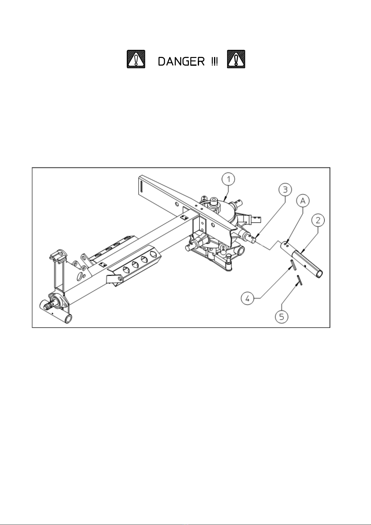
23- Under no circumstances should anybody go between the tractor and the machine (Fig. 1) when the
engine is running and the Cardan shaft is engaged, especially without first having applied the parking
brake and placed chocks against the wheels.

6
24- Before connecting or disconnecting the machine to or from the 3-point linkage, put the lifting unit lever
into the locked position.
25- The connection pins on the machine must match the connection sockets on the lifting unit.
26- During transport, secure the lateral lifting arms with the appropriate chains and tighteners.
27- When the machine is raised during road transport, put the tractor's hydraulic lifter lever into the locked
position.
28- Only use the Cardan shaft provided by the manufacturer and, in case of replacement, substitute it with
one having the same characteristics.
29- Regularly check all protection on the Cardan shaft. This should always be in excellent condition and
securely fixed.
30- It is important to ensure that the protection on the Cardan shaft is complete.
31- Connection and disconnection of the Cardan shaft must be carried out with the engine switched off.
32- Pay particular attention to the correct connection and safety of the Cardan shaft and the power takeoffs
on the machine and the tractor.
33- Prevent the cardan shaft protection from rotating using the chains supplied.
34- Before engaging the power takeoff, make sure that there are no people or animals in the vicinity and that
the selected engine speed corresponds to that permitted. Never go above the maximum permitted.
35- Do not engage the power takeoff when the engine is not running.
36- Always disengage the power takeoff when the Cardan shaft
is at too wide an angle (it should never be more than 35° see
fig) and when it is not in use.
37- Only clean and grease the Cardan shaft when the power
takeoff is disengaged, the engine is off, the parking brake is
applied and the ignition key is removed.
38- On disconnecting the Cardan shaft, replace the protective
hood on the power takeoff shaft.
39- Prolonged use of the machine can cause the drive boxes to
become hot. To avoid any risk of getting burnt, avoid touching
these areas both during use and some time afterwards.
40- Periodically check screws and nuts for tightness and grip.
Tighten if necessary.
41- When carrying out maintenance work or replacing the blades, raise the machine and rest on adequate
supports.
42- Use the quantities of grease and oil advised.
43- Spare parts must meet the requirements as defined by the manufacturer. Use only original spare parts.
44- Safety decals must always be clearly visible. They must be kept clean and replaced if they become too
illegible (they can be ordered from the agent if necessary).
45- The instruction booklet must be available for the lifetime of the machine.

7
PRODUCT IDENTIFICATION
MAIN PARTS
1) BRACKET
2) DRAWBAR
3) PARKING STAND
4) HYDRAULIC KIT
5) CRANK
6) RATCHET
7) FRAME
8) R.H. GUARD
9) TINE ARM
10) TINE
11) GEARBOX
12) AXLE
13) CYLINDER
14) TYRE ASSY
15) SWATHING DEFLECTOR
16) TELESCOPING TUBE
17) L.H. GUARD
RPM
TRACTOR
RPM
ROTORS
POWER
REQUIRED
WHEEL
TYPE
OPERATING
WIDTH
TRANSPORT
WIDTH
WEIGHT
MAX 540 75 HP 25 16X6.50 3,2Mt 1600 KG 466
KW 19 6PLY 126” 63” LBS 1030
IDENTIFICATION PLATE

8
LOCATION OF SIGNS AND SYMBOLS ON THE MACHINE
1) SEE DRAWING 1 P.4
2) SEE DRAWING 2 P.4
3) SEE DRAWING 3 P.4
4) SEE DRAWING 4 P.5
5) SEE DRAWING 5 P.5
6) SEE DRAWING 7 P.5
7) SEE DRAWING 10 P.6
8) SEE DRAWING 8 P.5
9) SEE DRAWING 9 P.6
11) SEE DRAWING 11 P.6
12) IDENTIFICATION PLATE

9
CHAPTER 4
DELIVERY AND ASSEMBLY
Checking the machine on delivery
All parts are carefully checked before dispacth or delivery.
On receiving the machine, ensure that it has not been damaged during
transport. If damage has occurred, contact the dealer concerned.
Details of packing are given below.
UNPACKING THE MACHINE
Lift the machine using a forklift truck, crane or other suitable equipment of sufficient
capacity after first checking the weight of the configurations in the table given below.
Check the stability and positioning of the load on the forklift truck forks or crane hook.
Keep the load as low as possible during movement for maximum stability and to ensure
that the operator has maximum visibility.
If a forklift truck is used, ensure that the forks are positioned as wide apart as possible.
WEIGT PACKING WEIGHT
KG 520 466
LBS 1150 1030
NOTE: 1) The packing consists mainly of wood which should be disposed of
according to the laws in force in the country where the machine is used.
The plastic film should also be disposed of according to the laws in
force in the country where the machine is used.
2) When storing, it is permissable to stack 2-3 crates on top of each othe.
Make sure that they are perfectly aligned certically.
3) In the event of further transport, ensure that the machine iwhen on the
transporting vehicle.

10
ASSEMBLY
Assembly is highly dangerous and must be carried out in strict accordance
with the following instructions. We recommend that assembly be performed
by qualified personnel. We also recommend that assembly be carried out in a
flat, open area with no people (particularly children) nearby who could be
severely injured if they were to touch or move any parts of the machine.
Assembly sequence:
Attach the arms (2) to the housing (1), placing them over the pins (3). Fasten
the arms by inserting spring pins (4) into holes (A), and then insert the inside
spring pins (5).
Attach the axle (2) to the housing (1). Insert pin (3) into hole and fasten with the spring pin.
Attach the cylinder (4) with the pin (5) and (6), fasten pin with the spring pin.

11
Attach the cylinder-adjustment assembly (2) to the drawbar (1), fastening
with the spring pin

12
Rest the main frame (2) on stands and then insert the wear bushings (5). Insert pin (3) into
hole (A) and fasten with the spring pin (42). Position the drawbar (1) so that pin (6) can be
inserted, and fasten pin (6) with the spring pin (7).
Mount wheels (10) on the axle pins, first placing the large guard (9) and then the small
guard (11), the washer (12) and tighten with the nut (13). Mount the parking stand (14) to
the mount on the drawbar (1), and fasten with pin (15) and clip (16). The machine can now
be placed on the ground.

13
Mount the grease nipple (1) on all bush.

14
HYDRAULIC SYSTEM ASSEMBLY
Assemble the oleo-dynamic system as shown. When using for the first time, make sure there are no oil
leaks. If there should be any, tighten the pipe fittings
Insert tube (16) to gearbox and attach the hose collar (17)-(19) to the lugs on axle. Mounting bush (15) to
tube.
Connect the fitting pipe (20) nipple (12) on cylinder.
Connect the fitting pipe (20) with fitting (18) on tube (6)
Connect the fitting (14) to tube (16), tube (16) its insert on the gearbox
Connect the rotating female ends of pipes (11) to fitting (14)
Attach the T connector (10) with lines (11) and (14), and fasten the lines into the working
position using the three line clamps (13) and (7), without pulling the lines tight; in the area
where the main frame is joined to the drawbar, the line must make an arch, so as to allow
movement between the two parts.
Check carefully to make sure that the opening of the tilt adjustment cylinder does not pull
on line (14). If it does, lengthen the loose section between the two line clamps (13) that
hold the lines in this area.
The short line (4) feeds the tilt adjustment cylinder and is attached by means of the nipple
and washer. Attach the tap (15) and quick-release coupling (16) to the end of line (14).
Check to make sure that all connections are correctly fastened.
Danger: the hydraulic cylinders are empty to start with, and the first time they are filled very dangerous
uncontrolled movements can take place. It is recommended that the cylinders be filled with oil before
connecting them to the machine, and the arms should be raised and lowered with the controls a few times in
order to eliminate air from the circuit. These operations must be done in complete safety conditions, with the
machine attached to the tractor and the operator sitting in the tractor driver’s seat working the hydraulic
controls, making sure that nothing and nobody is within the range of movement of the machine rake arms.

15
Mount the safety hook (2) by inserting it into hole (A), and then place the spring (4) and
washer (5) over the pin, fastening in place with pin (6). Insert safety pin (7) in hole (B).
Mount the right-hand protection frame 2-3 by inserting into the special hole (A) on
the drawbar and use screw 8 and pin 14 to fasten it.
Repeat the procedure on the left-hand protection of the machine.Assemble support 6
and 9 using screw 17. Use pin 11 to fasten the protection. Mount pin 20 and plate
nut 21.

16
Use screws (23) and (26) to mount group swathing deflector on plate carrier
extension (19). Insert extension on the protection

17
Attach the universal joint casing (2) using screws (3), nuts (4).

18
Before assembling the rake arms, raise the protection frames and use hook (23)
and plate (24) to hold them up. If the machine has to be set up for work, mount
detachable arms (44) on to the fixed arms (45) and fasten them with pin (43); the
two holes on the detachable arms are to adjust swath width. The maximum working
width is obtained by assembling the arm on the innermost hole. If the machine has
to be prepared for transport or for storage, mount the detachable arms in position
(R) in holes (A) on the frame.

19
CHAPTER 5
ADJUSTMENT, PREPARATION AND USE
INTRODUCTION
Connection to the tractor is higly dangerous. Take great care and carry out the entire
operation in strict compliance with the following instruction.
Nobody should go near the area between the tractor and the machine.
Check that all warning and danger signs are in place and legible.
Check that the tractor is in good running order. Check the engine oil, gerbox oil, brake
fluid and cooling water levels as well as the tyre pressures.
Refer to the tractor operator’s manual.
CONNECTION TO THE TRACTOR
Connect the machine to the tractor, hitching it to the drawbar bar at point (1). If the
two-point crosspiece is used, lock the equalizers (10) using the optional screws (8)
and nuts (9). Attention: do not use screws (8) if the machine is hitched to the
drawbar. After the machine is hitched, loosen the parking stand (2) and remove pin
(3), then rotate the stand upward towards the back of the machine and insert pin (3) to
hold it in the resting position.
Once this procedure is completed, insert the quick-release coupling (4) into the tractor
socket and open the tap (the lever must be parallel with the line, as shown in the
illustration). At this point, work carefully with the hydraulic distributor to make sure that
the frame is completely lowered, then adjust the height of the tines above the ground.
To change the distance between the tines and the ground, turn screws (6). By rotating
the crank (7), the tilt of the machine relative to the ground is adjusted.

20
CONNECTING THE CARDAN SHAFT
More detailed information may be found in the cardan shaft manual which, together with this manual, is an
essential part of the accident-prevention documentation.
It is your responsibility to read and comply with this documentation. If information given in this manual should
conflict with that given in the cardan shaft manual, you should follow the instructions given by the cardan
shaft manufacturer.
Fit the cardan shaft and check that the shaft is connected correctly both at the tractor end and at the machine
end. For more details, see the descriptions on the following pages.
If a safety system is provided, this should be fitted to the machine end, not to the tractor end.
During both transport and use, avoid conditions where the cardan transmission shaft is extended to the
maximum. In all working conditions, the telescopic tubes must overlap by at least 1/3 of their length ).
Conversely, when the cardan shaft is contracted to the maximum, there should still be a gap of approximately
50 mm (2") .
Take particular care when connecting the two cardan shaft end forks and make sure that they are fully
secured. This is achieved by inserting the safety pins and bolts (1) in the special slots (2) on the power
takeoff shafts on both the tractor and machine ends.
Aloose shaft could come apart and cause considerable mechanical damage and serious injury to persons.
Table of contents
Other sitrex Farm Equipment manuals

sitrex
sitrex TR/6-S Quick setup guide

sitrex
sitrex SR 320/8 User guide

sitrex
sitrex MK14 MY15 User manual

sitrex
sitrex BR 2030/6 User manual

sitrex
sitrex RT/5800-H Quick setup guide

sitrex
sitrex MKE/14-16 User manual

sitrex
sitrex DM/6 Guide

sitrex
sitrex SR 420/11 H Guide

sitrex
sitrex QRX 12 Quick setup guide

sitrex
sitrex MX 8 Quick setup guide

sitrex
sitrex MKE/18-20 User manual

sitrex
sitrex TR/11 Quick setup guide

sitrex
sitrex DM/4 Guide

sitrex
sitrex SM 3600 Quick setup guide

sitrex
sitrex GS 160 User guide

sitrex
sitrex 250.799 User manual

sitrex
sitrex RT/5200 Quick setup guide

sitrex
sitrex M 60 MINI/S User manual

sitrex
sitrex HM 360 Quick setup guide

sitrex
sitrex Action 120 User manual