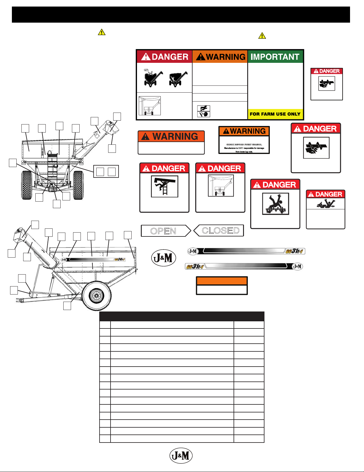
J&M GC31t-1 User manual

J&M Manufacturing Co, Inc
284 Railroad Street - P.O. Box 547 | Fort Recovery, OH 45846 | Ph: (419) 375-2376 | Fax: (419) 375-2708
www.jm-inc.com
Rev. 11.24.2020
GRAIN CART
OPERATOR’S MANUAL
MODEL GC31t-1
Manual

2
Stance
Right
OAS (Opposite Auger Side)
Left
AS (Auger Side)
Front
Rear

3
Table of Contents
4....................................................................................To the Dealer
5.............................................................................General Information
6...................................................................................Specications
7............................................................................... Bolt Torque Chart
8-9 ....................................................................... Safety Rules and Decals
10 ..............................................................Initial Operation and Maintenance
11-12 ......................................................................Operating Instructions
12 ............................................................ Loading & Unloading the Grain Cart
12 .......................................................................... Routine Maintenance
13 ...................................................................Lubrication Service Schedule
14 ...............................................................................Troubleshooting
15 ....................................Removing Dirt from the Restrictors on the Hydraulic Cylinder
15 .......................................................................Adjusting the Slip Clutch
15 ..................................................................Adjusting the Lower Flighting
16 ......................................................................Adjusting Upper Flighting
16 ............................................................................Storage Preparation
16 ........................................................................Removing From Storage
Repair Parts & Diagrams
17 ....................................................................................Wheel Rims
17 ...........................................................................................Tires
18 ....................................................................... Hub & Spindle Assembly
19 ...........................................................Power Take O (PTO) Shaft Assembly
20 .............................................................................Driveline Assembly
20 ...........................................................................130 Degree Gearbox
21 ................................................... Main Frame & Under-Carriage Axle Assembly
22 ................................................................................Hitch Assembly
22 ........................................................................Lower Level Tank Panels
23 ..........................................................................Mid-Level Tank Panels
23 ..................................................................................Rail Assembly
24 ................................................................Lower and Mid Level Track Parts
25 ........................................................Upper Level Tank Panels and Sideboards
26 ............................................................................ Interior Tank Braces
27 ..................................................................Lower Auger & Tube Assembly
28 .........................................................................Upper Auger Assembly
29 ......................................Sliding Upper Auger, Tube, & Flow Control Spout Assembly
30-31 .............................Hydraulic Hoses, Cylinders & Fittings For Standard Upper Auger
32-33 .....................Hydraulic Hoses, Cylinders & Fittings For Hydraulic Sliding Upper Auger
34-35 .....................................................Auto-Gate Shut-O Hydraulic Schematic
36 .................................................................. Auto-Gate Shut-O Assembly
37 ...........................................................Auto-Gate Shut-O Wiring Schematic
38 ..............................................................................Lights and Wiring
39 ........................................................................... 5 Point Scale System
40 ............................................................................Inspection Windows
40 ..................................................................................Miscellaneous
41 ..........................................................................Door Wheel Assembly
42-43 ..........................................................................Roll Tarp Assembly
44 ........................................................................Spring Return Assembly

4
To The Dealer
Read manual instructions and safety rules. Make sure all items on the Dealer’s Pre-Delivery and Delivery Check Lists in the
Operator’s Manual are completed before releasing equipment to the owner.
The dealer must complete the Warranty Registration found on the Dealer Portal website located at dealer.jm-inc.com. and return
it to J. & M. Mfg. Co., Inc. at the address indicated on the form. Warranty claims will be denied if the Warranty Registration has not
been submitted.
EXPRESS WARRANTY:
J. & M. Mfg. Co. Inc. warrants against defects in construction or materials for a period of ONE year. We reserve the right to inspect
and decide whether material or construction was faulty or whether abuse or accident voids our guarantee.
Warranty service must be performed by a dealer or service center authorized by J. & M. Mfg. Co., Inc. to sell and/or service the type
of product involved, which will use only new or remanufactured parts or components furnished by J. & M. Mfg. Co., Inc. Warranty
service will be performed without charge to the purchaser for parts or labor based on the Warranty Labor Times schedule. Under
no circumstance will allowable labor times extend beyond the maximum hours indicated in the Warranty Labor Times schedule for
each warranty procedure. The purchaser will be responsible, however, for any service call and/or transportation of the product to
and from the dealer or service center’s place of business, for any premium charged for overtime labor requested by the purchaser,
and for any service and/or maintenance not directly related to any defect covered under the warranty. Costs associated with
equipment rental, product down time, or product disposal are not warrantable and will not be accepted under any circumstance.
Each warranty term begins on the date of product delivery to the purchaser. Under no circumstance will warranty be approved
unless (i) the product warranty registration card has been properly completed and submitted to the equipment manufacturer,
and (ii) a warranty authorization number has been issued by the equipment manufacturer. This Warranty is eective only if the
warranty registration card is returned within 30 days of purchase.
This warranty does not cover a component which fails, malfunctions or is damaged as a result of (i) improper modication or
repair, (ii) accident, abuse or improper use, (iii) improper or insucient maintenance, or (iv) normal wear or tear. This warranty
does not cover products that are previously owned and extends soley to the original purchaser of the product. Should the original
purchaser sell or otherwise transfer this product to a third party, this implied, with respect to tires or other parts or accessories not
manufactured by J. & M. Mfg. Co., Inc. Warranties for these items, if any, are provided separately by their respective manufacturers.
THIS WARRANTY IS EXPRESSLY IN LIEU OF ALL OTHER WARRANTIES OR CONDITIONS, EXPRESS, IMPLIED OR STATUTORY,
INCLUDING ANY IMPLIED WARRANTY OF MERCHANTABILITY OR FITNESS FOR PARTICULAR PURPOSE.
In no event shall J. & M. Mfg. Co., Inc. be liable for special, direct, incidental or consequential damages of any kind. The exclusive
remedy under this Warranty shall be repair or replacement of the defective component at J. & M. Mfg. Co., Inc’s. option. This is the
entire agreement between J. & M. Mfg. Co., Inc. and the Owner about warranty and no J. & M. Mfg. Co., Inc. employee or dealer is
authorized to make any additional warranty on behalf of J. & M. Mfg. Co., Inc.
The manufacturer reserves the right to make product design and material changes at any time without notice. They shall not
incur any obligation or liability to incorporate such changes and improvements in products previously sold to any customer,
nor shall they be obligated or liable for the replacement of previously sold products with products or parts incorporating such
changes.
SERVICE:
The equipment you have purchased has been carefully manufactured to provide dependable and satisfactory use. Like all
mechanical products, it will require cleaning and maintenance. Lubricate the unit as specied. Observe all safety information in
this manual and safety signs on the equipment.
For service, your authorized J. & M. dealer has trained mechanics, genuine J. & M. service parts, and the necessary tools and
equipment to handle all your needs.
Use only genuine J. & M. service parts. Substitute parts may void warranty and may not meet standards required for safety and
satisfactory operation. Record the model number and serial number of your equipment in the spaces provided:
Model No: GC31t-1 Grain Cart Serial No: ________________________ Date of Purchase:_______________
Purchased From: ________________________________________________________________________________
Provide this information to your dealer to obtain correct repair parts.

5
General Information
TO THE OWNER:
The purpose of this manual is to assist you in operating and maintaining your grain cart in a safe manner. Read it carefully. It
furnishes information and instructions that will help you achieve years of dependable performance and help maintain safe
operating conditions. If this machine is used by an employee or is loaned or rented, make certain that the operator(s), prior to
operating:
1. Is instructed in safe and proper use.
2. Reviews and understands the manual(s) pertaining to this machine.
Throughout this manual, the term IMPORTANT is used to indicate that failure to observe can cause damage to equipment. The
terms CAUTION, WARNING and DANGER are used in conjunction with the Safety-Alert Symbol (a triangle with an exclamation
mark) to indicate the degree of hazard for items of personal safety. When you see this symbol, carefully read the message that
follows and be alert to the possibility of personal injury or death.
This Safety-Alert symbol indicates a hazard and means ATTENTION!
BECOME ALERT! YOUR SAFETY IS INVOLVED!
Indicates an imminently hazardous situation that, if not avoided, will
result in death or serious injury.
Indicates a potentially hazardous situation that, if not avoided, will
result in death or serious injury, and includes hazards that are exposed
when guards are removed.
Indicates a potentially hazardous situation that, if not avoided, may
result in minor or moderate injury.
Indicates that failure to observe can cause damage to equipment.
Indicates helpful information.
DANGER
WARNING
CAUTION
IMPORTANT
NOTE

6
Specications
Note: Specications are subject to change without notice or obligation.
* Bushel capacities measured with #2 corn at 15% moisture, 56 lb. (25,4 kg)
test weight.
** Time varies with rpm and moisture contet
JG
K
M
L
D
C
F
BE
H
A
SPECIFICATIONS
Capacity
Auger, One Vertical
Unload Rate
Unload Time
Wheels
Tires
Hubs
Spindle Size
PTO
Tongue Weight
Empty
Loaded
Total Weight (approx.)
23,8 Tons (30,8 m3)
45,7 cm diameter
11,3 tons (14,3 m3) per minute
2,1 minutes
27x32 or 30x32
30.5x32 or 900/60R32 (176LI)
10 Bolt
11,4 cm diameter
1000 rpm
575 kg
1700 kg
4900 kg
31,3 Tons (40,5 m3)
45,7 cm diameter
11,3 tons (14,3 m3) per minute
2,8 minutes
30x32 or 44x32
900/60R32 (185LI) or 76x50.00
10 Bolt
15,2 cm diameter
1000 rpm
1300 kg
1900 kg
6525 kg
GC24t-1 GC31t-1
DIMENSIONS
Specications are subject to change without notice or obligation.
® Registered Trademark of J. & M. Mfg., Co., Inc.
A
B
C
D
E
F
G
H
J
K
L
M
48,2 cm
446 cm
193 cm (standard)
221 cm (with HS-18)
235 cm (with HS-18XL)
487,7 cm
670 cm
379 cm (standard)
412 cm (with HS-18)
429 cm (with HS-18XL)
221 cm (standard)
259 cm (with HS-18)
276 cm (with HS-18XL)
350,5 cm
358,1 cm
337 cm
304,8 cm
381 cm
45,7 cm
574 cm
237 cm (standard)
275 cm (with HS-18)
294 cm (with HS-18XL)
670,6 cm
901,7 cm
410 cm (standard)
442 cm (with HS-18)
455 cm (with HS-18XL)
181 cm (standard)
212 cm (with HS-18)
225 cm (with HS-18XL)
370,8 cm
358,1 cm
353,1 cm
289 cm to 304 cm
380 cm to 431 cm
GC24t-1 GC31t-1

7
Bolt Torque Chart
Always tighten hardware to these values unless a dierent torque or tightening procedure is listed for specic application.
Fasteners must always be replaced with the same grade as specied in the manual parts list.
Always use the proper tool for tightening hardware: SAE for SAE hardware and Metric for Metric hardware.
Make sure fastener threads are clean and you start thread engagement properly.
All torque values are given to specications used on hardware dened by SAE J1701 & J1701M (JUL 96)
TIGHTENING WHEEL NUTS
Standard 3/4”wheel studs and nuts should be tightened to torque 500 Ft.-Lbs and standard 22mm studs should be tightened
to torque 700 Ft.-Lbs. During initial operation of the grain cart and then checked for proper torque after every 10 hours of use.
Failure to do so may damage wheel nut seats. Once seats are damaged, it will become impossible to keep nuts tight.
A
A
SAE SERIES
TORQUE
CHART
METRIC SERIES
TORQUE
CHART
10.9
8.8
Diameter
(Inches)
AWrench
Size
1/4
5/16
3/8
7/16
1/2
9/16
5/8
3/4
7/8
1
7/16”
1/2”
9/16”
5/8”
3/4”
13/16”
15/16”
1-1/8”
1-5/16”
1-1/2”
6
12
23
36
55
78
110
192
306
467
8
17
31
48
75
106
149
261
416
634
10
19
35
55
85
121
170
297
474
722
13
26
47
75
115
164
230
403
642
979
14
27
49
78
120
171
240
420
669
1020
18
37
67
106
163
232
325
569
907
1383
MARKING ON HEAD
SAE 2 SAE 5 SAE 8
LBS.-FT. LBS.-FT. LBS.-FT.N-m N-m N-m
Diameter
&
(Millimeters)
Thread Pitch
6 x 1.0
8 x 1.25
10 x 1.5
12.1.75
14 x 2.0
16 x 2.0
18 x 2.5
20 x 2.5
22 x 2.5
24 x 3.0
30 x 3.0
10 mm
13 mm
16 mm
18 mm
21 mm
24 mm
27 mm
30 mm
34 mm
36 mm
46 mm
8
20
39
68
109
169
234
330
451
571
1175
6
15
29
50
80
125
172
244
332
421
867
11
27
54
94
151
234
323
457
623
790
1626
8
20
40
70
111
173
239
337
460
583
1199
8
21
41
75
118
181
263
367
495
623
1258
6
16
30
55
87
133
194
270
365
459
928
11
29
57
103
163
250
363
507
684
861
1740
8
22
42
76
120
184
268
374
505
635
1283
6 x 1.0
8 x 1.0
10 x 1.25
12.1.25
14 x 1.5
16 x 1.5
18 x 1.5
20 x 1.5
22 x 1.5
24 x 2.0
30 x 2.0
Metric 10.9Metric 8.8Metric 8.8 Metric 10.9
MARKING ON THREADMARKING ON THREAD
COARSE THREAD FINE THREAD
Wrench
Size
Diameter
&
(Millimeters)
Thread Pitch
Metric Bolt Head
Identication
SAE Bolt Head
Identication
Metric
Grade 8.8
Metric
Grade 10.9
SAE Grade 2
(No Dashes)
SAE Grade 5
3 Radial Dashes
SAE Grade 8
6 Radial Dashes

8
Safety Rules
ATTENTION! BECOME ALERT! YOUR SAFETY IS INVOLVED!
Safety is a primary concern in the design and manufacture of our products. Unfortunately, our eorts to provide safe equipment
can be erased by an operator’s single careless act. In addition, hazard control and accident prevention are dependent upon the
awareness, concern, judgment, and proper training of personnel involved in the operation, transport, maintenance and storage of
equipment.
Make certain that the operator(s), prior to operating is instructed in safe and proper use and reviews and understands the manual(s)
pertaining to this machine. Also make certain that the operator(s) reviews and understands the operator’s manual of the tractor
prior to hooking up or operating the grain cart.
Read this manual before you operate this machine. If you do not understand any part of this manual, or need more information,
contact the manufacturer or your authorized dealer.
SAFETY
Understand that your safety and the safety of other persons is measured by how you service and operate this machine. Know the
positions and functions of all controls before you try to operate them. Make sure to check all controls in a safe area before starting
your work.
The safety information given in this manual does not replace safety codes, federal, state or local laws. Make certain your machine
has the proper equipment as designated by local laws and regulations.
A frequent cause of personal injury or death is from persons falling o equipment and being run over. Do not permit persons to
ride on this machine.
Travel speeds should be such that complete control and machine stability is maintained at all times. Where possible, avoid operating
near ditches, embankments and holes. Reduce speed when turning, crossing slopes and rough, slick or muddy surfaces.
Collision of high speed road trac and slow moving machines can cause personal injury or death. On roads, use asher lights
according to local laws. Keep slow-moving-vehicle emblem visible. Pull over to let faster trac pass.
Hydraulic oil leaking under pressure can penetrate skin and cause infection or other injury. To prevent personal injury,
• Relieve all pressure, before disconnecting uid lines,
• Before applying pressure, make sure all connections are tight and components are in good condition,
• Never use your hand to check for suspected leaks under pressure. Use a piece of cardboard or wood for this purpose.
• If injured by leaking uid, see your doctor immediately.
When transporting the grain cart, always keep the auger in the stow position.
Use care when moving of operating the grain cart near electric lines as serious injury or death can result from contact.
Never adjust, service, clean, or lubricate the grain cart until all power is shut o. Keep all safety shields in place. Keep hands, feet,
hair and clothing away from moving parts while the grain cart is in operation.
The service ladder is for service work only. If you must climb into the grain tank, be certain that all power is shut o and then use
extreme caution when climbing into the grain cart.
Make sure that everyone is clear of equipment before applying power or moving the machine.
Make sure that the grain cart is fastened securely to the tractor by using a high strength hitch pin, clip and safety chains. Make sure
that the grain cart hitch properly matches the hitch type of the tractor. Use a single prong (spade) grain cart hitch with a double
prong (clevis) tractor hitch. Use a double prong (clevis) grain cart hitch with a single prong (spade) tractor hitch.
Before lling the grain cart, make certain that no one is inside the grain tank. Never allow children or anyone in, near, or on the
grain cart during transport or during loading and unloading of grain. Be aware that moving grain is dangerous and can cause
entrapment, resulting in severe injury or death by suocation.
Never operate the auger system with anyone inside the grain tank. Hands, feet, hair and clothing can t through the openings in
and around the grate. Contact with the auger can cause severe injury or death. Make certain that all power is shut o before service
work is performed.
Before unhooking the grain cart from the tractor, be sure the jack stand is properly mounted and in place and the wheels are
properly blocked to prevent the cart from moving.

9
Safety Decals
ATTENTION! BECOME ALERT! YOUR SAFETY IS INVOLVED!
Replace Immediately If Damaged or Missing
IMPORTANT: Install new safety signs if the
old signs are destroyed, lost, painted over
or cannot be read. When parts are replaced
that have safety signs, make sure you install
a new sign with each new part. New signs
are available from the manufacturer or your
authorized dealer.
1
2
34
5
10 11
6 7
8 9
DO NOT ENTER GRAIN TANK WHEN
AUGER IS RUNNING.
1
9 3
77
5
2
916
9
9
12
13
12 & 13
14
15
16
SERIOUS INJURY OR DEATH CAN RESULT
FROM CONTACT WITH ELECTRIC LINES.
USE CARE WHEN MOVING OR OPERATING
THIS MACHINE NEAR ELECTRIC LINES
TO AVOID CONTACT.
KEEP HANDS, FEET, HAIR AND
CLOTHING AWAY FROM MOVING PARTS
ROTATING DRIVELINE
CONTACT CAN CAUSE DEATH.
KEEP AWAY!
• Keep all guards in place when operating.
• Do NOT stand on steps or climb ladder until
all power is shut off.
• Keep hands, feet, hair and clothing away
from moving parts.
10
6
4
11
7
5
16
9
12
15
14
13
Do not inflate tires more than 6 PSI over the recommended
pressure printed on the side of the tire.
CHECK TIRE INFLATION
OPERATING INSTRUCTIONS
Do not operate or service machine until you
read and understand operator’s manual.
Dealer or manufacturer is not responsible for damaged caused by
loose wheel nuts.
CHECK ALL WHEEL NUTS
To prevent serious injury or death:
• R elieve pressure on system before
r epairing, adjusting or disconnecting.
• W ear proper hand and eye protection
w hen searching for leaks.
• K eep all components in good repair.
HIGH-PRESSURE FLUID HAZARD
Do not adjust, service, clear, or lubricate the machine until all
power is shut off.
Keep all safety shields in place.
Keep people and objects clear of equipment before applying
power or moving machine.
Before highway travel, secure a slow-moving vehicle emblem to
the rear of the machine in accordance to the state and local
laws.
Make sure all flashers and turn/brake lights are working properly
BEFORE incidental highway travel.
•
•
•
•
•
•
FLOWING GRAIN TRAPS AND SUFFOCATES VICTIM IN SECONDS!
With the gate indicator in the closed position, fill the box with
grain.
With the PTO disengaged, fold discharge auger to upright
position.
After auger is in the upright position, start the PTO at a SLOW
RATE OF SPEED until the pin on the upper auger engages the
drive dog on the bottom auger(failure to follow this procedure
may cause extensive damage to both the drive dog and the pin).
Increase PTO speed to 1000 RPM and open inner gate until the
pointer is in the halfway position. When grain begins flowing
from the discharge auger, open gate to the full position.
Once the grain has ceased to flow, return the gate to the closed
position (for complete clean-out, gradually close gate, allowing
the opening to be reduced). Disengage the PTO and allow its
rotation to come to a complete stop. Auger is now ready to be
returned to the lowered position.
•
•
•
•
SERIOUS INJURY OR
DEATH CAN RESULT WITH
ELECTRIC LINES.
USE CARE WHEN MOVING
OR OPERATING MACHINE
NEAR ELECTRIC LINES TO
AVOID CONTACT.
NEVER PLAY IN OR
ON GRAIN CART YOU CAN DIE IN
SECONDS IN
FLOWING GRAIN!
JM0037665
KEEP HANDS AND CLOTHING
AWAY FROM MOVING PARTS.
JM0076817
CHECK WHEEL LUGS
CHECK BEFORE EVERY SEASON.
Manufacturer is NOT responsible for damage
from loose lug nuts.
JM0025435
CHECK PTO OVERLAP
CHECK MANUAL FOR PTO LENGTH.
INCORRECT PTO OVERLAP MAY CAUSE
EXTENSIVE DAMAGETO DRIVE SYSTEM.
Description Part No.
1 Danger_Warning_Important JM0037665
2 Danger, Keep Hands and Clothing Away Decal (Small) JM0076817
3 Warning, Keep Hands Away Decal JM0018039
4 Warning, Keep Lug Nuts Tightened Decal 1-5/8”x 4” JM0010150
5 Danger, Keep Hands and Clothing Away Decal JM0018035
6 Danger, Keep O Ladder Decal JM0018034
7 Danger, Electric Lines Decal JM0015099
8 Danger, Do Not Enter Grain Tank Decal JM0018033
9 Danger, Rotating Driveline Decal JM0018036
10 Open Decal JM0025433
11 Closed Decal JM0025434
12 J&M Oval Decal (Large) 9-1/2” x 15” JM0015151
13 J&M Oval Decal (Medium) 5-1/2”x8-1/2” JM0010179
14 GC31t-1 OAS Stripe Complete JM0046656
15 GC31t-1 AS Stripe Complete JM0046655
16 Check PTO Overlap Decal JM0025435

10
Initial Operation & Maintenance
WARNING
BE CERTAIN THAT ALL POWER IS SHUT OFF BEFORE SERVICING THE GRAIN CART.
Before the grain cart is put into service:
Have the safety instructions been read and clearly understood by the operator(s) of this machine?
Has the gearbox been properly lled with EP-80-90 gearbox lubricant?
Have all nuts, bolts, bearings and braces been properly fastened?
Has the PTO been checked for proper overlap?
IMPORTANT: Has the slip clutch on the PTO been serviced? If the slip clutch is left unchecked, damages to the power-take-o
and drive shaft may result. Before using the grain cart, loosen the bolts around the slip clutch. Make sure the friction plates turn
free of each other and are not corroded together. Re-tighten the tension bolts. Run the auger system EMPTY and check for proper
engagement of the slip clutch.
CHECK PTO OVERLAP LENGTH. Overlap length may vary depending on the tractor model and hitch setting. Try to obtain the
greatest possible overlap without bottoming out in the extreme operating conditions. Too much overlap may cause the PTO to
bottom out and damage the driveline. Not enough overlap may cause the PTO front and back halves to separate. From the fully
compressed (shortest) length the PTO should be telescoped (extended) between 10” and 22”. Dierent PTO lengths may need
to be purchased to accommodate your terrain. A 4” shorter or a 10” longer PTO can be ordered through your dealer from J&M
Manufacturing.
GREASE BEARINGS: Are all bearings on the drive line properly greased? Are all set screws in the bearings and U-joints tight? Has
the power-take-o shaft been properly greased at all points including the cross bearings? Has the universal joint at the gearbox
been greased? Have all grease points at the auger hinge area, including the hanger bushing assembly been greased?
TIRE PRESSURE: Are the tires properly inated? The following is to be used as a general guide for tire ination for cyclic use.
Figures can vary depending on specic brand of tire used. It is important that tires are inspected before and after the unit is
loaded. The tire should stand up with no side wall buckling or distress as the tire rolls. Do Not Exceed The Tire Pressure
Indicated Below:
Tire Size psi
900/60R32 Lug Tires, 193 Load Index Rating (Alliance) 67
1050/50R32 Lug Tires (185LI) (Alliance) 63
1250/50R32 Lug Tires (188B LI) (Firestone) 23

11
Operating Instructions
VERY IMPORTANT: Under no circumstance is it recommended to tow a loaded grain cart in excess of 8 mph.
WHEEL NUTS: Are the wheel nuts properly fastened? Torque to 700 Lbs.-Ft. for standard 22mm wheel studs and nuts. Torque
to 500 Lbs.-Ft. for 3/4” wheel studs and nuts. Torque to 350 Lbs.-Ft. for 5/8” wheel studs and nuts. Wheel studs and nuts
should be checked after each load during initial operation of the cart and then after every 10 hours of use. Failure to do so
may damage wheel studs and nuts. Once the seats are damaged, it will become impossible to keep the lug nuts tight.
The drawing shows the proper way to mount the wheels using Budd-type nuts. The wheels supplied with
your grain cart have straight holes and the Budd nuts will be mounted according to Figure 1. Wheels that
are improperly installed on the grain cart, resulting in product failure, will nullify warranty and shift the
burden of liability to the owner/operator. We recommend you inspect your wheel nuts to make sure they
are properly installed. Also, check the wheel nuts on a regular basis to ensure they are tight.
LIGHTING AND SAFETY DECALS: Are the rear, amber extremity lights properly positioned? Extend the lights within 16” (40,6cm)
of the left and right extremities of the grain cart. Is an SMV Emblem attached to the rear of the grain cart?
Are the lights working properly? Are all lights and reective decals clean, visible and properly placed?
BE CERTAIN THAT ALL POWER IS SHUT OFF WHEN HOOKING UP TO TRACTOR OR CONNECTING HYDRAULIC LINES TO
TRACTOR.
Preparing the Grain Cart for Use: Model 812 and 24t-1 requires a 150+ HP tractor. Models 1012, 1112, 1122 and 31t-1 requires a 225+
HP tractor. Models 1222, and 1312 requires a 250+ HP tractor. Models 1412 and 1522 require a 300+ HP tractor.
IMPORTANT: Do NOT pull a loaded grain cart on highway. For incidental highway travel, observe the section below.
Tow Loads Safely
Stopping distance increases with speed and weight of towed loads, and on slopes. Towed loads with or without brakes that are too
heavy for the tractor or are towed too fast can cause loss of control. Consider the total weight of the equipment and its load.
Observe these recommended maximum road speeds, or local speed limits which may be lower.
Road Travel (grain cart empty): Do not travel more than 32 km/hr (20 mph) and do not tow loads more than 1.5 times the
pulling unit’s weight.
Ensure the load does not exceed the recommended weight ratio. Use additional caution when towing loads under adverse surface
conditions, when turning, and on inclines.
WARNING: For greater stability on uneven or steep terrain, position non-scale wheel spindles at the furthest out setting.
IMPORTANT:
1) Connect grain cart hitch to tractor drawbar using a good quality hitch pin. Attach the safety chain to the tractor and through one
chain loop provided on either side of the grain cart frame as shown. Make sure the grain cart hitch properly matches the hitch of
the tractor. Use a single prong (spade) grain cart hitch with a tractor double prong (clevis) hitch. Use a double prong (clevis) grain
cart hitch with a single prong (spade) tractor hitch.
Safety Chain User Instruction
a) Secure the safety chain by looping it around the each side of the grain cart as shown and
connecting to the towing machine’s attaching bar.
b) Do Not allow any more slack than necessary for articulation.
c) Do Not use any intermediate support as the attaching point.
d) Store the safety chain by securing it around the main axle A-frame of the grain cart.
e) Replace the safety chain if one or more links or end ttings are broken, stretched or otherwise
damaged or deformed.
2) Attach the power-take-o shaft to the tractor. The PTO must have at least 10”of engagement. Check tractor drawbar for clearance
and length and adjust if necessary. Make sure the PTO does not bottom out when making sharp turns as it may bend the drive
shaft.
3) Make sure the jack stand is removed from the lower support position before the cart is moved. Never use the jack to support
a loaded grain cart.
4) Be sure that no debris or foreign objects are in the grain cart.
Figure 1
Continues on next page.

12
Operating Instructions (Continued)
5) Attach the hydraulic lines to the tractor. Two hydraulic lines (green band) operate the inside gate mechanism. Connect these
lines to one service outlet on the tractor. Two hydraulic lines (yellow band) operate the folding mechanism of the auger. Connect
these lines to a second service outlet on the tractor. The remaining two hydraulic lines (red band) operate the hydraulic ow control
spout located at the end of the upper auger. Connect these lines to a third service outlet on the tractor. Make sure the air is bled
from the hydraulic cylinders and hoses.
6) Run the auger system EMPTY before loading grain into the tank for actual use. Make certain that the slip clutch is operating and
that the upper and lower augers are properly engaged.
7) Connect the lighting 7-prong connector end on the main wiring harness to the tractor electrical outlet. Make sure that all asher
and turn indicator lights are working properly before incidental highway travel.
CAUTION
• Do NOT operate the grain cart before reading and understanding the Operator’s Manual and ALL danger, warning and
caution signs.
• Be sure that a Slow-Moving-Vehicle emblem is attached to the rear of the grain cart.
• Never exceed 1,000 rpm on the PTO and driveline system.
• Never fold or extend the auger until the PTO has come to a complete stop.
• Never ll the grain cart unless the gate indicator is in the closed position.
• Never allow foreign object (shovels, etc.) to be placed inside the grain cart.
• Never engage the lugs and drive dogs on the augers when the system is moving at a high rate of speed.
• Never perform maintenance work or service the grain cart with the tractor running.
1) With the gate indicator in the closed position, ll the tank with grain.
2) With the PTO disengaged, fold the discharge auger to the upright position.
3) IMPORTANT: After the upper auger is in the upright position, be sure to start the PTO at a SLOW RATE OF SPEED until the lugs
on the upper auger engage the drive dog on the bottom auger. Failure to follow this procedure may cause extensive damage to
both the drive dog and the drive line.
4) Increase the PTO speed and slowly open the inside tank gate until the gate indicator rod located above the upper auger is
halfway between the Open and Closed position. When grain begins owing from the discharge auger, continue to open the gate
to obtain the desired unload rate.
5) To stop unloading grain, return the inside tank gate to the closed position and allow the material inside the auger to unload.
For complete cleanout, gradually close the inside tank gate. Once the grain has ceased to ow, disengage the PTO and allow
its rotation to come to a complete stop. The upper auger is now ready to be returned to the stow position. IMPORTANT: Do Not
Pull the grain cart through the eld with the unloading auger in the upright position. Failure to return the auger to the lowered
stow position may damage the hinge and greatly reduce the life of the auger system.
WARNING
BE CERTAIN ALL POWER IS SHUT OFF WHEN SERVICING THE GRAIN CART
• Repack the wheel bearings at least once a year. Use Bearing Gard MK1 or equivalent lubricant. Also check the seal for wear
and replace if necessary.
• Check the grain cart periodically for cracks in welds and for other structural damage. Have cracked welds xed immediately.
Failure to do so could result in extensive damage to the grain cart and greatly reduce the life of the cart.
• Lubricate the slides on the clean-out door.
• Check all hydraulic hoses for wear and replace as necessary.
• Make sure all tires are properly inated. See INITIAL OPERATION AND MAINTENANCE in the Owner’s Manual for
recommended instructions for tire pressure. It is important that tires are inspected before and after unit loaded.
• Check PTO for wear of plates in the slip clutch. Replace if needed.
• Make sure that all guards and shields are in place before operating the grain cart.
Loading and Unloading the Grain Cart
Routine Maintenance

13
Lubrication Service Schedule
IMPORTANT: Your grain cart has grease ttings at all critical points. These should be serviced before the grain cart is put into
operation.
WARNING: BE CERTAIN THAT ALL POWER IS SHUT OFF BEFORE SERVICING THE GRAIN CART
GEARBOX: Gearbox lubricant has been added to the gearbox
during nal assembly. Recheck the lubricant level before initial
operation of the grain cart, then periodically according to use. An
inspection plug is located in the center of the top of the gearbox
mount plate. To check the uid level, remove the vented inspection
plug and drain plug at the bottom of the gearbox. Drain the
lubricant. Return the drain plug and rell the gearbox with 24
ounces (0,71 liters) of gearbox lubricant. The gearbox is properly
lled when half full of lubricant. DO NOT OVERFILL. Use EP 80-90
gearbox lubricant or equivalent.
SPRING LOADED UPPER AUGER BEARING: Service the
grease tting on the upper auger bearing (located at the top
end of the upper auger assembly) after every 8 hours of use.
Lubricate the springs and retaining bolts on the bearing before
prolonged storage of the grain cart.
AUGER FOLDING MECHANISM: One grease tting is located on
the pivot pin of the folding auger. This tting should be serviced
after every 8 hours of use. Service the grease tting on the hanger
bushing assembly (top end of the lower auger assembly) after every
8 hours of use or as needed.
PTO & DRIVELINE: The grease ttings on the
PTO should be serviced after every 8 hours of use.
Service the grease ttings on each of the drive
bearings and also the universal joint after every 8
hours of use.
HITCH: There is a grease tting located on the
pivot shaft of the swivel hitch for grain carts
equipped without an electronic weigh system
(scales).

14
Troubleshooting
WARNING
MAKE SURE THAT ALL POWER IS SHUT OFF BEFORE SERVICING THE GRAIN CART. MAINTENANCE AND REPAIR SERVICE WORK TO BE
PERFORMED BY QUALIFIED SERVICEMEN ONLY.
Trouble... Possible Cause... Possible Remedy...
Auger will not return to down position or
move from stow position.
Dirt In Restrictor (see pg. 15)
Faulty Check Valve
Upper ighting and lower ighting are
locked together (see pg. 15)
Remove restrictor ttings from outside
hydraulic cylinder and clean out dirt
Replace Check Valve
Bearing on top of upper auger ighting
need adjusting. When the auger is in the
engaged position, there must be 1/8”
(0,32cm) gap between bottom of top
bearing and top of upper tube housing
(SEE ADJUSTING THE UPPER AUGER
FLIGHTING)
Hanger Bushing Assembly at the top of
the lower auger ighting is hot
Top of the hanger bushing assembly is
rubbing against the drive dog
Loosen the two bolts and re-adjust the
position of the hanger bushing assembly.
Re-tighten bolts.
Remove the lower ighting assembly and
place a shim between the spline coupler
and the gearbox.
Excessive Vibration Auger ighting or shaft is bent
Drive shaft is bent
Straighten or replace auger ighting
Replace or straighten drive shaft
Grain ow stoppage Bolt sheared in drive dog
Folding auger before complete stop
Replace bolt in drive dog. Engage upper
and lower ighting at a slow rate of
speed. (Drive dogs and lugs are being
engaged too fast.)
Upper and lower ightings are
disengaging before auger comes to
a complete stop. Replace bolt in the
drive dog. Never engage or disengage
the upper and lower ightings until the
augers come to a complete stop.
Auger tube is breaking away from the
grain cart at the hinge area or the ram in
the hydraulic folding cylinder is bent
Upper auger is extended in the upright
position while traveling in the eld
Repair or place folding cylinder if
necessary. Remember to lower auger to
the eld position after unloading.
Slip Clutch is not working properly. Pressure plates (linings) corroded
together
Loosen the bolts around the slip clutch
on the PTO, run PTO, allow clutch to slip
and retighten to proper tension
Slip clutch not working properly
PTO key sheared
Inspect slip clutch linings and replace if
worn.
Replace key and tighten set screw.

15
Removing Dirt from the Restrictors on the Hydraulic Cylinder
After the rst hour of operation, the slip-disc clutch on the PTO should be checked for overheating. After the rst hour, the slip-
disc clutch should be checked weekly or anytime there is excessive slippage of the friction discs. The slip-disc clutch should be
checked for moisture, which could cause corrosion on the drive plates. If the grain cart has been idle for an extended period of
time, or in wet weather, check to make sure that the friction lining plates are not rusted or corroded together. The friction lining
plates are 1/8”(0,32cm) thick new. They should be replaced after 1/32”(0,08cm) of wear to ensure proper operation.
IMPORTANT: If the machine has never been used or has not been operated for one (1) season, the following is recommended.
When the grain cart has been idle for an extended period of time, it is important to check the slip-disc clutch to make sure that it
will slip when an obstacle or load heavier than the torque setting is encountered. Use the following procedure to make certain
that the slip-clutch will slip and give the overload protection required.
1. Loosen the nut on the springs until the springs can rotate, yet remain secure on the bolts.
2. Place a mark on the outer plate of the slip-disc clutch.
3. Securely attach the PTO and the grain cart to the tractor and start the tractor.
4. Engage the PTO for several seconds then quickly disengage it.
5. Turn the tractor o.
6. The friction lining plates should have been broken loose or“slipped”. Check the marks placed on the outer plates of the slip-
disc clutch. If the marks are aligned, the friction plates are not working properly.
7. Adjust the nuts on the springs to set the spring compression height to 1.27 inches (3,23cm).
WARNING
MAKE SURE THAT ALL POWER IS SHUT OFF BEFORE ADJUSTING THE FLIGHTING ASSEMBLY.
If the drive-dog and hanger assembly are becoming excessively hot during unloading, the lower ighting and/or hanger may need
adjusting. The hanger bushing assembly has elongated holes where it attaches to the outer tube assembly. Loosen the two 3/8”
bolts on the hanger bushing assembly. Adjust the hanger either up or down and vertically center it between the ighting and drive
dog. Re-tighten the bolts. Make certain that the ighting center and drive-dogs do not rub the hanger bushing assembly, causing
them to become hot.
If the hanger can no longer be adjusted by moving it up or down on the elongated holes, both the hanger bushing assembly and
the lower ighting will have to be removed. After removing them from the tube assembly, place a shim [between 1/8” (0,32cm) to
3/16” (0,48cm) thick] where the gearbox and the spline coupler (welded to the lower ighting). Replace the lower ighting and
reattach the hanger to the tube assembly. Readjust the hanger assembly. NOTE: The bottom of the lower ighting is not attached
to the gearbox with any bolts or set screws but may be‘frozen’fast. Be careful when removing the lower ighting from the gearbox.
For easier removal of the lower ighting, keep the gearbox at the bottom intact, remove the 2 3/8” bolts from the hanger bushing
assembly and pull the lower ighting o of the gearbox.
After adjusting the lower ighting, move the upper auger to the unload position and check the upper ighting for readjustment.
WARNING
MAKE SURE THAT ALL POWER IS SHUT OFF AND THE UPPER AUGER TUBE IS IN THE DOWN POSITION BEFORE
REMOVING THE RESTRICTORS
Remove restrictors from the 90 degree street elbow on the hydraulic cylinder. Remove dirt from the tting to allow hydraulic
oil to ow through the restrictor. Reattach the restrictor to the street elbow. Use teon sealant tape or equivalent on the
threads of the restrictor before re-attaching.
If the restrictor continues to plug with dirt, replace the restrictor or lter the hydraulic oil in your system.
Adjusting the Slip Clutch
Adjusting the Lower Flighting

16
Adjusting the Upper Flighting
WARNING
MAKE SURE ALL POWER IS SHUT OFF BEFORE ADJUSTING THE FLIGHTING ASSEMBLY
If the upper and lower augers to do not properly separate during the unfolding sequence, the upper ighting may need adjusting.
Before making adjustment to the upper ighting, check to see if the lugs and drive dogs on the auger assemblies are locking
together. If they are not locked together, check to see if dirt is in the restrictor or if a faulty check valve on the hydraulic cylinder
used to raise and lower the upper auger assembly may be causing the problem. If dirt is in the restrictor, see “Removing Dirt From
Restrictors On Hydraulic Cylinders” below.
Fold the upper tube assembly into the upright position. Position the upper ighting in the engaged position with the lower ighting.
Locate the four-hole ange bearing on the top of the upper auger tube housing. With the upper ighting in the engaged position,
check the spacing between the upper bearing and the upper tube housing. There must be an 1/8” (0,32cm) space between the
base of the four-hole ange bearing and the upper tube housing. If there is NOT a space between the bearing and the upper tube
housing, or if there is more than 1/8” (0,32cm) space, the upper ighting will need to be adjusted. To adjust the upper ighting,
loosen the 1 1/4” hex nuts both above and below the four-hole ange bearing. Move the 1 1/4” hex nuts up or down the threaded
shaft on the top of the auger ighting shaft until the bearing moves to approximately 1/8” (0,32cm) above the base of the upper
tube housing. When the four-hole ange bearing is properly located, tighten both 1 1/4” hex nuts together to secure the bearing
position.
If the upper and lower ighting still does not separate properly during the folding sequence, a small bevel may need to be removed
from the inside of the lugs where they engage the drive dogs on the auger assemblies. Grind approximately 1/8”(0,32cm) from the
corner of the lugs where they touch against the drive dogs.
IMPORTANT: When the grain cart is not going to be used for a period of time, store the cart in a dry, protected place. Leaving
your grain cart outside, open to the weather will shorten it’s life.
Follow the procedure below when your grain cart is placed in storage for periods up to six months.
1. Cover electronic monitor (if equipped) with plastic before washing the grain cart. Wash or clean and completely lubricate
the grain cart. See the lubrication service section in this manual.
2. Remove all grain from inside the grain tank, auger tube assemblies, and at the clean-out door.
3. Check the gearbox oil and replace with new EP 80-90 gearbox lubricant or equivalent if necessary.
4. Touch up areas where paint may have worn away. Use a good quality primer paint, especially before re-applying graphite
paint to the interior slopes of the grain tank.
5. Retract all hydraulic cylinders to prevent the piston rods from rusting.
6. If the grain cart is equipped with an electronic weigh system, fully charge the battery to prevent freezing. Disconnect the
negative (-) ground cable at the battery to prevent possible discharge.
7. Clean the tires before storage. Inate the tires at regular intervals.
8. Open the clean-out door at the base of the grain tank.
9. Loosen the Slip Clutch Tension Bolts.
1. Check the gearbox to make sure it has the appropriate amount of oil.
2. If equipped with an electronic scale system, check the battery and make sure that it is fully charged. Reconnect the negative
(-) cable.
3. Inate the tires to the correct operating pressure.
4. Close the clean out door at the base of the grain tank.
5. Make sure all safety shields are in the proper position.
6. Tighten the Slip Clutch Bolts on the PTO until the spring length is 1.27 inches (3,23cm).
Storage Preparation
Removing from Storage

17
Repair Parts & Diagrams
When performing maintenance work, wear sturdy, rough-soled work shoes and protective equipment for eyes, hair, hands,
hearing and head. Follow the Operator’s Manual instructions to ensure safe and proper maintenance and repair.
Your local, authorized dealer can supply genuine replacement parts. Substitute parts may not meet original equipment
specications and may be dangerous.
WARNING
MAKE SURE ALL POWER IS SHUT OFF BEFORE PERFORMING ANY MAINTENANCE OR REPAIR WORK.
Tires for Grain Carts
Wheel Rims for Grain Carts
Description Part No.
Wheel Rim, 10 hole, 32”x 30” (30x32-10) JM0020005
32x36-10 Hole Wheels JM0020052
40x32-10 Hole Wheels JM0020056
Description Part No.
900/60R32 Lug Tires (192D LI) (Alliance) JM0047182
1050/50R32 Lug Tires (185LI) (Alliance) JM0045024
1250/50R32 Lug Tires (188B LI) (Firestone) JM0032060

18
Hub & Spindle Assembly
Description Part No.
1 G250-10 Hub, Spindle, and Bearings Assembly with 22mm Studs, Races and Nuts (HSA-1075-22) JM0019927
2 1”-8 Gr5 Z Centerlock Hex Nut JM0002149
3 1”-8 x 8” Gr5 Z Hex Bolt JM0001487
4 Spindle, 6”x 29-3/4” (628) JM0019102
5 Seal 55179 (Type C) for G250-10,G300-10B, Spring-assisted (CR55179) JM0019179
6 Large Bearing (71455) JM0019112
7 Large Race (25,000#) (71750) JM0019198
8 Hub with races, 22mm studs & nuts (13.19 bolt circle) (11.13 pilot) (H25000) JM0019300
9 Wheel Stud (22mm x 90mm) (22-MMS) JM0019178
10 Wheel Nut 22mm with Washer (22-MMNW) JM0019192
11 Small Race (25,000#) (653) JM0019195
12 Small Bearing (663) JM0019177
13 3/16” Spindle Washer (2.5”ID, 4.5” OD) (H25000) (EM-25M) JM0019106
14 2-7/16”-12 Gr5 Z Slotted Spindle Nut (SF-2512) JM0019108
15 3/8” x 3-1/2” Z Roll Pin (3754) JM0020001
16 Dust Cap with Gasket (Bolt-on) 7-3/4” OD (D-25000) JM0019109
17 1/4”-20 x 1” Gr5 Z Hex Bolt JM0002095

19
Power Take O (PTO) Shaft Assembly
Description Part No.
1 Complete Collar Yoke C15 (Comer) 1 3/4”-20 (28428) JM0025180
1 Complete Collar Yoke C15 (Comer) 1-3/8” (28426) JM0025181
2 Cross Journal Set (Comer PTO)(18130) JM0025144
3 Outer Yoke (Comer PTO)(18133) JM0025145
4 Roll Pin for Outer Tube (Comer PTO)(00243) JM0025146
5 Bushing with Grease Nipple (Comer PTO)(18210) JM0025147
6 Complete Outer Tube (Comer PTO)(30710) JM0025148
7 Inner Tube (Comer PTO)(90010) JM0025149
8 Roll Pin for Inner Tube (Comer PTO)(00271) JM0025150
9 Inner Yoke (Comer PTO)(18134) JM0025151
10 Complete Disc Clutch (Comer PTO)(84033) JM0025152
11 Retain Collar for Outer Tube (Comer PTO)(19121) JM0025153
12 Retain Collar for Inner Tube (Comer PTO)(19122) JM0025154
13 Complete Guard (Comer PTO)(27820) JM0025155
14 Outer Circlip (Comer PTO)(00452) JM0025156
15 Sliding Sleeve Collar (Comer PTO)(16490) JM0025157
16 Spring for Spring Lock Yoke (Comer PTO)(15107) JM0025158
17 Fixed Sleeve (Comer PTO)(16489) JM0025159
18 Ball 5/8” (Comer PTO)(00085) JM0025160
19 Yoke C15 (Comer PTO)(18428) JM0025161
20 Spring (Comer PTO) (Compression for Slip Clutch) 7/8”x 1-1/2”(14022) JM0025162
21 Flanged Yoke (Comer PTO)(18016) JM0025163
22 Bushing (Comer PTO)(1909) JM0025164
23 Lining Ring (Comer PTO) 3-1/2” ID x 6” OD(19018) JM0025165
24 Metric Bolt (12 mm x 1-1/4 mm x 65 mm) & Lock Nut(00502) JM0025166
25 Clutch Support F40 (Comer PTO)(18453) JM0025167
26 Inner Plate (Comer PTO)(19014) JM0025168
27 Intermediate Plate (Comer PTO)(19115) JM0025169
28 Pressure Plate (Comer PTO) (19116) JM0025170
29 Metric Bolt (10 x 1.5 x 100) & Nut (Comer PTO) (00548) JM0025171
30 Female Tube & Yoke (Comer PTO) (80039) JM0025172
31 Male Tube & Yoke with Roll Pin (Comer PTO) (80529) JM0025173
32 Half Female Guarding (Comer PTO) (67820) JM0025174
33 Half Male Guarding (Comer PTO) (37820) JM0025175
34 Front Half PTO, 1-3/4”(Comer) (21110) JM0025176
34 Front Half PTO, 1-3/8”(Comer) (21110-138) JM0025177
35 Back Half PTO, 1-3/4”(Comer) Including Clutch (36510) JM0025178
36 Complete 1-3/4”PTO (Comer) (103600) JM0020024
36 Complete 1-3/8”PTO (Comer) (103555) JM0020021
37 Tee Key for Plastic Retain Collar (PTK-2) JM0025179

20
Driveline Assembly
Description Part No.
1 Casting, Upper Half for Superior Gearbox (18-20”) (A0150) JM0025088
2 Casting, Lower Half for Superior Gearbox (18-20”) (A0149) JM0025089
3 1-3/4” Input Shaft for Superior Gearbox (18-20”) (A0142) JM0025090
4 1-3/4” Output Shaft for Superior Gearbox (18-20”) (A0143) JM0025091
5 18 Tooth Gear for Superior Gearbox (18-20”) (H61S18) JM0025092
6 29 Tooth Gear for Superior Gearbox (18-20”) (H61S29) JM0025093
7 Shim, Arbor for Superior Gearbox (18-20”) (H00101-01) JM0025094
8 Bearing Cup for Superior Gearbox (14-20”) (414276) JM0025077
9 Bearing Cone for Superior Gearbox (14-20”) (514137) JM0025078
10 Bearing Cup for Superior Gearbox (18-20”) (413620) JM0025095
11 Bearing Cone for Superior Gearbox (18-20”) (413687) JM0025096
12 Seal for Superior Gearbox (18-20”) (617285) JM0025097
13 End Cap for Superior Gearbox (14-20”) (400301) JM0025076
14 2-1/4” Bolt for Superior Gearbox (438225) JM0025085
15 Solid Plug for Superior Gearbox (14-20”) (400300) JM0025080
16 Bushing (1/2” x 1/4” reducer) for Superior Gearbox (4003VB) JM0025073
17 Vented Plug for Superior Gearbox (2003PR) JM0025081
18 Plain Plug for Superior Gearbox (200300) JM0025075
19 130 Degree Gearbox Complete (Superior) (18-20”) (H130-9) JM0017840
Description Part No.
1 Drive Shaft Guard (74-1/2”) JM0012517
2 Mid-Drive Shaft Guard (54-3/4”) (31T) JM0028415
3 Rear Drive Shaft Guard (53-1/8”) (31T) JM0028426
4 U-Joint, 44R (252288) JM0017957
5 1-3/4” Output Shaft Gearbox Spline Washer (3” OD) JM0000083
6 U-Joint Shield (14”) (31T) JM0028443
7 Drive Shaft 1-3/4” x 150” JM0021345
8 Drive Shaft Support Plate (10-7/8”) JM0019550
9 M16-2 Gr8.8 YZ Nylon Locking Hex Nut JM0002164
10 1-3/4” 4 Bolt Flange Bearing, 5/8” Bolt Hole JM0018774
11 M16-2 x 45 Gr8.8 YZ Hex Bolt JM0002116
130 Degree Gearbox
This manual suits for next models
1
Table of contents
Other J&M Farm Equipment manuals
Popular Farm Equipment manuals by other brands

AM Machinery
AM Machinery Stretch-O-Matic 7500 Operator's manual

Rata
Rata LGF04S user manual

Pottinger
Pottinger EUROTOP 771 A Operator's manual

Z.I.P.P.ER MASCHINEN
Z.I.P.P.ER MASCHINEN ZI-MD500HST user manual

Farmi Forest Corporation
Farmi Forest Corporation VALBY HF 231 OPERATION, MAINTENANCE AND SPARE PARTS MANUAL

Ezee-On
Ezee-On 4600 DISC owner's manual