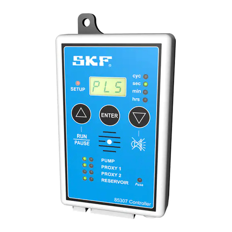
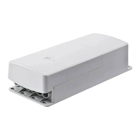
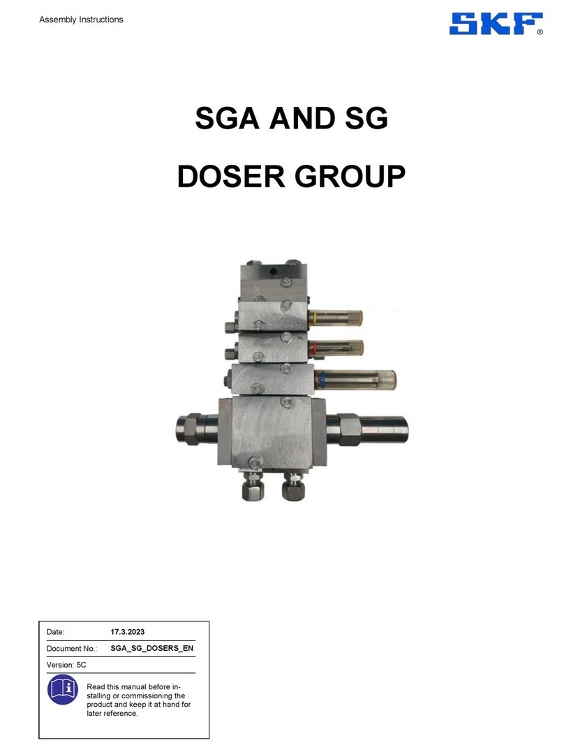
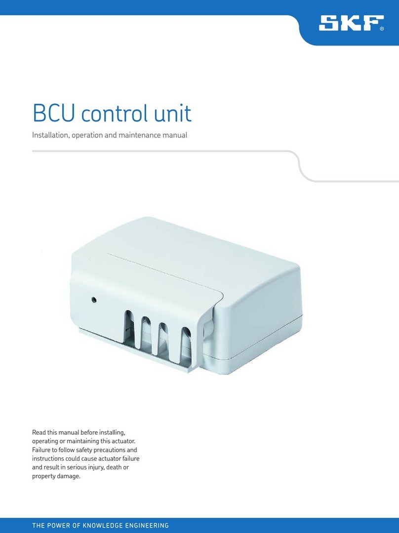
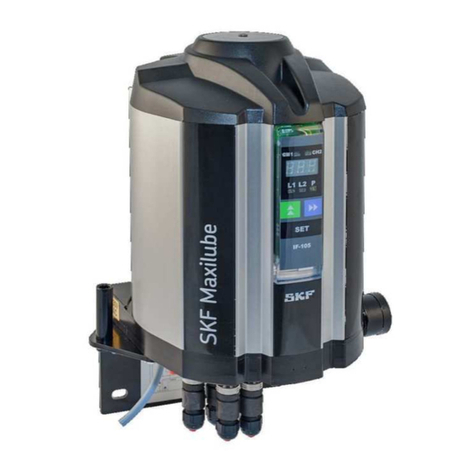
SKF LCG2-A Series User manual

EN
Curve Sensor Control Units
of Series LCG2-A/LCG2-B
Operating instructions
Version 05
for the control of centralized lubrication systems in rail vehicles

Page 2
EN Notes
Masthead
These operating instructions pursuant to EC
MachineryDirective 2006/42/EC are an integral
part of the described product and must be
kept for future use.
These operating instructions have been pre-
pared in accordance with the established stan-
dards and rules for technical documentation,
VDI 4500 and EN 292.
© SKF Lubrication Systems Germany GmbH
This documentation is protected by copyright.
SKF Lubrication Systems Germany GmbH re-
serves all rights, including those to the photo-
mechanical reproduction, duplication, and dis-
tribution by means of special procedures (e.g.,
data processing, data media, and data net-
works) of this documentation in whole or in
part.
Subject to changes in contents and technical
information.
Service
If you have technical questions, please contact
the following addresses:
SKF Lubrication Systems Germany GmbH
Berlin Plant
Motzener Strasse 35/37
12277 Berlin
Germany
Tel. +49 (0)30 72002-0
Fax +49 (0)30 72002-111
www.skf.com/lubrication
Hockenheim Plant
2. Industriestrasse 4
68766 Hockenheim
Germany
Tel. +49 (0)62 05 27-0
Fax +49 (0)62 05 27-101
www.skf.com/lubrication

Page 3 EN
Table of contents
Table of contents
Information concerning Declaration of
Conformity 4
Explanation of symbols and signs5
1. Safety instructions 6
1.1 Intended use 6
1.2 Authorized personnel 7
1.3 Electric shock hazard 7
1.4 System pressure hazard 7
2. Transport, delivery, and storage 8
2.1 General information 8
2.2 Electronic and electrical devices 8
2.3 General notes 8
3. Overview of device series 10
3.1 Distinguishing features 10
3.2 LCG2-A (24 V DC design) 10
3.3 LCG2-B (72 V DC to 110 V DC design) 12
4. Design and function 14
4.1 Design 14
4.2 Function 16
4.2.1 Curve sensor special mode 17
4.2.2 Curve-dependent spraying/calibration 18
4.2.3 Curve-dependent spraying,
outside curve 19
4.2.4 Curve-dependent spraying,
both sides 19
4.2.5 Setting spray interval time tPfor curve-
dependent spraying 19
4.2.6 Time- or distance-dependent spraying 20
4.2.7 Time-dependent spraying 21
4.2.8 Distance-dependent spraying 22
4.2.9 Setting the spray time tS 23
4.2.10 Setting the pulse voltage range on
LCG2-B 23
4.3 Spray valve actuation based on curve
direction and direction of travel 24
5. Assembly 25
5.1 General information 25
5.2 Setup and installation 25
5.3 Installation of LCG2-A and LCG2-B
curve sensor control units 26
5.3.1 Mounting equipment 26
5.3.2 LCG2-A mounting diagram 27
5.3.3 LCG2-B mounting diagram 28
5.4 Electrical connection 28
5.5 Customer connection of LCG2-A 29
5.6 Customer connection of LCG2-B 30
5.6.2 Electrical connection illustration
LCG2-A01; LCG2-A02; LCG2-A03 31
5.6.3 Electrical connection illustration
LCG2-B01; LCG2-B02; LCG2-B03 33
5.7 Curve function of LCG2-A01/B01
curve sensors 35
5.7.1 Using curve sensor LCG2-A01/ B01 36
5.7.2 Using curve sensor
LCG2-A02/A03/B02/B03 37
6. Operation 38
6.1 Adjustment elements of the curve
sensor control units 38
6.2 Operating modes of curve sensor control
units LCG2-A01, -A02, -B01, -B02 41
6.2.1 Curve-dependent spraying
LCG2-A01, -A02, -B01, -B02 42
6.2.2 Time-dependent spraying
LCG2-A01, -A02, -B01, -B02 43
6.2.3 Time- and curve-dependent spraying
LCG2-A01, -A02, -B01, -B02 44
6.2.4 Distance-dependent spraying
LCG2-A01, -A02, -B01, -B02 45
6.2.5 Distance- and curve-dependent spraying
LCG2-A01, -A02, -B01, -B02 46
6.3 Operating modes of curve sensor
control units LCG2-A03, -B03 47
6.3.1 Curve-dependent spraying 47
6.3.2 Time-dependent spraying 48
6.3.3 Time- and curve-dependent spraying 49
6.3.4 Distance-dependent spraying 50
6.3.5 Distance- and curve-dependent
spraying 51
7. Commissioning 52
7.1 Commissioning procedure 52
8. Decommissioning and disposal 52
8.1 Temporary shutdown 52
8.2 Permanent shutdown 52
9. Maintenance and service 53
10. Operational malfunctions 54
10.1 General information 54
10.2 Troubleshooting 54
11. Technical data 59
11.1 General characteristics 59
11.2 Electrical characteristics 63

Page 4
EN
The product “curve sensor control device” of
the series
is hereby confirmed to comply with the re-
quirements of the following standard:
DIN EN 50155:2008-03
Railway applications - Electronic equipment
used on rolling stock
See the appendix to the Declaration of
Conformity for the operating conditions under
which the product complies with the standard
DIN EN 50155:2008-03.
Notes:
Information concerning Declaration of Conformity
The product is neither designed nor approved
for use in conjunction with fluids of Group 1
(Dangerous Fluids) as defined in Article 2, Para.
2 of Directive 67/548/EEC of June 27, 1967.
The product is neither designed nor approved
for use in conjunction with gases, liquefied gas-
es, pressurized gases in solution, vapors, or
such fluids whose vapor pressure exceeds nor-
mal atmospheric pressure (1013 mbar) by
more than 0.5 bar at their maximum permis-
sible temperature.
When used in conformity with their intended
use, the products supplied by SKF Lubrication
Systems Germany GmbH do not reach the limit
values listed in Article 3, Para. 1, Clauses 1.1 to
1.3 and Para. 2 of Directive 97/23/EC. They are
therefore not subject to the requirements of
Annex 1 of the Directive. Consequently, they do
not bear a CE marking in respect of Directive
97/23/EC. SKF Lubrication Systems Germany
GmbH classifies them according to Article 3,
Para. 3 of the Directive.
The Declaration of Conformity forms part of
the product documentation and is supplied
together with the product.
(a) This declaration certifies compliance with
the aforementioned standards, but does not
constitute a guarantee of characteristics.
(b) The safety instructions in the documenta-
tion included with the product must be
observed.
(c) The commissioning of the products here
certified is prohibited until the machine,
vehicle, or similar in which the product is
installed conforms with the provisions and
requirements of the applicable Directives.
(d) The operation of the products at non-stan-
dard supply voltage, as well as non-adher-
ence to the installation instructions, can
negatively impact the EMC characteristics
and electrical safety.
We further declare:
The aforementioned product is, according
to EC Machinery Directive 2006/42/EC,
Annex II Part B, designed for installation in
machinery/for incorporation with other
machinery to form a machine. Within the
scope of application of the EC Directive,
commissioning shall be prohibited until the
machinery in which this part is installed
conforms with the provisions of this
Directive.
The aforementioned product may, with ref-
erence to EC Directive 97/23/EC concern-
ing pressure equipment, only be used in
accordance with its intended use and in
conformity with the instructions provided
in the documentation. The following must
be observed in this regard:
LCG2-A..., LCG2-B...

Page 5 EN
Indicators used with safety instructions
and their significance
Explanation of symbols
Explanation of symbols and signs
the environment, next to all safety instructions
in these operating instructions.
Please heed these instructions and proceed
with special care in such cases. Please forward
all safety instructions to other users.
Signal word meaning
Danger! Danger of bodily
injury
Warning! Danger of damage to
property and
the environment
Note! Provides additional
information
Instructions placed directly on the machines/
grease lubrication pump units, such as:
Rotation arrows
must be followed and kept in fully legible
condition.
You are responsible!
Please read the assembly and operating
instructions thoroughly and follow the safety
instructions.
Hazard symbols
General hazard
DIN 4844-2-W000
Electrical voltage/current
Hot surface
Electrostatic sensitive components
DIN 4844-2-W008
DIN 4844-2-W026
Slipping hazard
DIN 4844-2-W028
Informational symbols
Note
Prompts an action
Used for itemizing
Refers to other facts,
causes, or consequences
Provides additional information
Environmentally correct disposal

Page 6
EN 1. Safety instructions
The operator of the described prod-
uct must ensure that the operating
instructions are read and understood
by all persons responsible for assembly,
operation, maintenance, and repair of
the product. The operating instructions
must be kept readily available.
Note that the operating instructions
form part of the product and must
accompany the product if sold to a new
owner.
1. Safety instructions
In addition to the operating instructions,
statutory regulations and other general
regulations for accident prevention in
the railway sector (railway regulations)
and environmental protection must be
observed and applied.
The described product is manufactured in ac-
cordance with the generally accepted rules and
standards of industry practice and with occu-
pational safety and accident prevention regu-
lations. Risks may, however, arise from its us-
age and may result in physical harm to
persons or damage to other material assets.
Therefore the product may only be used in
proper technical condition and in observance
of the operating instructions. In particular, any
malfunctions which may affect safety must be
remedied immediately.
1.1 Intended use
The LCG2-Axx and LCG2-Bxx curve sensor
control units are used exclusively to control
centralized lubrication systems in rail vehicles.
They are not suitable for handling safety-re-
lated functions or for detecting curves in con-
nection with railway tilting systems. They are
likewise unsuitable for use in aviation systems
or for navigation in any type of vehicle or
ships.
Any other usage is deemed non-compliant
with the intended use.
Hazardous materials of any kind, especially
the materials classified as hazardous by CLP
Regulation EC 1272/2008 may only be used
to fill SKF centralized lubrication systems and
components and deliv-ered and/or distributed
with the same after consulting with and re-
ceiving written approval from SKF.
The described products are neither designed
nor approved for use in conjunction with gas-
es, liquefied gases, pressurized gases in solu-
tion, vapors, or such fluids whose vapor pres-
sure exceeds normal atmospheric pressure
(1013 mbar) by more than 0.5 bar at their
maximum permissible temperature.
Unless specially indicated otherwise, products
from SKF Lubrication Systems Germany
GmbH are not approved for use in potentially
explosive areas as defined in the ATEX
Directive 94/9/EC.

Page 7 EN
1. Safety instructions
1.2 Authorized personnel
Only qualified technical personnel may install,
operate, maintain, and repair the products de-
scribed in the operating instructions. Qualified
technical personnel are persons who have
been trained, assigned, and instructed by the
operator of the final product into which the
described product is incorporated. Such per-
sons are familiar with the relevant standards,
rules, accident prevention regulations, and as-
sembly conditions as a result of their training,
experience, and instruction. They are autho-
rized to identify and perform necessary ac-
tions while avoiding any risks which may arise.
The definition of qualified personnel and the
prohibition against employing non-qualified
personnel are laid down in DIN VDE 0105 and
IEC 364.
1.3 Electric shock hazard
Electrical connections for the described prod-
uct may only be established by qualified and
trained personnel authorized to do so by the
operator in observance of the local electrical
operating conditions and local regulations (e.g.,
DIN, VDE). Serious injury or death and prop-
erty damage may result from improperly con-
nected products.
Danger!
Performing work on an energized
pump or product may result in serious
injury or death.
Assembly, maintenance, and repair
work may only be performed on prod-
ucts that have been de-energized by
supply voltage must be switched off
before opening any of the product's
components.
1.4 System pressure hazard
Danger!
Lubrication systems are pressurized
during operation. Centralized lubrication
systems must therefore be depressur-
ized before starting assembly, main-
tenance or repair work, or any system
Danger!
Do not spray people or animals with
lubricants.

Page 8
EN
2. Transport, delivery, and storage
2.1 General information
SKF Lubrication Systems Germany GmbH
products are packaged in accordance with
standard commercial practice according to the
regulations of the recipient's country and DIN
ISO 9001. During transport, safe handling
must be ensured and the product must be
protected from mechanical effects such as im-
pacts. The transport packaging must be
marked "Do not drop!".
There are no restrictions for land, air, or sea
transport.
After receipt of the shipment, the product(s)
must be inspected for damage and for com-
pleteness according to the shipping docu-
ments. The packaging material must be pre-
served until any discrepancies are resolved.
SKF Lubrication Systems Germany GmbH
products are subject to the following storage
conditions:
Ambient conditions: Dry and dust-free
surroundings, storage in well
ventilated dry area
Storage time: Max. 24 months
Permissible humidity: < 65%
Storage temperature: -40 °C to +85 °C
Light: Avoid direct sun or UV exposure
and shield nearby sources of heat
2.3 General notes
The product(s) can be enveloped in plastic
film to provide low-dust storage.
Protect against ground moisture by
storing on a shelf or wooden pallet.
At approx. 6-month intervals: Check for
corrosion. If there are signs of corrosion,
reapply anti-corrosive agents.
2.2 Electronic and electrical devices

Page 9 EN

Page 10
EN 3. Overview
Components of the LCG2-A control unit series, Fig. 1
3. Overview of device series
2
0
E
6
.
.
.
C
.
A
.
8
.
.
.
4
4132ONECE5678
X110987654321141617181519111312
123456789
3.1 Distinguishing features
The major features distinguishing the LCG2-A
and LCG2-B series are operating voltages,
system design, and housing dimensions. Both
series are available in three software versions:
LCG2-A 01
LCG2-A 02
LCG2-A 03
LCG2-B 01
LCG2-B 02
LCG2-B 03
(See Chapter 4.1, Table 1)
The software versions differ in terms of actua-
tion of valve outlets A1 and A2 depending on
the curve direction and direction of travel as
well as in terms of the adjustment options for
spray and interval times (see Chapter 4.2,
Table 2).
3.2 LCG2-A (24 V DC design)
Shown without cover

Page 11 EN
3. Overview
Legend to Fig. 1, Components and function of LCG2-A control unit
Item Component Function
1 LED, green Output A1 Valve output A1 (activated)
2 LED, green Output A2 Valve output A2 (activated)
3 LED, yellow Input FG Spray enable (activated)
4 LED, yellow Input VR Direction of travel 2 (activated)
5 LED, yellow Input DK Pushbutton DK (manual spray cycle triggering)
6 LED, yellow Input +P Distance pulse signal, logical 1
7 LED, green Operating voltage Operating voltage connected
8 LED, red Reset Trigger program restart (temporary signal)
9 Programming interface
10 DIP switches 1 to 8 System configuration Configuration of functional parameters
11 Rotary switch (16-position) Curve sensor configuration Sensor activation and sensitivity configuration
12 Sensor circuit board
13 Main circuit board
14 LED, red Program start Initialization complete (temporary signal)
15 LED, yellow Program start Initialization complete (temporary signal)
16 LED, green Input +P/-P Frequency-dependent spray enable
17 Pushbutton DK Manual spray cycle triggering
18 Electrical plug connector X1 Socket for customer wiring
19 Protective earth connector PE Socket for customer wiring

Page 12
EN 3. Overview
Components of the LCG2-B control unit, Fig. 2
3.3 LCG2-B (72 V DC to 110 V DC design) 12
-A1+A1-A2+A2
PEML+4132ON5678
0
F
E
D
C
B
A
9
8
7
6
5
4
3
2
1
FGVRDK+P-P5678910111213141516171819202112342223Shown without cover

Page 13 EN
3. Overview
Legend to Fig. 2, Components and function of LCG2-B control unit
Item Component Function
1 Electrical plug connector X1 Valve outputs (PE conductor) Socket for customer wiring
2 Electrical plug connector X2 Operating voltage input Socket for customer wiring
3 Electrical plug connector X3 Valve outputs Socket for customer wiring
4 Electrical plug connector X4 Control inputs Socket for customer wiring
5 LED, green Output A1 Valve output A1 (activated)
6 LED, green Output A2 Valve output A2 (activated)
7 LED, yellow Input FG Spray enable (activated)
8 LED, yellow Input VR Direction of travel 2 (activated)
9 LED, yellow Input DK Pushbutton DK (manual spray cycle triggering)
10 DIP switches 9 and 10 Voltage range for input +P/-P Adjustment to distance pulse generator
11 LED, yellow Input +P Distance pulse signal, logical 1
12 LED, green Operating voltage Operating voltage connected
13 LED, red Reset Trigger program restart (temporary signal)
14 LED, yellow Input +P Distance pulse signal, logical 0
15 Rotary switch (16-position) Curve sensor configuration Sensor activation and sensitivity configuration
16 DIP switches 1 to 8 System configuration Configuration of functional parameters
17 Pushbutton DK Manual spray cycle triggering
18 LED, green Input +P/-P Frequency-dependent spray enable
19 LED, yellow Program start Initialization complete (temporary signal)
20 LED, red Program start Initialization complete (temporary signal)
21 Programming interface
22 Main circuit board
23 Sensor circuit board

Page 14
EN 4. Design and function
Table 1
LCG2-Axx-XXX+924 LCG2-Bxx-XXX+902
Rated operating voltage 24V DC 72 V to 110 V DC
Housing dimensions (width x height x
depth)
(without cable glands and pushbutton DK)
(80 x 125 x 58) mm
See Fig. 6
(200 x 140 x 91) mm
See Fig. 7
Design See Fig. 1 See Fig. 2
Electrical connection diagram See Fig. 10 See Fig. 11
Software versions 01, 02, 03 01, 02, 03
4. Design and function
The LGC2-A and LCG2-B curve sensor control
units are used to control wheel flange and
railhead lubrication systems. In these systems,
the lubricant is sprayed through spray nozzles
onto the wheel flange of the rail vehicle or
onto the head of the rail. The term "spraying"
is therefore used in the description below.
As can be seen from the control units' electri-
cal connection diagrams, the compressed air
valves Y1 and Y2 are always connected via
outputs A1 and A2. Where appropriate for
clarity, the following description only mentions
the corresponding valve, Y1 or Y2.
Additionally, for the sake of clarity the follow-
ing text only indicates the software version
numbers 01, 02, and 03 from the device or-
der code (e.g., LCG2-Axx-XXX+924 or LCG2-
Bxx-XXX+902) because the corresponding
functions of the LCG2-A and LCG2-B series
are identical.
4.1 Design
The significant differences between the
LCG2-A and LCG2-B series are in their hous-
ing dimensions, their design, and their operat-
ing voltage. Both series are available with
software versions 01, 02, or 03.

Page 15 EN
4. Design and function
Legend to Fig. 3, see page 40 for further information
Rotary switch (see Chapter 4.2.2 for description and Chapter 6 for settings)
Deactivation, activation, and sensitivity setting of curve sensor
DIP switches 1 to 8
Settings for operating mode and other functional parameters
S-1 - Preselection for time- or distance-dependent spraying
S-2 - Curve sensor special mode
S-3 - Sets spray interval time tp for curve-dependent spraying
(only on software versions 01 and 02)
- Sets spray time ts
(only on software version 03)
S-4 - Sets spray interval time tp for curve-dependent spraying
S-5 to - Deactivates or activates operating mode preselected with DIP-1
S-8 by configuring the spraying duration for time- or
distance-dependent spraying
DIP switches 9 to 10 (see Chapter 6 for settings)
Switches voltage range of distance pulse input +P/-P(only on LCG2-B)
DK button
- Manually triggers a spray cycle
- Manually triggers a series of spray cycles to vent the lubricant lines
(e.g., during commissioning; see page 39, Table 3)
Adjustment elements of LCG2-A, LCG2-B, Fig. 3
12ON
-A1+A1-A2+A2
PEML+4132ON5678
0
F
E
D
C
B
A
9
8
7
6
5
4
3
2
1
FGVRDK+P-PX1X2X3X4
0
F
E
D
C
B
A
9
8
7
6
5
4
3
2
1
4132ON5678
2
0
E
6
.
.
.
C
.
A
.
8
.
.
.
4
4132ONECE5678
4132ON5678
0
F
E
D
C
B
A
9
8
7
6
5
4
3
2
1
910ON
DK button
Rotary switch
DIP switches
1-8
DK button
DIP
switches
1-8
Rotary switch
DIP switches
9-10
LCG2-A
LCG2-B

Page 16
EN 4. Design and function
Table 2
Chapter Operating modes/features Software versions
01 02 03
4.2.1 Curve sensor special mode
4.2.2 Curve-dependent spraying
4.2.3 Curve-dependent spraying, outside curve (left or right)
4.2.4 Curve-dependent spraying, both sides (left and right)
4.2.5 Adjustable spray interval time for curve-dependent spraying
4.2.7 Time-dependent spraying
Time- and curve-dependent spraying
4.2.8 Distance-dependent spraying
Distance- and curve-dependent spraying
4.2.9 Adjustable spray times
Spray times for single-line system
Spray times for dual-line system
4.2 Function

Page 17 EN
4. Design and function
4.2.1 Curve sensor special mode
DIP switch 2
= OFF: Curve sensor control function
(factory setting)
DIP switch 2
= ON: Curve sensor special mode
After switching to the curve sensor's special
mode, the device functions as a "pure" curve
sensor in that a continuous signal instead of a
spray cycle signal is issued on the respective
valve output (A1 or A2) as long as a curve is
being traveled and the preset curve signal
threshold is exceeded (for the sensitivity set-
ting, see Table "D" for the respective software
version (01, 02, or 03) as well as operating
mode "Curve-dependent spraying").
No further enabling signal is required to issue
the continuous signal. This function is, how-
ever, only intended for an application in which
all other functions are handled by another
control unit, for example a stored-program
controller (SPC) already installed in the vehi-
cle, or the SKF IG665+924 control unit (only
available in 24 V DC), which comes with addi-
tional functions beyond the control unit mod-
els described here, such as compressor control
for compressed air generation (control and
monitoring), lubricant monitoring (fill level and
pressure), special lubricant pump control, etc.
The DK pushbutton and the FG, VR, DK,
and +P/-P control inputs, as well as DIP
switches 1 and 3 to 8, have no function
in the curve sensor's special mode.
The setting for DIP switch 2 is read and
processed by the control unit only after
a program restart.
4132
5678
DIP switches, Fig. 4

Page 18
EN 4. Design and function
The curve sensor control units feature an in-
ternal sensor that directly detects the turning
motion of the rail vehicle as it travels through
a curve. The control unit evaluates the sensor
signal; if an adjustable signal threshold is ex-
ceeded and the spray enable conditions are
met, a spray cycle is triggered via the corre-
sponding spray valve (Y1 or Y2). The spray
valve cycles when there is an extended-dura-
tion curve signal (see adjustable spray interval
time in 4.2.5 and spray time in 4.2.9).
Spray enable condition when using curve-de-
pendent spraying:
• Enable input FG connected
(switching contact FG closed)
Spray enable condition when using curve- and
time-dependent spraying:
• Enable input FG connected
(switching contact FG closed)
Spray enable conditions when using curve-
and distance-dependent spraying:
• Enable input FG connected
(switching contact FG closed)
and
• Pulse frequency at input +P/-P is
greater than 3.5 Hz (minimum travel speed
has been reached)
If only curve-dependent spraying is to be per-
formed, the setting for DIP switch 1 must also
be considered (see Spray enable conditions in
4.2.6).
The curve sensor function is activated (switch
settings 1 to F) and deactivated (switch setting
0, factory setting) on the rotary switch.
The sensitivity of the curve sensor can be set
(in angular degrees per second) using switch
settings 1 to F as shown in the "D" tables in
Chapter 6 for the respective software version
(01, 02, or 03) as well as operating mode
"Curve-dependent spraying."
If a time- or distance-dependent spray cycle is
ongoing when a curve is detected, the spray
cycle continues until completion. The curve-
dependent spray cycle is eliminated or
overridden.
Each time the operating voltage is switched
on, a waiting period of 6 seconds is required
for the automatic "curve zeroing" before the
vehicle is moved.
Based on the type of curve sensor
employed, the curve sensor control de-
on statistical average yield a straight
line,i.e., the distribution of left and right
curves must be approximately equal.
A microcontroller generates a moving
median value from the sensor param-
eters for the straight lines and curves
traveled. This value is used for continu-
ous adjustment of the reference angular
velocity of 0 degrees/s.Aging and tem-
are also compensated for.
4.2.2 Curve-dependent spraying/calibration

Page 19 EN
4. Design and function
4.2.3 Curve-dependent spraying,
outside curve
(software version 01)
In software version 01, only the spray nozzle
(left or right) outside the curve is actuated
during curve-dependent spraying. Each of the
two spray nozzles is activated via a separate
valve, Y1 or Y2. If the vehicle is operated in
two directions, direction of travel input VR on
the control unit must be connected (switching
contact VR closed) when the vehicle moves in
direction of travel 2 so that the spray nozzle
outside the curve can be actuated in this situ-
ation (see Curve function, Fig. 5).
4.2.4 Curve-dependent spraying,
both sides
(software versions 02 and 03)
In software versions 02 and 03, only valve Y1
is actuated during curve-dependent spraying
in both curve directions; the valve then acti-
vates both spray nozzles (left and right). If the
vehicle is operated in two directions, direction
of travel input VR on the control unit does not
necessarily need to be connected when the
vehicle moves in direction of travel 2. If, how-
ever, spray nozzles on the other end of the
vehicle are to be actuated, all spray cycles can
be directed to valve Y2 by connecting direction
of travel input VR (switching contact VR closed)
(see Curve function, Fig. 5).
4.2.5 Setting spray interval time tPfor
curve-dependent spraying
(software versions 01 and 02)
The spray interval time tP for curve-dependent
spraying is set using DIP switches 3 and 4 (see
Table B on page 42).
(software version 03)
The spray interval time tP for curve-dependent
spraying is set using DIP switch 4 (see Table B
on page 47).
Note
Setting the curve-dependent spray interval
time tP also defines the following times:
In software versions 01, 02, 03:
Minimum possible interval time for dis-
tance-dependent spraying if, for example,
an excessively low number of pulses was
preselected for the cycle duration.
Only in software version 01:
Spray interval time tP when using time- or
distance-dependent spraying between spray
times tS of valves Y1 and Y2, which are ac-
tuated sequentially in this operating mode.

Page 20
EN 4. Design and function
4.2.6 Time- or distance-dependent spraying
The operating modes and all other functional
parameters are set using DIP switches 1 to 8
in accordance with the corresponding tables in
Chapter 6 of these operating instructions.
DIP switch 1 defines a preselection for the fol-
lowing operating modes:
DIP switch 1
= OFF: Time-dependent spraying
(factory setting)
DIP switch 1
= ON: Distance-dependent spraying
The preselected operating mode is only effec-
tively activated once at least one of the DIP
switches from 5 to 8 is switched to the ON
position.
If only curve-dependent spraying is to be per-
formed, DIP switches 5 to 8 remain in the OFF
position (factory setting).
Spray enable conditions
Setting DIP switch 1 also defines the spray
enable conditions irrespective of whether the
preselected operating mode is activated using
DIP switches 5 to 8:
DIP switch 1
= OFF: Spray enable only via input FG
(factory setting)
DIP switch 1
= ON: Spray enable via input FG and
minimum pulse frequency on input
+P/-P
Spray cycle triggering in software version 01
A time- or distance-dependent spray cycle is
performed in the sequence:
Spray time tS for valve Y1 - spray interval time
tP - spray time tS for valve Y2 – spray interval
time ≥ tP.
Spray cycle triggering in software versions
02 and 03
A time- or distance-dependent spray cycle is
triggered based on the connection of direction
of travel input VR:
Switching contact VR = open:
Spray time tS for valve Y1 – spray interval
time ≥ tP
Switching contact VR = closed:
Spray time tS for valve Y2 – spray interval
time ≥ tP
This manual suits for next models
7
Table of contents
Other SKF Control Unit manuals
Popular Control Unit manuals by other brands

Madas
Madas M16/RM N.C. DN 65 EEX manual

XIAMEN OCULAR
XIAMEN OCULAR GDM12864A user guide

Sundance Spas
Sundance Spas SMT351 user manual

Radio Shack
Radio Shack Color Graphics Option installation instructions

AUDAC
AUDAC APC100 MK2 user manual

Kerotest
Kerotest EV-11 Installation, operation and maintenance manual

YASKAWA
YASKAWA JEPMC-OP3C01-E instructions

Vortice
Vortice CR5N Instruction booklet

GOK
GOK Caramatic ProTwo Assembly and operating manual

Simplex
Simplex Foundation Series Operation guide

Lutron Electronics
Lutron Electronics QSGRK-6D Quick installation and operation guide

Skipper
Skipper SB-100-SA Installation and operation manual