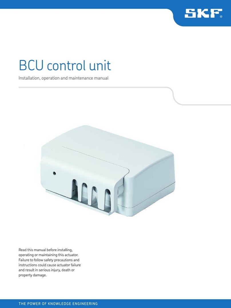
SKF SCU 1 User manual

SCU
Control unit
Read this manual before installing, operating
or maintaining this actuator. Failure to follow
safety precautions and instructions could
cause actuator failure and result in serious
injury, death or property damage.
Installation, operation
and maintenance manual

2
L5318,2970E.1/09.10 6HSWHPEHUWK
® SKF is a registered trademark of the SKF Group
© SKF 2010
The contents of this publication are the copyright of the publisher and may not be reproduced (even extracts) unless
prior written permission is granted. Every care has been taken to ensure the accuracy of the information contained
in this publication but no liability can be accepted for any loss or damage whether direct, indirect or consequential
arising out of the use of the information contained herein

3
L5318,2970E.1/09.10
Basic Principles ....................................................................................................4
1 Introduction ............................................................................................................4
Operation manual..................................................................................................4
Organizational measures ......................................................................................5
Conventions ............................................................................................................6
2 Safety.......................................................................................................................7
Safety program ......................................................................................................7
Other hazards.........................................................................................................9
3 Construction and function ....................................................................................11
Construction ...........................................................................................................11
Function...................................................................................................................12
Options and accessories .......................................................................................14
Normal Operation ................................................................................................16
4 Normal operation...................................................................................................16
Preconditions for operation..................................................................................16
SCU control unit powering on .............................................................................17
SCU control unit shutting down ..........................................................................17
Operating processes..............................................................................................18
Special operations ...............................................................................................20
5 Installation and Initial start-up............................................................................20
Preparation .............................................................................................................20
Installation and connections.................................................................................21
Initial start-up ........................................................................................................24
6 Maintenance, clearing malfunctions, repairs.....................................................26
Maintenance ...........................................................................................................26
Malfunctions ...........................................................................................................26
Repair ......................................................................................................................29
7 Removing from service, dismantling and disposal ...........................................30
Shutting down........................................................................................................30
Dismantling.............................................................................................................30
Storage....................................................................................................................30
Disposal...................................................................................................................31
Appendix.................................................................................................................32
8 Appendix..................................................................................................................32
Technical data.........................................................................................................32
Plans and diagrams...............................................................................................33
Standards applied..................................................................................................35
Table of contents
i
4
L5318,2970E.1/09.10
This chapter contains information on the organization and structure of the operation
manual. It makes the operation manual easier to handle and enables quick access to
the desired information.
The following chapters are part of the basic principles:
n1. Introduction, page 4
n2. Safety, page 7
n3. Construction and Function, page 11
SKF Actuation System manufactures state-of-the-art electric actuators, control
units and operating equipment.
The purpose of this operation manual is to introduce you, as the user and the entity
doing the further processing, to correct utilization and safe use.
For this goal to be achieved, it is essential that you very carefully read the chapter on
safety (2. Safety, page 7) and follow the instructions in this manual.
Validity
The instructions in this manual refer to the linear actuator SCU control unit with the
following identification:
nManufacturer: SKF Actuation System (Liestal) AG
nProduct name: SCU control unit
nType designation: SCUxx-xxxxxx-xxxx
nYear of manufacture: from 2006
nCE Mark: according to technical documentation
nSerial number: from L04330000
Target audience and obligation to read
The operating manual is intended for technical personnel and authorized users who use
the SCU control unit in their products and work with them. The operating authority
determines who is authorized as a user.
We distinguish between different user groups, as the requirements on the users vary,
depending on the activity they perform.
Please note: You can find definitions of user groups along with their corresponding
requirements in the chapter on safety (2. Safety, page 7). You can assume one or
more of these user groups provided you meet the applicable requirements.
1. Introduction
Basic principles
Operation manual

5
L5318,2970E.1/09.10
The organization and implementation of the operation manual takes into account the
different user groups.
Summary of contents
The operation manual serves as a reference work. The information therein is organized
into four task- and theme-related parts:
Basic Principles The Basic Principles section gives the basic knowledge that every user should have.
Normal Operation The Normal Operation section contains information needed for operating the product
under normal conditions, i.e. undisrupted operation for use according to its intended
application.
Special Operations The Special Operations section describes all jobs deviating from normal operation, such
as installation, initial start-up, maintenance, fixing faults and doing repairs.
Appendix The Appendix contains information that the user has to be able to access at any time.
This includes information on using the operation manual (indexes) as well as data
concerning the product itself (technical data).
Aids for accessing information
This manual has access aids that make it easier for you to quickly access the
desired information:
nYou can most easily find all information on a given topic in the Table of Contents,
as a result of the task and theme-related organization of the operation manual.
nInformation on a specific activity or a special topic can be found most quickly
through the Index.
nWithin the chapters of the operation manual, you can orient yourself with the help
of the margin notes.
Introduction
Organizational measures
If you have any questions that cannot be answered through this operation manual, contact
the manufacturer directly.
Location of the operation manual
The operation manual can only benefit you if you have it available at all times. For this
reason, always keep the operation manual where the equipment is being used.

6
L5318,2970E.1/09.10
Manufacturer address Contact address
SKF Actuation System (Liestal) AG Your local SKF representative.
Oristalstrasse 97
CH-4410 Liestal
Tel.: +41 / 61 / 925 41 11
Fax: +41 / 61 / 921 37 04
E-mail: actuators.switzerland@skf.com
Introduction
Conventions In this manual we use a few abbreviations and markings to label sections of text or notes.
In the following sections you will find these conventions explained.
Warnings and usage hints
Please note the meaning of the following warnings and usage hints:
Please note: indicates usage information that helps the user to use the product
correctly and efficiently or to understand the properties of the product.
CAUTION
Caution: warning to inform the user of hazards that remain
due to the incomplete effectiveness of protective measures
for property damage or personal injury; pointer to any special
training and personal protective equipment that may
be required.
WARNING
Warning: warning of irreparable property damage or person-
al injury that remains based on hazard analysis. With
reference to protective measures and any special training
and personal protective equipment that may be required.
Position numbers and references
Position numbers We number diagram parts clockwise in serial order and unambiguously.
Cross-references to Cross-references to chapters or diagrams are given in parentheses. They contain the
text passages corresponding chapter or diagram number

7
L5318,2970E.1/09.10
This chapter targets all the users of the SCU control unit. It contains information
on its safe use and optimal utilization.
2. Safety
The safety program from SKF Actuation System spells out who is entitled to use
it and the responsibility of individual users.
The SCU control unit was designed and built in accordance with the latest technical
standards and accepted safety rules.
EU-conformity is documented with the technical documentation.
Purpose of use of the SCU control unit
The SCU control unit has been designed and constructed for use in accordance with its
intended purpose-conformant use. If you use the SCU control unit for any use other
than the use described, the manufacturer cannot be held liable for damage that results
therefrom.
Intended Use
The authorized use of the SCU control unit is to:
nControl a maximum of six actuators for pressure or tension-stressed strokes.
Please note: The control can only be parametrized for the actuators of SKF Actua-
tion System. Please contact customer services to find out which actuators
are approved for the SCU control unit (refer to Manufacturer Address, page 6).
Please note: For the operations data, please see the Appendix of this operating
manual (see Operating data, page 34).
Unauthorized use
Any use other than the intended use without the manufacturer’s written agreement or
operation beyond the technical limits is considered unauthorized.
The technical usage limits can be found in the appendix to this operation manual. Tech-
nical Data, page 33) and on the type plate of the SCU control unit.
Please note: in case of improper use of the SCU control unit, damage to persons
and property may result. Always adhere to the instructions of this manual.
Safety program

8
L5318,2970E.1/09.10
Safety
User groups
To ensure safety, we place requirements on the users of the SCU control unit that must
be adhered to under all circumstances. Only persons who meet the requirements are
entitled to use the SCU control unit.
We refer to all persons who operate, use, commission the control unit, process it further
or pass it on for further processing as user groups. As the requirements of these user
groups strongly depend on their role, we distinguish between the following user groups:
Operating Authority The operating authority is the contractual partner of the person doing the further process-
ing or the reseller. They can impose legal conditions on the operating authority when pur
chasing the control unit. The operating authority ensures that the user is instructed in the
authorized use of the equipment.
Processor The processor is the contractual partner of the reseller or the manufacturer. He assembles
the control unit into a total device. He is authorized by the manufacturer of the SCU control
unit to use the control unit in accordance with the regulations and has the necessary
expert knowledge.
Technician The technician has the professional technical training to implement the SCU control unit
according to its authorized use. Apart from the chapter on Safety, he is also familiar with
the chapter on Special operating modes. He will find the required technical data in the
Appendix.
Reseller The reseller forwards the machine.
Operator Every other person who uses the SCU control unit we define as an operator. The operator
must have read the Safety chapter in this manual before using the machine. Moreover, he
must be instructed about the normal operation by the operating authority.
Types of operation
Intermittent The SCU control unit is exclusively intended for intermittent operation
(see Technical Data, page 33).
Danger zones
We differentiate between two danger zones that must be observed, depending on
user role.
Persons The danger zone covering persons also includes, in addition to the actual user, third per-
sons
(other personnel, visitors, patients etc.). In case of injury, the operating authority is liable.
Device The danger zone device comes under the user group Executor and Technician and covers
the SCU control unit and all the mounted-on devices.

9
L5318,2970E.1/09.10
Areas of responsibility
Different areas of responsibility, corresponding to the different user groups, arise.
Operating Authority The Operating Authority has the responsibility for the danger zone covering Persons and
ensures that only authorized and instructed users work with the SCU control unit. He or
she is responsible for the following:
nDetermining the persons who may use the SCU control unit (authorized persons)
nInstruction of the users
nComplying with all relevant legal conditions and regulations
Please note: The Operating Authority may only authorize such persons for using the SCU
control unit, who conform to the requirements for the user roles.
Processor The processor is responsible for the following:
nGeneration of a CE-conformant operation manual of the device in which the SCU
control unit has been integrated
nAdherence to the safety regulations in accordance with this operating manual
Reseller The reseller is responsible for the following:
nPassing on this operating manual and the SCU control unit to the executor or the
nPassing on of a CE-conformant operating manual and the device in which the SCU
control unit has been integrated to the Operating Authority.
Technician The technician is responsible for the following:
nObserving the manufacturer’s instructions and the safe set-up of interfaces with
other equipment.
nInstallation and use of the SCU control unit in accordance with its intended purpose-
conformant use
nInstallation of optional modules and connecting cables
Operator The operator ensures that nobody is endangered owing to the operation of the SCU control
unit. He or she is, in particular, responsible for:
nOperation of the SCU control unit in normal operation
nImmediate and appropriate reaction to malfunctions
General safety notice
The SCU control unit is only suitable for interior applications and must not be subjected to
weathering, strong UV radiation or corrosive or explosive air (see Ambient conditions,
page 34 in the 8. Appendix, page 33).
The SCU control unit may only be operated with the safety protective cover closed.
Safety

10
L5318,2970E.1/09.10
Safety
The manufacturer has constructively, and with protective measures, minimized the effects
of existing residual hazards. Pay attention to the residual hazards and the potential coun-
termeasures given in the following chapters.
Residual hazards to people, objects and property
Keep in mind the following residual dangers and the possible countermeasures in handling
the SCU control unit:
Other hazards
WARNING
Warning regarding electrical shock owing to damaged plugs
or damaged network cables. Never touch a damaged network
plug or a damaged network cable when the SCU control unit
is running, since the SCU control unit are supplied 120 VAC
or 230 VAC.
•Ensure,beforeyoupulladefectiveplugoutoftheplugsocket, that the current fuse is cut off.
•Checkthepowercableregularlyfordamage.CAUTION
Please be aware of damage to people or property as the re-
sult of incorrect operation. Incorrect operation can endanger
people in the danger zone or objects.
•Beforepressingabuttonontheoperatingunitensurethat you press the right button.
•Takeappropriatemeasurestoensurethattheoperatingunit can not be operated unintentionally.
CAUTION
Take care not to damage the SCU control unit from water
jets. The SCU control unit is protected against spraying water
according to IPX4, but not against water jets. Prevent the
SCU control unit from being subjected to water jets.

11
L5318,2970E.1/09.10
This chapter targets all the users of the SCU control unit. It shows its construc-
tion and explains its function.
3. Construction and function
The following figures will give you an overview of the SCU control unit, its connections
and operating devices.
Overall view and connections SCU control unit
Fig. 3-1 Overall view SCU control unit from above with under-floor rechargeable
battery, without safety protective cover (in image: DC design with connection cable)
1 Housing
2 Space for software data label
3 Connection for operating elements (sockets 8, 9, 10)
4 Connection for 4 external end switches (socket 7)
5 Fastening for safety protective cover
6 Cable guides
7 Installation holes (4)
Construction
1
2
16
15
14
13
12
11
10
6
3
4
5
7
8
9

12
L5318,2970E.1/09.10
Construction and function
8 Under-floor rechargeable battery
9 Connection for operating elements (sockets 1 to 6)
10 Not occupied (sockets 15, 16)
11 Not occupied (socket 14)
12 Optional rechargeable battery connection (socket 13)
13 Operational voltage indicator (not visible on this image)
14 Communication interface (socket 12)
15 Operational earthing bolt (not visible on this image)
16 Mains connection or connection for source of DC voltage (socket 11)
Fig. 3-2 Side view with under-floor rechargeable battery and closed
safety protective cover
17 Safety protective cover
18 Locking button for safety protective cover
Operating elements
Following operating elements are suitable for the SCU control unit:
nEHA 3, manual switch
nSTJ, foot switch
nSTE, table switch
The description of the function will make it possible for you to understand the tasks of
the SCU control unit, its operating devices and its options.
Please note: Please note that the functions, plug layouts and options of the con-
trol unit are configured ex-works according to the requirements and cannot be
changed subsequently.
Function
1
8
17 18

13
L5318,2970E.1/09.10
Construction and function
Functional principles
The principle of functioning of the SCU control unit is based on controlling a maximum
of six connected actuator units. The functions present in the control program are actuated
by means of manual switches or other operating devices. The SCU control unit is
configured by the manufacturer.
The SCU control unit must be equipped with one operating device and at lease one actua-
tor
unit. The DC design requires a source of DC voltage.
Operating voltage The operating voltage indicator (see position 13, Fig. 3-1, page 11) indicates whether
indicator the device is being supplied energy.
Failsafe safety In the standard configuration the SCU control unit is failsafe. Here the device checks
safety-relevant electronic system parts and if a defect occurs moves to the safe status
in which no actuator movements are possible until the defect has been removed (refer
to Malfunctions, page 26). The maximum error tolerance period is one second.
Please note: If a connected actuator does not have an internal end switch or an
internal thermo-switch this reduces the system’s failsafe system. Actuators without
internal end switches are switched off with over-current. If an actuator does
not have an internal thermo-switch and there is a defect, the actuator could overheat
and be damaged.
Please note: The system’s failsafe mechanism is reduced if an operating unit without
failsafe is connected.
Functional single The SCU control unit has functional single error security, i.e. the operation of the SCU
error security control unit is monitored. Apart from a few exceptions this also affects all the functions
of the SCU control unit.
DC voltage source Only for DC design: A smoothed power unit can be used as a DC voltage source. But it
must be noted that during operation (actuator is moving) the nominal voltage permitted
for the drives may not be exceeded (please note the other details in the annex). (refer to
Device Data, page 33).
Safety protective cover The safety protective cover protects the cable connections from being pulled out
accidentally.
Lock function The SCU control unit has a lock function. When using an appropriate operating unit with
corresponding functional buttons it is possible to lock or release individual control unit
functions. The signal is passed on to the control unit - the lock function of the SCU contro
unit takes on the locking or unlocking function. This ensures that there is no risk from
several operating devices used at the same time. If necessary locked functions are
indicated by a yellow LED.
Over-current cut-off The software with its integrated over-current cutoff switches off the SCU control unit in
case of overload and protects the connected actuator units. The factory must parameterize
the appropriate power-down values for the connected actuator.
Overtemperature The software with integrated overtemperature protects several components from over-
heating protection by stopping the running of the actuators and thus prevents the control units from being
damaged.

14
L5318,2970E.1/09.10
Construction and function
Options and accessories
Options
Options can be recognized from the type designation on the type plate.
Battery connection The SCU control unit may be fitted with a battery connection (refer to item 12, Fig. 3-1,
page 11) or a pre-installed under-floor battery. The unused battery connection is
equipped with a sealing stopper by the factory. Rechargeable batteries are available as
accessories (see Accessories, page 14).
Please note: without an external battery the connection socket must be equipped with
the factory-supplied sealing stopper for IPX4 protection to be guaranteed.
Please note the special requirements for handling rechargeable batteries. Only
batteries authorized by the manufacturer may be used.
End switches The connection for the end switch is available for all versions of the SCU control unit.
But this option must be set by the manufacturer in the factory. Here the end switches can
take on various functions. The connection socket is equipped with a sealing stopper by
the factory.
Please note: without an end switch the connection socket must be equipped with the
factory-supplied sealing stopper for IPX4 protection to be guaranteed.
Ground terminal
Accessories
Rechargeable battery The authorized batteries1) or under-floor batteries are screwed to the underside of the SCU
control unit. The SCU control unit can only be operated with a battery if the corresponding
option has been selected (refer to Options, page 14).
Operating unit In addition to the hand switch other operating units are available as accessories on request
from a reseller. The operating units create a function in the control unit. The function
depends on the type of control unit (parameterization) and usually allows the actuator to
move in or out.
The operating units are not contained in the supply schedule and must be ordered
separately. Only operating units that have been authorized for the SCU control unit can be
used2).
Mains cable Order the mains cable with the plugs that are correct for your country and the appropriate
protective class for your unit. In order to guarantee the protective class of the SCU
1) Authorized batteries can be ordered from the reseller.
2) If the SCU is to be operated by a super-ordinate control unit, the control unit must be configured as
appropriate. Please refer to the manufacturer on this matter.
SCU5/SCU9: protection class I; three-core mains supply cable with ground
terminal on the housing (see position 15, Fig. 3-1, page 11). Marked with
the following signal:
SCU16: functional earth terminal on the housing (see position 15,
Fig. 3-1, page 11). Marked with the following signal:

15
L5318,2970E.1/09.10
Construction and function
control unit it is only permitted to use original SKF mains cables with the label
ZKA-160xxx-xxxx.
The connection cable is provided for the DC version.

16
L5318,2970E.1/09.10
The SCU control unit controls one to six actuator units. The safety protective cover must be
closed and the power supply ensured (energy supply lamp glows). The optional recharge-
able battery facilitates operation without connection to the power supply (refer to Options,
page 14).
Rechargeable battery The rechargeable must be adequately charged for operation using it. The following table
operation gives you an overview:
Tab. 4-1 Status of the rechargeable battery in various operating modes with the
corresponding LED indicator.
This chapter is directed at the user groups operator and operating authority. It
contains all the information that is required for the safe and problem-free use of
the SCU control unit in normal operation.
In normal operation the SCU control unit analyses signals from one operating device in
order to actuate the printing or stroke movements with the appropriate actuator.
4. Normal operation
Preconditions for operation
OperatingmodeLEDindicatorRechargeablelevelControl powered by mains or Lights up green full
DC feed
Flashes green charging mode
Control fed separately from Lights green when you press a full
mains via rechargeable battery button on the operating unit
Lights orange when you press a weak, a full stroke with an actu-
button on the operating unit; an ator drive is still possible (approx.
acoustic signal also rings for 5 s. 2 minutes)
Flashes orange when you press a very weak, only one movement
button on the operating unit; an in counter-load direction
acoustic signal also rings possible
Check the following points and ensure that
nno cable is squashed during operation
ninstallation is completed correctly
nall operating units are in the proper locations
nno people are located in the danger zone
nthe system is initialised (see initial start-up page 25)
nthe function check is done (see function check page 26)

17
L5318,2970E.1/09.10
Normal operation
SCU control unit powering on
SCU control unit shutting down
WARNING
Warning regarding electrical shock owing to damaged plugs
or damaged network cables. Never touch a damaged network
plug or a damaged network cable when the SCU control unit
is running, since the SCU control unit are supplied 120 VAC
or 230 VAC.
•Ensure,beforeyoupulladefectiveplugoutoftheplugsocket, that the current fuse is cut off.
•Checkthepowercableregularlyfordamage.CAUTION
Please be aware of damage to people or property as the re-
sult of incorrect operation. Incorrect operation can endanger
people in the danger zone or objects.
•Beforepressingabuttonontheoperatingunitensurethat you press the right button.
•Takeappropriatemeasurestoensurethattheoperatingunit can not be operated unintentionally.
The preconditions for operation must be fulfilled (see Preconditions for operation, page
16). Operation takes place using an operating device (see Options and Accessories, page
14).
Please note: You can move the actuator units in and out by pressing the appropriate
button on the operating unit. If the movement does not stop as soon as you release
the button you must press the button for the opposite direction immediately to
stop it.
Please note: The connection to the operating unit (5 VDC) and the actuator unit
(24 VDC) is made via safety low voltage.
1 Shut the SCU control unitdown by pulling the plug of the control unit
from the socket.

18
L5318,2970E.1/09.10
Normal operation
Process: Move drives synchronously
Responsabilty: Operator
Requirements:
nParameterize SCU control unit appropriately
nDrives of the same type
nEstablish preconditions for operation
1 Control several drives synchronously using the SCU control unit operating unit.
Please note: If the drives are not of the same type the synchronous movement is
not guaranteed. The synchronization is undertaken by analyzing the pulse generator
signals that are integrated into the drives.
Please note: The SCU control unit compensates for different drive speeds that occur
for example at different loads by supplying the faster drive with less power (PWM
regulation).
Please note: If a drive is overloaded all the drives assigned this function stop im-
mediately. If the maximum total power for the SCU control unit is exceeded all drives
stop.
Please note: The drive synchronization (speed regulation) is not secure against single
errors. The drives are stopped by releasing the function button and this also works if
an error occurs.
Process: Save memory positions
Responsabilty: Operator
Requirements: Suitable operating device
1 Move all drives to the desired position.
2 Press the save button and the desired memory button within the next two seconds.
Please note: The current stroke for all connected and initialized drives is saved in the
control unit. The control unit accepts this process with a short beep.
Please note: The control unit can manage up to 4 operating devices and each operat-
ing devices can handle up to 4 memory positions.
Please note: After the memory positions have been saved, you must check them.
To check the saved position it is necessary to move all drives away from the saved
position. Then move them to the memory position (see following process).
Operating processes

19
L5318,2970E.1/09.10
Normal operation
Process: Move to memory positions
Responsabilty: Operator
Requirements: Suitable operating device
1 Press the relevant memory button until all connected and initialized drives are at
the saved position.
Please note: Drives that reach the correct stroke measurement stop independently.
Please note: At high loads for several drives the SCU control unit may stop as a result
of the high total power.
2* If the maximum total power is exceeded: Move the most loaded drives individually
in the load direction via the desired stroke measurement.
2.1 Then press the memory position button. The drives now move with lower total
power against the direction of the load until they reach the relevant memory
position.
Please note: Blocked, not initialized or missing drives are not considered when mov-
ing to memory positions.
Please note: Moving the drives to memory positions is not secure against single er-
rors. The drives are stopped by releasing the function button and this also works if an
erroroccurs.Evenifanerroroccurs,onlythedrivesthatareassignedthisfunctionmove.

20
L5318,2970E.1/09.10
Good preparation is part of efficient installation and start-up. This includes, among other
things, clarifications regarding the locations and the preparation of the energy supply.
Transport
Please note: The control unit must be examined for cracks in the housing when it is
delivered. Immediately report any transportation damage that is found in writing to
the freight-forwarding company and the manufacturer (see Manufacturer Address,
page 6).
The SCU control unit is delivered packed as one unit in a cardboard box or in palettes.
Entrust a freight forwarder with the dispatch of the SCU control unit.
Return to the Prepare the SCU control unit for transport as follows:
manufacturer 1 Dismantle the SCU control unit (see Dismantling, page 31).
2 Pack the SCU control unit carefully.
Please note: You will find weight, dimensions and the environmental requirements in
the technical data in the appendix (Technical Data, page 33).
Check the supply schedule
The SCU control unit consists of:
na complete control unit
•withsafetyprotectivecover•DCdesignwithconnectioncable•2sealingstoppers(pre-assembledbyfactory;Art.ZDV--160307-0008)•3or4(withoptionalrechargeablebatteryconnection)sealingstoppers(preassembled by factory Art. ZDV-160308-0015)
•optional1under-floorrechargeablebatteryThe following chapters are part of the special operations:
n5. Installation and Initial Start-Up, page 20
n6. Maintenance, Clearing Malfunctions, Repairs, page 26
n7. Removing from service, dismantling and disposal, page 31
Installation and initial start-up
This chapter is intended for technicians and those doing the further processing.
It contains all the information that is required for the erection, connection and
commissioning of the SCU control unit.
5. Special operations
Preparation
This manual suits for next models
4
Table of contents
Other SKF Control Unit manuals

SKF
SKF CMPT DCL User manual

SKF
SKF DCV5-4+924 Manual

SKF
SKF LC502 User manual

SKF
SKF Lincoln 85307 User manual

SKF
SKF BPSG2-PTA-MOD-EX-SS Manual

SKF
SKF SGA-011 User manual

SKF
SKF LCG2-A Series User manual

SKF
SKF LINCOLN 85831 User manual

SKF
SKF MAXILUBE MAX 230-IF105 Series User manual

SKF
SKF DCV5-4+924 User manual
Popular Control Unit manuals by other brands

INOXPA
INOXPA OVERFLOW VALVE Installation, service and maintenance instructions

Bosch
Bosch ETT 223 operating instructions

INOXPA
INOXPA INNOVA J Installation, service & maintenance manual

Becker
Becker Beck-O-Tronic 5 Assembly and operating instructions

EUCHNER
EUCHNER MCM-MLI Series operating instructions

Mitel
Mitel M685i quick start guide