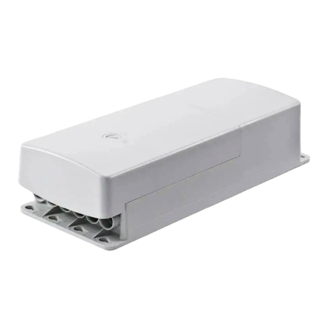
SKF BPSG2-PTA-MOD-EX-SS Manual

PR
E
AS
S
EX
-
(Original
2006/42/
E
E
S
S
S
E
M
-
SS
operatin
g
E
C)
S
UR
E
M
BL
Y
g
and mai
n
APTXM1
E
T
R
Y
B
P
n
tenance
AEN.docx 01.07.2
0
R
A
N
PS
G
instructi
o
13 Rev. 1A
N
S
M
G
2-
P
o
ns accor
d
ITT
E
P
TA
-
d
ing to E
U
E
R
-
M
O
U
Directiv
e
O
D-
e

TABLE O
1 EC Decl
a
2 General
D
3 Design...
4 Operatio
n
4.1 Start-u
p
5 Settings.
6 Technic
a
6.1 Techni
c
6.2 Conne
c
6.3 Symbol
s
7 Troubles
7.1 Trouble
8 Spare pa
9 Contact i
1 APP
E
F CONTE
N
a
ration of in
c
D
escription
.
...................
.
n
.................
.
p
..................
.
...................
.
a
l Specificat
c
al Data.......
.
c
tions...........
.
s
.................
.
hooting .....
.
shooting Ta
b
rts..............
.
nformation
.
E
NDIX
N
TS
c
orporatio
n
.
...................
.
...................
.
...................
.
...................
.
...................
ion..............
.
...................
.
...................
.
...................
.
...................
b
le...............
.
...................
.
...................
APTXM1
..................
.
...................
.
...................
.
...................
.
...................
.
...................
.
...................
.
...................
.
...................
.
...................
.
...................
.
...................
.
...................
.
...................
.
AEN.docx 01.07.2
0
.
...................
.
...................
.
...................
.
...................
....................
.
...................
.
...................
....................
....................
....................
.
...................
....................
.
...................
.
...................
13 Rev. 1A
...................
.
...................
.
...................
.
...................
.
...................
...................
.
...................
.
...................
...................
...................
...................
.
...................
...................
.
...................
.
.
...................
.
...................
.
...................
.
...................
.
...................
.
...................
.
...................
.
...................
.
...................
.
...................
.
...................
.
...................
.
...................
.
...................
.
...................
.
...................
.
...................
.
...................
...................
.
...................
.
...................
...................
...................
...................
.
...................
...................
.
...................
.
...................
.
..................
.
.
..................
.
.
..................
.
.
..................
.
....................
.
..................
.
.
..................
.
....................
....................
....................
.
..................
.
....................
.
..................
.
.
..................
.
.
..
.
1
.
1
.
1
1
.
2
.
2
2
3
3
.
4
4
.
5
.
5

APTXM1AEN.docx 01.07.2013 Rev. 1A
1 EC Declaration of incorporation
The original Declaration of Incorporation of Partly-Completed Machinery
(Machine Directive 2006/42/EC, Annex II, Part 1, Section B)
Oy SKF Ab
Teollisuustie 6 (P.O. Box 80)
FIN-40951 MUURAME
Person authorised to compile the relevant technical documentation:
Technical Manager and Product Manager, Centralized Lubrication Systems, Muurame Unit.
Herewith declares that for the partly completed machinery:
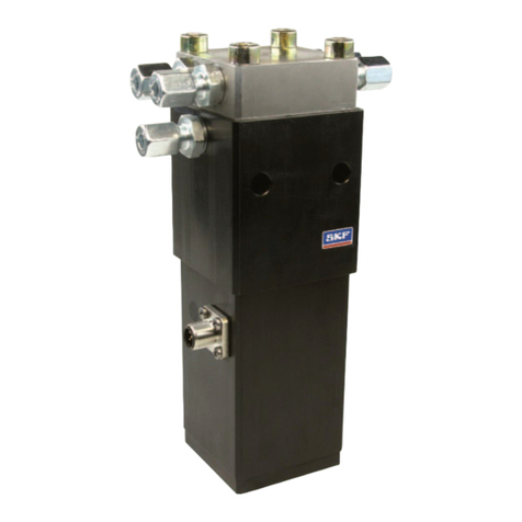
PRESSURE TRANSMITTER ASSEMBLY BPSG2-PTA-MOD-EX-SS
The following directives
94/9/CE (ATEX)
97/23/CE (DEP)
2004/108/CE (CEM
have been insured in the pressure transmitter supplier's insurance in the Appendix 1
This partly completed machinery must not be put into service until the final machinery into which it is to be
incorporated has been declared in conformity with the provisions of the Machinery Directive 2006/42/EC,
where appropriate.
Muurame 14.12.2012
Place Date
Tuomo Helminen
Local Manager

2 G
The pressu
r
tem.
3 D
Note!
Pressure tr
a
the main lin
4
O
The task of
sure trans
m
and the inf
o
control unit.
4.1
S
The pressu
r
Warnin
and also i
n
follow the
s
equipmen
t
ener
a
r
e transmitt
e
esig
n
a
nsmitter as
s
es.
O
pera
t
the pressur
e
m
itters, whic
h
o
rmation is t
r
.
S
tart-u
p
Warnin
voltage m
u
the syste
m
Warnin
fore remo
v
componen
the air cau
r
e transmitt
e
g Read
a
n
the SKF m
a
s
e instructio
n
t
that is lubri
c
a
l D
e
e
r assembly i
n
The numbe
s
embly (pos
.
t
ion
e
transmitter
h
are installe
d
r
ansmitted t
o
p
g Electri
c
u
st be shut o
m
or compon
e
g Make
s
v
ing the pres
ts are being
sing injury t
o
e
r assembly i
APTXM
1
a
nd follow th
a
nual "Safet
y
s could res
u
c
ated.
e
scri
p
s the contro
l
rs in bracke
t
.
5B) 2) con
s
assembly i
s
d
in the bod
y
o
the control
u
c
al connecti
o
ff before tou
c
e
nt
s
ure that the
s
ure transm
i
disconnect
e
o
people or
d
s installed o
1
AFI.doc
x
25.06.20
1
h
e safety pre
c
y
and gener
a
u
lt in serious
p
tion
l
unit of the
o
t
s are the po
s
ists of a fra
m
s
to measure
y
of the asse
unit. The pr
e
o
ns must on
l
ching electri
e
re is no pre
s
i
tter assemb
e
d or opene
d
d
amage to t
h
n the base
p
1
3 Rev. 1A
c
autions an
d
a
l instruction
injury or da
m
o
perating pr
e
sition numb
e
m
e and pres
s
the pressur
e
mbly, meas
u
e
ssure of the
l
y be made
b
c
ally condu
c
s
sure in the
s
ly. If the sys
t
, the compo
n
e environm
e
p
late of the d
o
d
general ins
t
s
for lubrica
t
m
age to the l
e
ssure in a c
e
e
rs for Figur
e
s
ure transmi
t
e
in the lubri
c
u
re pressure
main lines
c
b
y qualified
e
c
tive parts or
s
ystem. Det
a
t
em is under
n
ents or lub
r
e
nt.
o
ser group
u
s
tructions in
t
t
ion systems
ubrication s
y
entralized lu
e
1.
tters (pos. 1
cation syste
m
of the passi
c
an be moni
t
e
lectricians.
O
opening an
y
a
ch from the
r
pressure w
h
r
icant might
b
u
nder the do
s
1 (5)
t
his manual
.
"
Failure to
y
stem or the
brication sy
s
)
for both of
m
. The pres
-
ng lubricant
t
ored from th
O
perating
y
parts of
pipes be-
h
en the
b
e flung in
s
er.
s
-
-
e

5 S
e
See SKF
M
See SKF D
See SKF D
6 T
e
6.1 T
Table 1 T
e
Quantit
y
t
p
U
I
ATEX
e
ttin
g
M
AXILUBE /
U
UOFLEX /
S
UOFLEX /
S
e
chn
echni
c
e
chnical dat
a
Value
-40…+80
0–250
24 (10-30)
4–20
II 1/2 G EX
T
g
s
U
ser interfa
c
S
KF ST-134
0
S
KF ST-144
0
ical
S
c
al Dat
a
a
U
n
°C
ba
V
D
m
A
ia IIC
APTXM
1
e IF-105 / S
e
0
Control Ce
n
0
Control Ce
n
S
pec
i
a
n
it
D
o
r
p
D
C
s
A
o
1
AFI.doc
x
25.06.20
1
e
ttings
n
ter / Settin
g
n
ter / Settin
g
i
ficat
D
escription
o
peration te
m
p
ressure ra
n
s
upply volta
g
o
utgoing sig
n
1
3 Rev. 1A
g
s
g
s
ion
m
perature
n
ge
g
e
n
al: pressur
e
e
signal fro
m
m
the pressu
r
2 (5)
r
e transmitte
r
r

6.2
C
Lubricant c
o
inputs:
output
s
Electrical c
o
4 -cabl
e
inputs:
output
s
6.3
S
Table 2
BPSG2-P
T
BPSG:
2:
PTA:
MOD:
EX:
xx:
Example:
BPSG2-PT
A
Type
BPSG2-P
T
C
onne
c
o
nnections:
4 pcs
s
: 4 pcs
o
nnections:
e
, L -plug,
D
supply volta
s
: output sig
n
S
ymbol
Symbo
l
T
A-MOD-E
X
A
-MOD-EX-
S
TA
-MOD-E
X
c
tions
D
IN EN 175
3
ge
n
al
s
l
s
X
-xx
S
S
2-linjainen
painelähe
t
voitelujärj
e
modulirak
e
painelähe
t
rungon m
a
X
-SS
APTXM
1
01-803 IP6
5
Abbreviati
o
BPSG:
2
PTA
MOD
EX
ZN
SS
paineläheti
n
t
inasennelm
a
e
stelmätyyp
p
e
nne
t
timen tyyppi
a
teriaali, ruo
s
Code
12385328
1
AFI.doc
x
25.06.20
1
5
o
n Des
c
Bas
e
2-lin
Pre
s
mod
pres
bod
y
zinc
-
bod
y
acid
n
asennelma
a
, Pressure
T
p
i, SKF Duo
F
s
tumaton ter
ä
Draw
i
1
3 Rev. 1A
c
ription
e
Plate SKF
e
pressure t
r
s
sure Trans
m
ule structur
e
sure transm
i
y
material,
-
coated and
y
material,
resistant st
e
T
ransmitter
A
F
lex
ä
s
i
ng numbe
r
DuoFle
x
r
ansmitter a
s
m
itter Assem
b
e
i
tter type
y
ellow-passi
e
el AISI 316
A
ssembly
s
sembly
bly
i
vated steel
3 (5)

7 T
r
7.1 T
Table 3
Operation
The contro
shows ---
The contro
shows 250
The data f
r
transmitter
lubrication
r
oub
l
roubl
e
Troubl
e
disturbanc
e
l center disp
l center disp
constantly
r
om the pres
s
arrive at se
p
lines
l
esh
o
e
shoot
i
e
shooting Ta
e
Ca
u
di
s
lay
lay
s
ure
p
arate
Pr
e
co
n
Th
e
ble
Th
e
cir
c
Th
e
pu
t
APTXM
1
o
otin
g
i
ng Ta
b
ble
u
se of oper
a
s
turbance
e
ssure trans
m
n
nected
e
pressure t
r
s
are cut
e
cables ha
v
c
uited
e
pressure t
r
s are conne
c
1
AFI.doc
x
25.06.20
1
g
b
le
a
tion
m
itters are n
o
r
ansmitter's
c
v
e short-
r
ansmitter's i
c
ted wrongl
y
1
3 Rev. 1A
Solut
i
o
t
c
a-
n-
y
Conn
e
in acc
electr
o
Chec
k
Chec
k
Chec
k
i
on
e
ct the pres
s
o
rdance wit
h
o
nical drawi
n
k
the cables.
k
the cables
k
the connec
t
s
ure transmi
t
h
the separa
t
n
g.
c
tions.
4 (5)
t
ters
t
e

8 S
See BPSG
2
Figure 1.
Table 4 S
p
Item
1
2
3
9 C
Oy SKF Ab
P.O. Box 8
0
FI-40951 M
FINLAND
Tel. +358 (
0
Fax. +358
www.skf.co
pare
2
-PTA-MOD
-
p
are parts
Descriptio
Pressure tr
a
Pressure tr
a
O-circuit 6.
3
onta
c
0
(Teollisuu
s
UURAME
0
) 207 400 8
(0) 207 400
m
part
s
-
EX-SS -
p
r
e
n
a
nsmitter
a
nsmitter as
3
x 2.4
c
t in
f
s
tie 6)
00
899
APTXM
1
s
e
ssure trans
m
sembly
f
orm
a
1
AFI.doc
x
25.06.20
1
m
itter asse
m
a
tion
1
3 Rev. 1A
m
bly spare p
a
a
rts (drawing
Order co
d
1260523
8
1238532
8
1268040
0
g
1 and table
de
8
8
0
5 (5)
4 / 361880)
.
.


This manual suits for next models
1
Table of contents
Other SKF Control Unit manuals

SKF
SKF Lincoln 85307 User manual

SKF
SKF LC502 User manual

SKF
SKF Lincoln 85307 User manual

SKF
SKF Lincoln 85307 User manual

SKF
SKF MAXILUBE MAX 230-IF105 Series User manual

SKF
SKF CMPT DCL User manual

SKF
SKF SMBM-X Series User manual

SKF
SKF LCG2-A Series User manual

SKF
SKF LINCOLN 85831 User manual

SKF
SKF SGA-011 User manual