SLAT SYNAPS IP SPACE BOX Series User manual

Code :
- NDI :
SYNAPS IP SPACE BOX
Micro-UPS
Français - Notice d’installation
Vous trouverez dans cette notice toutes les indications à suivre pour
l’installation de l’alimentation sans interruption SYNAPS IP de
marque SLAT. Pour le bon fonctionnement du produit, nous vous
conseillons de les suivre très attentivement.
Consignes de sécurité
SYNAPS IP est un Micro-UPS DC destiné à être raccordé au réseau
115 V / 230 V de distribution publique. Il assure la continuité de ser-
vice des équipements en cas de coupure de courant. La fonction
secours est intégrée au produit. Vous trouverez de plus amples
informations dans le manuel d’utilisation à télécharger sur le site
www.slat.com.
•Un dispositif de sectionnement doit être prévu en amont confor-
mément aux règles en vigueur.
•Afin d’éviter tout risque de choc électrique, toute INTERVEN-
TION doit être réalisée HORS TENSION.
•L’intervention doit être réalisée uniquement par du personnel
habilité.
•SYNAPS IP est conçu pour être installé en extérieur verticale-
ment sur un mur ou dans une chambre de tirage.
Le refroidissement par convection naturelle du produit nécessite
un dégagement minimum de 50 mm de chaque côté.
•Respecter les limites thermiques et mécaniques.
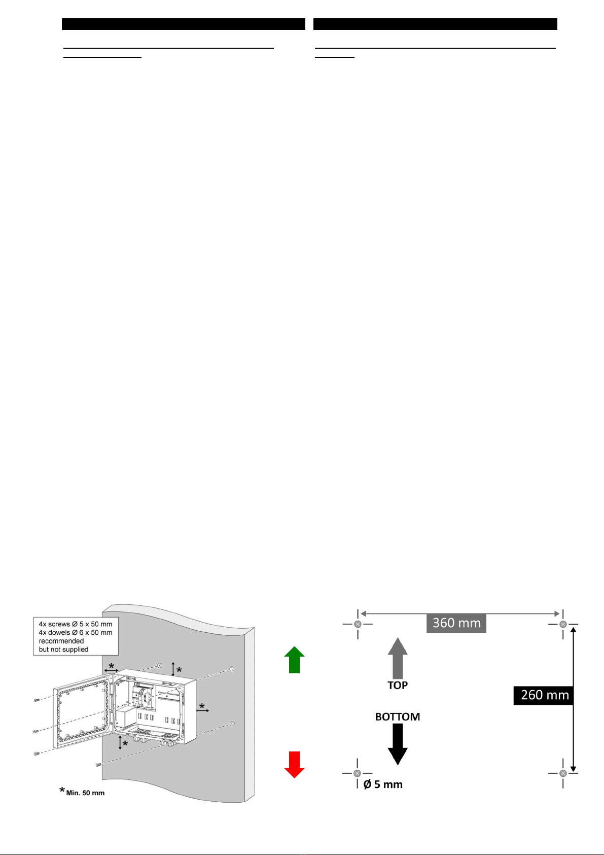
Montage au mur ou dans une chambre de tirage
(figure 1 et 2):
•Placer le produit sur un support en béton par exemple et repérer
les points de fixations ou utiliser les dimensions indiquées dans
cette notice (passage des 4 vis).
•Percer le support et mettre 4 chevilles (non fournies – ø 6 x
50 mm recommandées) appropriées au support.
•Fixer le produit à l’aide de 4 vis (non fournies – ø 5 x 50 mm
recommandées).
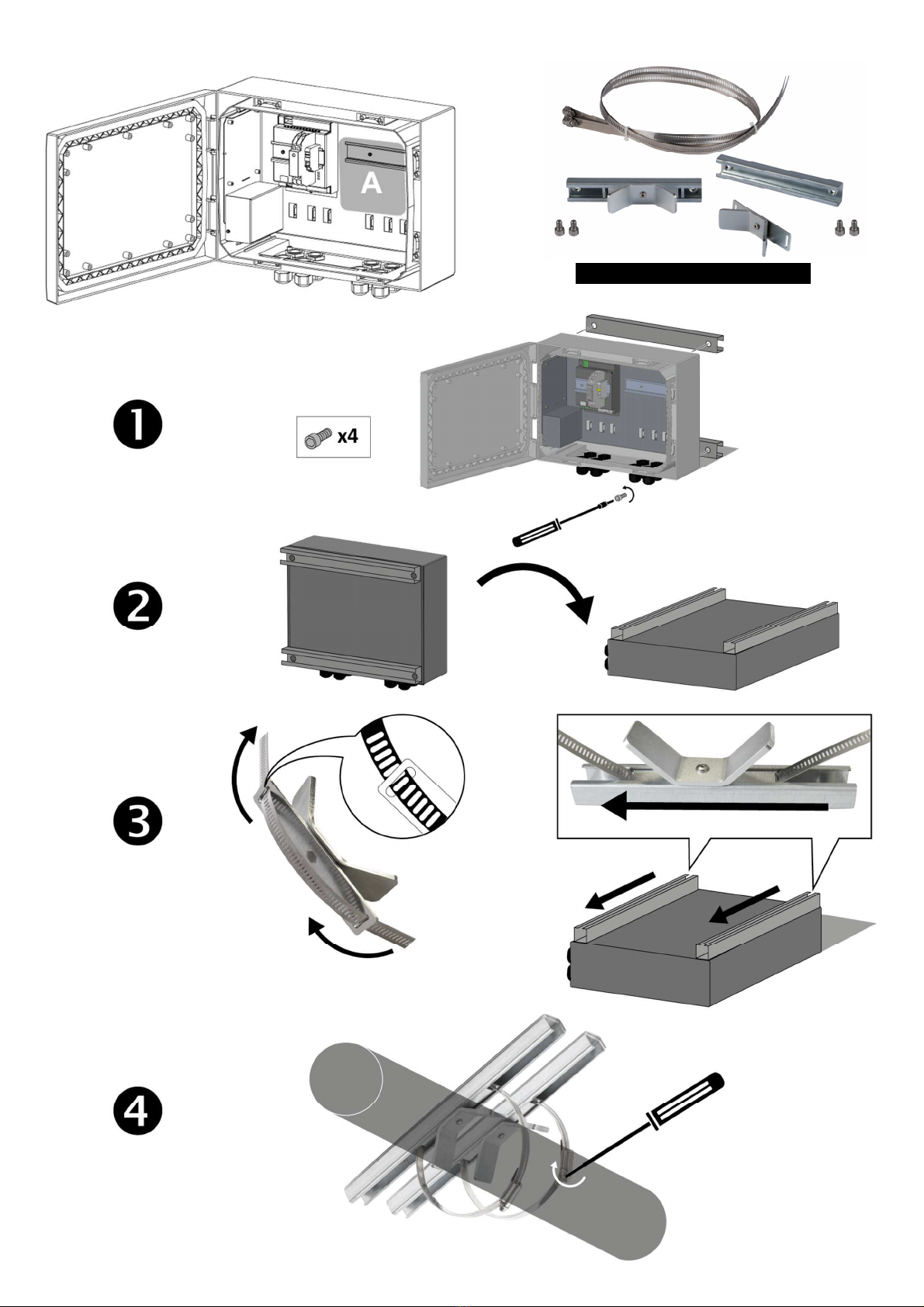
Montage sur mât/poteau (figure 4) :
Il appartient à l’installateur de s’assurer de la capacité d’accueil de
la charge du mât/poteau.
Avec l’option kit de montage sur mât/poteau
•Monter le kit sur le produit à l’aide d’un tournevis porte- embout
[douille ¼ et embout 6 pans ¼ (H6)].
•Fixer le produit sur le mât à l’aide de la bride de serrage (ø min.
100 – max. 300 mm).
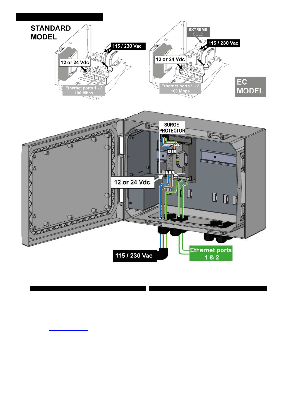
Raccordement (figure 5, 6 et 7) :
•Dimensionner et protéger les câbles en fonction du courant
d’entrée/sortie maximum.
•Les câbles d’entrée secteur doivent être raccordés au bornier du
parafoudre (voir figure 4).
•Raccorder le fil de terre en 1er et lors d’un démontage le
déconnecter en dernier.
•Respecter les couleurs des câbles :
•Fil de terre jaune/vert
•Fil neutre bleu (N)
•Fil phase marron (L)
•Raccorder SYNAPS IP aux applications via le bornier à vis utili-
sation 12 Vdc ou 24 Vdc en respectant les polarités. Les 2 ports
de communication IP ont une vitesse de 10 /100 Mbps. Chaque
port est numéroté sur le produit. Les 2 ports peuvent être utilisés
indifféremment.
•La languette de la prise RJ45 est à positionner sur l’avant.
Stockage prolongé :
•Stockage prolongé ou déconnexion, appuyer sur le bouton
arrêt fonction secours (voir étiquette à l’intérieur de la porte).
English - Installation manual
In this manual you will find all the instructions you need to install the
uninterruptible power supply by SLAT SYNAPS IP. For a proper
functioning, we advise you to follow them carefully.
Safety precautions
SYNAPS IP is a DC Micro-UPS to be connected to the 115 V / 230 V
mains supply. It ensures the continuity of service for the equipment
in case of power failure. The backup function is integrated into the
product. You can find more information in the using manual, which
is ready for download on the site www.slat.com.
•A disconnect-switch or circuit-breaker shall be installed
upstream according to standards.
•To avoid any risk of electric shock, all INTERVENTION must be
carried out with the equipment being SWITCHED OFF.
•The operation must only be performed by qualified personnel.
•SYNAPS IP is designed to be installed vertically on a wall, or
pull-out room. Cooling by natural convection of the product
requires a minimum clearance of 50 mm on each side.
•Observe the thermal and mechanical limits.
Wall mounting or pull-out room mounting (figure 1 and 2):
•Place the product on a concrete substrate for example and
resecure the fastening points or use the dimensions specified in
this manual (passing of the 4 screws).
•Drill the substrate and place 4 appropriate dowels for the sub-
strate (not supplied – ø 6 x 50 mm recommended).
•Secure the product with 4 screws (not supplied – ø 5 x 50 mm
recommended).
Mounting on a post (figure 4):
It is the responsibility of the installer to ensure the capacity of the
post load.
With option post mounting kit
•Mount the kit on the product using a bit screwdriver [¼ socket
and ¼ (H6) screwdriver bit].
•Secure the product to the post using the clamp. (ø min. 100 –
max. 300 mm)
Connection (figure 5, 6 and 7):
•Size and protect cables according to the maximum current input/
output.
•The mains input cables must be connected to the surge protector
terminal (see figure 4).
•Connect the ground wire first and disconnect it last.
•Respect the colors of the cables:
•Yellow / green wire for ground
•Blue wire for neutral (N)
•Brown wire for phase (L)
•Connect SYNAPS IP to the applications via the screw terminal
block 12 Vdc or 24 Vdc respecting the polarities.2 Ethernet ports
communication speed is 10/100 Mbps. Each port is numbered
on the product. Both ports can be used indifferently.
•The tab on the RJ45 jack must be positioned on the front.
Prolonged storage :
•For prolonged storage or disconnection, press the button stop
backup function (for the location of “Disconnect backup push-
button” see label on the inside of the door).
Désignation
Codification
SYNAPS
12V
3E
IP
SPACE BOX
89231734
SYNAPS 12V 3E IP SPACE BOX
EC
89231744
SYNAPS
24
V 3E IP SPACE BOX
89431734
SYNAPS
24
V 3E IP SPACE BOX
EC
89431744
2
Top
Bottom
Français - Notice d’installation
Normes et directives, protection de l’environnement et
de la santé publique
EN 60950 -1 (2006) +A11 (2009) + A1 (2010) + A12 (2011) + A2
(2013) classe TBTS ; EN 62368-1 (2014) ;
EN 61000-6-1 (2007) ; EN 61000-6-2 (2005) ;
EN 61000-6-3 (2007) ; EN 61000-6-4 (2007) + A1 (2011) ;
55032 (2015) classe B
UN 38.3 (recommandations relatives au transport des
marchandises dangereuses)
SLAT assure le recyclage de ses produits en fin de vie.
Caractéristiques mécaniques
•Boîtier en polycarbonate
•Indice de protection : IP65 (fixé au mur ou dans une
chambre de tirage) – IK 10
•Dimensions : L 400 x H 300 x P 152,5 mm
•Espace client disponible (figure 3) :
A : L 200 x H 150 x P 120 mm
•Poids : 5.1 kg
Spécifications électriques de sortie
•12 Vdc ou 24 Vdc 55W.
Spécifications électriques d’entrée
•Tension réseau : 115/230 Vac (97,8-264,5 Vac)
•Fréquence : 50-60 Hz (45-65 Hz)
•Classe I
•Régimes de neutre : TT, TN, IT
•Courant primaire @ 115 V : 0,9 A
•Courant primaire @ 230 V : 0,48 A
•Courant primaire @ 97,8 V : 1,1 A
•Courant primaire @ 264,5 V : 0,41 A
•Disjoncteur à prévoir en amont : courbe C ou D (calibre 2 A)
Spécifications environnementales
•Température de fonctionnement :
-5°C … +50°C
•-20°C … +50°C version EC
•Température de stockage :
-25°C … +60°C
•Humidité relative en fonctionnement :
0% … 100% (condensant)
Smart Backup
•Batterie Lithium-ion intégrée
•Technologie : LiFePO4
•Pas de risque d’emballement thermique
•Stockage 9 mois sans recharge
•Durée de vie : 10 ans @ 25°C
Communication
•2 ports Ethernet 10/100 Mbps
•Protocoles de communication :
HTTPS, IPv4, ICMP, DHCP, SNMP
•Sans serveur DHCP :
Adresse IP 192.168.1.1
Masque réseau 255.255.255.0
Pas de gateway
Raccordements
•Section des câbles : 0.3…2.5 mm², longueur à dénuder : 7
mm
•Le raccordement s’effectue à travers des passe-fils.
•Cordon Ethernet Cat 5e ou plus / blindé ou non blindé /
câbles droits ou croisés
English - Installation manual
Standards and directives, environment and public health
protection
EN 60950 -1 (2006) +A11 (2009) + A1 (2010) + A12 (2011) + A2
(2013) SELV class ; EN 62368-1 (2014) ;
EN 61000-6-1 (2007) ; EN 61000-6-2 (2005) ; EN 61000-6-
3 (2007) ;
EN 61000-6-4 (2007) + A1 (2011) ;
55032 (2015) class B
UN38.3 (Recommendations on the Transport of Dangerous Goods)
SLAT recycles its products at the end of life.
Mechanical characteristics
•Polycarbonate housing
•Protection class: IP65 (wall mounted or pull-out room
mounted) – IK10
•Dimensions: W 400 x H 300 x D 152.5 mm
•Available customer space (figure 3):
A : W 200 x H 150 x P 120 mm
•Weight: 5.1 kg
Electrical output specifications
•12 Vdc or 24 Vdc 55W
Electrical input specifications
•Mains voltage: 115/230 Vac (97.8-264.5 Vac)
•Frequency: 50-60 Hz (45- 65 Hz)
•Class I
•Neutral systems: TT, TN, IT
•Primary current @ 115 V: 0.9 A
•Primary current @ 230 V: 0.48 A
•Primary current @ 97.8 V: 1.1 A
•Primary current @ 264.5 V: 0.41 A
•Provide an upstream circuit breaker: type C or D (rating: 2 A)
Environmental specifications
•Operating temperature:
-5°C … +50°C
•-20°C … +50°C EC model
•Storage temperature:
-25°C … +60°C
•Operating relative humidity:
0% … 100% (condensing)
Smart Backup
•Li-ion battery integrated
•Technology: LiFePO
4
•No risk of thermal runaway
•Storage: 9 months without recharging
•Life span: 10 years @ 25°C
Communication
•2 Ethernet ports: 10/100 Mbps
•Communication protocols:
HTTPS, IPv4, ICMP, DHCP, SNMP
•Without DHCP server:
IP address 192.168.1.1
Netmask 255.255.255.0
No gateway
Connections
•Cable section: 0.3 … 2,5 mm², length to be stripped: 7 mm
•The cabling is performed via rubber-gommets
•Cat 5e or higher Ethernet cable / shielded or unshielded /
straight or crossed cables
Figure 1 – Wall mounting or pull-out room mounting Figure 2 – Dimensions and pitches
3
Figure 3 – Customer space
Option post mounting Kit:
Figure 4 – Post mounting
4
Mise en service et Assistance technique
Certificat racine et manuel d’utilisation à télécharger sur
www.slat.com sur l’espace documents clients. Le certificat ra-
cine est indispensable pour l’utilisation du produit en HTTPS
et pour communiquer en toute sécurité avec lui.
Aucun retour de matériel ne sera accepté sans délivrance pré-
alable d’un numéro de RMA. Pour une demande de RMA
contactez serv[email protected].
Pour une assistance technique complémentaire contactez la
hotline SLAT: +33 4 78 66 63 70
Commissionning and Technical Assistance
The root certificate and the operating instructions can be
downloaded from www.slat.com in the library account. The
root certificate is essential for using the product in HTTPS and
for communicating with it safely.
No equipment return will be accepted without prior issuance
of a RMA- Number. For a RMA request contact
.
For additional technical assistance, contact the SLAT hotline:
+33 4 78 66 63 70
SLAT – 11 rue Jean Elysée Dupuy – BP66
69543 Champagne au Mont d’Or – France
Tel : +33 478 66 63 60 – Fax : +33 478 47 54 33
E-Mail : comm@slat.fr – www.slat.com
SLAT GmbH – Leitzstraße 45 - 70469 Stuttgart – Deutschland
Tel.: +49 711 899 890 08 - Fax: +49 711 899 890 90
E-mail: info@slat-gmbh.de – www.slat.com
Connections IP model- Fig. 5,6 & 7
Fig 5 Fig 6
Fig 7
This manual suits for next models
4
Other SLAT Power Supply manuals

SLAT
SLAT AESI C24 User manual

SLAT
SLAT AES Series User manual

SLAT
SLAT AES Series User manual

SLAT
SLAT AES User manual

SLAT
SLAT AES 28V/8A User manual

SLAT
SLAT Classic Series User manual

SLAT
SLAT AESI C24 User manual

SLAT
SLAT Classic Series User manual

SLAT
SLAT SON 24V 12A MS150 RACK User manual

SLAT
SLAT AXS3 Instruction sheet


Popular Power Supply manuals by other brands


Bosch
Bosch PSB 0004 A Quick installation guide

Delton
Delton 301D operation instruction

National Instruments
National Instruments NI PXIe-4113 CALIBRATION PROCEDURE

BRONKHORST
BRONKHORST MASS-VIEW series instruction manual

Elektro-Automatik
Elektro-Automatik PS 8000 DT instructions

Gallagher
Gallagher MB1800i instructions