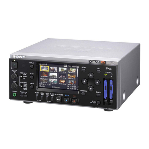
Sony PMW50 User manual

PORTABLE MEMORY RECORDER
PMW-50
SERVICE MANUAL
1st Edition

警告
このマニュアルは, サービス専用です。
お客様が, このマニュアルに記載された設置や保守, 点検, 修理などを行うと感電や火災,
人身事故につながることがあります。
危険をさけるため, サービストレーニングを受けた技術者のみご使用ください。
WARNING
This manual is intended for qualified service personnel only.
To reduce the risk of electric shock, fire or injury, do not perform any servicing other than that
contained in the operating instructions unless you are qualified to do so. Refer all servicing to
qualified service personnel.
WARNUNG
Die Anleitung ist nur für qualifiziertes Fachpersonal bestimmt.
Alle Wartungsarbeiten dürfen nur von qualifiziertem Fachpersonal ausgeführt werden. Um die
Gefahr eines elektrischen Schlages, Feuergefahr und Verletzungen zu vermeiden, sind bei
Wartungsarbeiten strikt die Angaben in der Anleitung zu befolgen. Andere als die angegeben
Wartungsarbeiten dürfen nur von Personen ausgeführt werden, die eine spezielle Befähigung
dazu besitzen.
AVERTISSEMENT
Ce manual est destiné uniquement aux personnes compétentes en charge de l’entretien. Afin
de réduire les risques de décharge électrique, d’incendie ou de blessure n’effectuer que les
réparations indiquées dans le mode d’emploi à moins d’être qualifié pour en effectuer d’autres.
Pour toute réparation faire appel à une personne compétente uniquement.
PMW-50

CAUTION
Danger of explosion if battery is incorrectly replaced.
Replace only with the same or equivalent type rec-
ommended by the manufacturer.
When you dispose of the battery, you must obey the
law in the relative area or country.
ATTENTION
Il y a danger d’explosion s’il y a remplacement incor-
rect de la batterie. Remplacer uniquement avec
une batterie du même type ou d’un type équivalent
recommandé par le constructeur.
Lorsque vous mettez la batterie au rebut, vous devez
respecter la législation en vigueur dans le pays ou la
région où vous vous trouvez.
VORSICHT
Explosionsgefahr bei Verwendung falscher Batterien.
Batterien nur durch den vom Hersteller empfohlenen
oder einen gleichwertigen Typ ersetzen.
Wenn Sie die Batterie entsorgen, müssen Sie die
Gesetze der jeweiligen Region und des jeweiligen
Landes befolgen.
注意
指定以外の電池に交換すると,破裂する危険があります。
必ず指定の電池に交換してください。
使用済みの電池は,国または地域の法令に従って
処理してください。
FÖRSIKTIGHET!
Fara för explosion vid felaktigt placerat batteri.
Byt endast mot samma eller likvärdig typ av batteri,
enligt tillverkarens rekommendationer.
När du kasserar batteriet ska du följa rådande lagar
för regionen eller landet.
PAS PÅ
Fare for eksplosion, hvis batteriet ikke udskiftes
korrekt.
Udskift kun med et batteri af samme eller tilsvarende
type, som er anbefalet af fabrikanten.
Når du bortskaffer batteriet, skal du følge
lovgivningen i det pågældende område eller land.
HUOMIO
Räjähdysvaara, jos akku vaihdetaan virheellisesti.
Vaihda vain samanlaiseen tai vastaavantyyppiseen,
valmistajan suosittelemaan akkuun.
Noudata akun hävittämisessä oman maasi tai
alueesi lakeja.
FORSIKTIG
Eksplosjonsfare hvis feil type batteri settes i.
Bytt ut kun med samme type eller tilsvarende
anbefalt av produsenten.
Kasser batteriet i henhold til gjeldende avfallsregler.
⊼ᛣ
⊼ᛣ
བᵰᤶⱘ⬉∴ϡℷ⹂ˈህӮ᳝⟚⚌ⱘ䰽DŽ
াᤶৠϔ㉏ൟࠊ䗴ଚ㤤ⱘ⬉∴ൟোDŽ
໘⧚⬉∴ᯊˈᖙ乏䙉ᅜⳌ݇ഄᆊⱘ⊩ᕟDŽ
PMW-50


Table of Contents
Manual Structure
Purpose of this manual....................................................................................................................3
Related manual............................................................................................................................3
1. Service Overview
1-1. External Connectors...........................................................................................................1-1
1-1-1. Connector Input/Output Signals........................................................................................1-1
1-2. Location of Printed Wiring Boards............................................................................................1-3
1-3. Circuit Description............................................................................................................1-4
1-3-1. Video Signal System...................................................................................................1-4
1-3-2. Media Recording/Playback System....................................................................................1-4
1-3-3. Audio System...........................................................................................................1-5
1-3-4. System Control.........................................................................................................1-6
1-3-5. Power Supply System..................................................................................................1-7
1-4. Service Tools/Measuring Equipment List.....................................................................................1-9
1-4-1. Service Tools...........................................................................................................1-9
1-4-2. Measuring Equipment..................................................................................................1-9
1-5. Firmware Upgrade...........................................................................................................1-10
1-6. Electrical Alignment.........................................................................................................1-11
1-7. Circuit Protection Parts......................................................................................................1-12
1-7-1. Circuit Protection Element............................................................................................1-12
1-7-2. Replacing Fuses and IC Links.........................................................................................1-12
1-8. Notes on Service.............................................................................................................1-13
1-8-1. Actions to Be Taken when Replacing Parts and Boards..............................................................1-13
1-8-2. Preparation for Replacing Parts and Boards..........................................................................1-13
1-8-3. Notes on Replacing Onboard Parts....................................................................................1-13
1-8-4. Backup Battery........................................................................................................1-13
1-9. Flexible Card Wire and Fine-Wire Coaxial Cable...........................................................................1-14
1-9-1. Disconnecting/Connecting Flexible Card Wire.......................................................................1-14
1-9-2. Disconnecting/Connecting Fine-Wire Coaxial Cable.................................................................1-14
1-10. Lead-free Solder.............................................................................................................1-17
2. Replacement of Main Parts
2-1. Outline of Replacement Procedure............................................................................................2-1
2-2. LCD Assembly................................................................................................................2-2
2-3. Top/Bottom Panel Assembly..................................................................................................2-5
2-4. Front Panel Assembly/SxS Lid................................................................................................2-7
2-5. Option Cover/HP Jack Cover.................................................................................................2-9
2-6. Rear Panel Assembly........................................................................................................2-10
2-7. Bottom Frame................................................................................................................2-11
2-8. Front Frame Assembly.......................................................................................................2-13
2-9. IO-256 Board................................................................................................................2-16
2-10. SWC-55 Board/EC-115 Board...............................................................................................2-18
2-11. KSW-63/KSW-64/HN-407 Board...........................................................................................2-22
2-12. DCP Board...................................................................................................................2-24
2-13. DPR Board...................................................................................................................2-26
PMW-50 1
2-14. AU Board....................................................................................................................2-28
2-15. RE-298/RE-299/RE-300 Board..............................................................................................2-30
2-16. Battery Case D SUB Assembly/DC Board..................................................................................2-31
2-17. IF-1188 Board/LCD Panel...................................................................................................2-33
2-18. Lithium Battery..............................................................................................................2-38
3. SERVICE Menu
3-1. Outline of SERVICE Menu...................................................................................................3-1
3-1-1. Basic Menu Operations.................................................................................................3-1
3-1-2. SERVICE Menu Structure..............................................................................................3-1
3-1-3. Display/Hide the SERVICE Menu.....................................................................................3-1
3-2. SERVICE Menu List..........................................................................................................3-3
3-2-1. INFORMATION Menu................................................................................................3-3
3-3. Self-Diagnosis.................................................................................................................3-4
3-3-1. Self-Diagnostic Items...................................................................................................3-4
3-3-2. Executing Self-Diagnosis...............................................................................................3-4
3-3-3. Details of Self-Diagnosis...............................................................................................3-5
3-4. Error Code List...............................................................................................................3-11
4. Spare Parts
4-1. Note on Repair Parts..........................................................................................................4-1
4-2. Exploded Views...............................................................................................................4-2
4-3. Electrical Parts List..........................................................................................................4-15
4-4. Supplied Accessories........................................................................................................4-17
5. Block Diagrams
Overall..................................................................................................................................5-1
6. Schematic Diagrams
Frame Wiring...........................................................................................................................6-1
PMW-50 2

Manual Structure
Purpose of this manual
This document is the service manual of Portable Memory Recorder PMW-50.
When servicing this unit, parts are replaced on a board basis in principle. Therefore, this manual includes no circuit
diagram or board layout.
Related manual
The following manual is provided for this unit in addition to this “Service Manual”.
If you need the manual, contact your local Sony Sales Office/Service Center.
• Operating Instructions (Included on the CD-ROM)
This manual contains information required to operate and maintain this unit.
• Before Using this Unit (Supplied with this unit)
This manual contains the important reminder and specification of this unit.
PMW-50 3


Section 1
Service Overview
1-1. External Connectors
1-1-1. Connector Input/Output Signals
6
1
4
3
7912
10
5
28 11
Input/Output Signals
1. VIDEO OUT
BNC type, 1.0 Vp-p, 75 Ω, Unbalanced
2. HEADPHONE
Stereo mini jack
‒20.5 dBu (reference level output 16 Ω loaded)
Sound monitor, monaural/stereo selectable
3. SDI IN
SDI signal SMPTE 292M/259M compliant
BNC type, 0.8 Vp-p, 75 Ω, 270 Mbps/1.5 Gbps
4. SDI OUT
SDI signal SMPTE 292M/259M compliant
BNC type, 0.8 Vp-p, 75 Ω, 270 Mbps/1.5 Gbps
5. DC IN
- External View -
DC jack, Type 4
GNDEXT DC
6. AUDIO OUT L/R
(0 dBu = 0.775 Vrms)
RCA jack, Female
- External View -
12
No. Signal I/O Specifications
1 LINE (X) OUT Unbalanced, –10 dBu
2 LINE (G) — GND
7. i.LINK (HDV/DV)
14
- External View -
4-pin, IEEE1394, S400
No. Signal I/O Specifications
1 TPB– IN/OUT Strobe on receive, data on
transmit B (–)
2 TPB+ IN/OUT Strobe on receive, data on
transmit B (+)
3 TPA– IN/OUT Data on receive, strobe on
transmit A (–)
4 TPA+ IN/OUT Data on receive, strobe on
transmit A (+)
PMW-50 1-1

8. USB (OPTION)
USB (Type A), 4-pin
Signal standard: USB standard Ver. 2.0
- External View -
14
No. Signal I/O Specifications
1 USB VBUS — USB Vcc
2 DATA (–) IN/OUT I/O USB–
3 DATA (+) IN/OUT I/O USB+
4 GND — Ground
9. USB (DEVICE)
USB (Type B), 4-pin
Signal standard : USB standard Ver. 2.0
- External View -
1
4
2
3
No. Signal I/O Specifications
1 USB DEV
VBUS
— USB Vcc
2 DATA (–) IN/OUT I/O USB–
3 DATA (+) IN/OUT I/O USB+
4 GND — Ground
10. USB (SERVICE)
15
- External View -
5-pin, mini-B, USB2.0 Hi-Speed
No. Signal I/O Specifications
1 VCC — USB Vcc
2 D– IN/OUT I/O USB–
3 D+ IN/OUT I/O USB+
4 ID — NC
5 GND — Ground
11. BATTERY
- External View -
5-pin, Male
12 3 45
No. Signal I/O Specifications
1 BATT (+) — +11 to +17 V dc
2 BAT SCL OUT —
3 BAT SDA IN/OUT —
4 BATT ID
DATA
IN —
5 BATT (–) — —
12. HDMI OUT
- External View -
19-pin, Type A
19 1
18 2
No. Signal I/O Specifications
1 TMDS DATA2+ OUT —
2 TMDS DATA2
SHIELD
— —
3 TMDS DATA2– OUT —
4 TMDS DATA1+ OUT —
5 TMDS DATA1
SHIELD
— —
6 TMDS DATA1– OUT —
7 TMDS DATA0+ OUT —
8 TMDS DATA0
SHIELD
— —
9 TMDS DATA0– OUT —
10 TMDS CLOCK+ OUT —
11 TMDS CLOCK
SHIELD
— —
12 TMDS CLOCK– OUT —
13 CEC (N.C.) — —
14 RESERVED (N.C.) — —
15 SCL OUT —
16 SDA IN/OUT —
17 DDC/CEC GND — —
18 +5V POWER OUT —
19 HPD IN —
PMW-50 1-2

1-2. Location of Printed Wiring Boards
IF-1188
KSW-63
EC-115
SWC-55
DC-168
PSW-100
KSW-64
DCP-60
IO-257
HN-408
DPR-350
AU-349
RM-239
RE-300
RE-298
RE-299
IO-256
HN-407
PMW-50 1-3

1-3. Circuit Description
1-3-1. Video Signal System
DCP-60 Board
The HD/SD SDI input signal is input to IC100 on the DCP-60 board, in which cable correction and serial/parallel
conversion are performed. Converted parallel signals are sent to the input processing FPGA (IC200). Furthermore,
embedded audio signals (4ch) are separated by IC100 and are then sent to IC200.
IC200 performs the following processing and processed signals are sent to the router IC ANDV (IC1700).
• Detecting input synchronization (FVH) and extracting ANC data (except for audio data)
• Generating test signals (such as color bar)
• Converting the number of pixels (1920/1080 to 1440/1080)
• Audio signal interface
IC1700 has a function of interface with the media block and the baseband video processing IC T-ONE (IC900), and
outputs the following signals.
• HD/SD SDI output signals
Parallel HD/SD SDI output signals are converted to a serial signal by IC2201, and the serial signal is sent to the
SDI OUT connector.
• HDMI output signals
HDMI output signals are sent to the HDMI connector through IC1500.
• Analog video output signals
Digital video output signals are converted to analog video output signals by IC1600, and the analog video output
signals are sent to the VIDEO OUT connector on the IO-257 board.
IC900 outputs LCD video signals through the KSW-63 board to the 3.5-inch LCD. IC900 also has the following
functions.
• Video scaler (HD/SD output) processing
• Input synchronization processing
1-3-2. Media Recording/Playback System
DPR-350 Board
Output signals from the baseband processor IC (IC900) on the DCP-60 board are transferred to the router IC ANDV
(IC1700) on the DCP-60 board and the selector IC CAVS (IC100) on the DPR-350 board, and are then input to the
MPEG encoder/decoder TRINO (IC500, IC700) or the media block controller (IC1000).
The MPEG encoder/decoder (IC500, IC700) is a single-chip MPEG CODEC IC that encodes and decodes high-quality
HD image and audio signals in real time. It has various interfaces with MPEG video signal and video input/output,
MPEG audio signal and audio input/output, bitstream input/output, and the USB host.
The media block controller (IC1000) processes these signals and then files them, and writes/reads the file data to/from
the SxS memory card through the SWC-55 board or the EC-115 board with the PCI Express interface.
This controller performs operation opposite to this procedure in the playback mode.
Furthermore, the media block controller (IC1000) has an internal CPU and a USB device controller for router IC CAVS
(IC100) control, serial communication with the system controller (IC2101), and data communication with each controller
through the PCI bus.
A flash ROM (IC1101) is also connected to IC1000, and the CPU program in IC1000 is read at the first startup.
Controlled by the system controller (IC2101) in the same way as other main devices, the DPR-350 board performs video/
audio stream control, SxS memory card access, mass storage operation through the USB connection, and HDV device
control through the i-LINK connection.
PMW-50 1-4

Peripheral Devices
SxS memory card slot
The 2-channel PCI-Express signal from the media block controller (IC1000) is input to the two memory card slot boards
(SWC-55, EC-115) through the 0.4 mm-pitch 30-pin fine-wire coaxial cables connected to CN1400 and CN1401.
The 2-channel USB host signal that is output from the media block controller (IC1000) by controlling USB host controller
(IC1301) is sent to the SWC-55 and EC-115 boards through fine-wire coaxial cables in the same way as the PCI-Express
signal. IC1301 is controlled by IC1000 through the PCI bus.
USB device controller
USB device signals output from the USB device controller in the media block controller (IC1000) are input to the USB
TYPE-B connector (CN1100).
USB host controller
The USB host controller (IC1301) takes charge of one channel for connection to Wi-Fi adapter or USB memory in
addition to two channel of slots for SxS memory card.
The USB host signal input/output from the USB host controller (IC1301) is transferred from CN2501 through the
shielded harness to the IO-256 board, and is then transferred to the USB TYPE-A connector (CN101).
IC1301 is controlled by IC1000 through the PCI bus.
i-LINK controller
The i-LINK signal that is output from the i-LINK controller (IC1300) by controlling IC1300 from the media block
controller (IC1000) is sent to the 4-pin i-LINK connector (CN1300). IC1300 is controlled by IC1000 through the PCI
bus.
1-3-3. Audio System
AU-349 Board
The AU-349 board mainly has motherboard, audio, and RTC functions.
Motherboard function
The AU-349 board relays signals to main boards (DPR-350, DCP-60) and power supply boards (RE-299, RE-300) as
a motherboard function.
Audio signal flow
• Input
Audio signals (4ch) embedded in the HD/SD SDI input signal are input through the DCP-60 board to the FPGA
(IC501). The digital playback signal (bidirectional bus) is transferred from the DPR-350 board to the FPGA.
• Input processing by FPGA
The EE input signal is selected by the FPGA and is transferred to the DSP (IC601). The playback signal is transferred
to the DSP.
• Signal processing
The DSP enables many functions including monitor volume, monitor switching control, and SG Tone.
• Output processing by FPGA
The FPGA receives recording signals and SDI output signals from the DSP and outputs them.
PMW-50 1-5

• Output
Monitor output signals (headphone or speaker) are transferred from the DSP through the D/A converter (IC402) to
the SP amplifier and the HP amplifier.
Headphone signals and speaker signals are output from the IO-256 board through the KSW-63 board. Audio line
output signals are also sent from the D/A converter (IC401) to the DPR-350 and IO-257 boards, and are then output
from the RCA jack.
Recording/playback signals are sent from the FPGA to the DPR-350 board.
Meter output signals from the DSP and SDI output signals from the FPGA are sent to the DCP-60 board.
Control
• The FPGA is totally controlled by the ARM CPU (IC900) on the DCP-60 board through the SIO interface.
• The DSP is booted (SPI boot) by the FPGA and is controlled via the FPGA.
• Analog audio circuit control signals are output by the FPGA.
Clock
• The audio system clock is supplied from IC900 on the DCP-60 board to the FPGA and is distributed from the FPGA
to the D/A converter.
1-3-4. System Control
DPR-350 Board
The 32-bit RISC CPU (ARM) with ARM core is built-in as the system controller (IC2101).
It has the peripheral interface functions of SDRAM, USB, SCI, and I2C. It operates on a 27 MHz clock (X2000).
FLASH ROM (IC2007), SDRAM (IC2006), and EEPROM (IC2201) are mounted as the peripheral ICs.
It performs the system control through serial communication with IC900 (DCP-60 board) of the video signal system,
and IC1000 of the media recording/playback system.
Main functions of the system controller and peripherals
Reading operation switch information
Reading the switch information and the LED control are performed by I2C bus communication with each sub-
microprocessor.
• Top panel switch: IC100 on the KSW-63 board
• Power supply switch: IC202 on the RE-298 board
Clock IC (RTC) control
The AU-349 board contains a clock IC (IC700).
The clock IC (IC700) backed up by a lithium coin battery monitors the battery voltage via IC200 on the SWC-55 board.
The clock IC (IC700) and the system controller set and read the current clock time through serial communication.
Infrared remote control demodulation
The RM-239 board has an IC (IC100) for infrared remote control signal demodulation, and it receives the command
codes via IC100 on the KSW-63 board.
Info-Battery communication
The Info-Battery of SM bus specifications is supported.
The serial terminal of the battery connector is connected to IC202 on the RE-298 board. This IC202 read the battery
authentication, battery type, remaining power, and other information and send them to the system controller via I2C bus
communication.
PMW-50 1-6

Power supply voltage detection
The power supply voltage at the DC IN connector is measured by the A/D port on IC202 on the RE-298 board, and it
is posted to the system controller as the input voltage value.
Power system control
IC202 on the RE-298 board checks that the power switch on the unit is turned ON, and turns on the system controller
of IC2101 (DPR-350 board). After that, it controls the power for each circuit block according to the system controller.
The system controller controls the respective power supply systems in the RE-299 and RE-300 boards according to the
operation mode of the device, via the power supply microcomputer (IC202) on the RE-298 board.
1-3-5. Power Supply System
RE-298/299/300 Boards
The RE-298, RE-299, and RE-300 boards consist of a power circuit (RE-299/RE-300 boards) and a power control unit
(RE-298 board).
However, a part of low-voltage power supply circuit is mounted on the DCP-60 and DPR-350 boards.
Input power supply (UNREG) system operations
An UNREG power voltage is input and is changed to the EVER power voltage state. The power switch ON/OFF state
can be recognized in this mode.
When the power microcomputer (RE-298 board: IC202) recognizes the power switch ON state, the power
microcomputer controls power of each block according to instructions of the system controller (DPR-350 board:
IC2101).
The ordinary input power (UNREG) value is approx. +11 V to +17 V.
• Battery/EXT-DC inputs
These two inputs cannot be physically connected at the same time. Either one power input is selected and supplied.
• Protection of input overvoltage
When a high UNREG power voltage is supplied, the overvoltage protection circuit is activated at the set value of
+19.5 V and this unit is shut down. This circuit automatically resumes power when the input power voltage lowers
to +19.5 V or less.
• Protection of input low voltage
When a low UNREG power voltage is supplied, the low-voltage protection circuit is activated at the set value of
+10.5 V by the power microcomputer control and this unit is shut down.
Once the low-voltage protection circuit is activated, the state is maintained. In that case, therefore, turn off the
power switch and replace the battery pack with a charged battery pack or take other appropriate actions.
• UNREG overcurrent detection
An overcurrent detection circuit consisting of IC100 is provided on the RE-299 board. The set value is approx. 4.3
A. Once overcurrent is detected, the circuit is not automatically reset even after the overcurrent is cleared, and
power must be turned on again.
• Protection of reverse power connection
If reverse input power voltage is supplied, Q102 on the RE-299 board is immediately turned off and the UNREG
power is shut off.
• Power-saving function in the standby state
While this unit power switch is turned off, the power microcomputer (RE-298 board: IC202) enters the sleep mode
to save power. Furthermore, Q107 on the RE-298 board is turned off to reduce current in the control system.
DC/DC converter function
Power supply is grouped into three blocks as shown below.
• Audio/video signal system (Name: xx_DP)
• System controller system (Name: xx_SY)
• Media recording/playback system (Name: xx_MD)
PMW-50 1-7

Power in each block is turned on and off according to the power sequence control by the power microcomputer.
Short-circuit protection for each power supply system
Each power system monitors respective output voltages and the protection circuit is configured so that it works for each
block. When a short-circuit is detected even in a single block, this unit is shut down. The protection circuit is not
automatically reset even after the short-circuit is cleared, and power must be turned on again.
Battery pack information
• Battery pack authentication
A function to recognize the specified battery pack is provided to prevent major power accidents due to battery pack.
If an unspecified battery pack is installed, a message appears and then this unit is turned off.
• Battery pack information
In the specified battery pack, information such as the number of recycling times and the internal temperature can
be monitored internally. This allows the operation with detailed information about the battery, including information
whether the battery pack is damaged or has reached its lifetime.
PMW-50 1-8

1-4. Service Tools/Measuring Equipment List
1-4-1. Service Tools
Part No. Name Usage/note
Supplied with this unit Mini USB cable For firmware upgrade
J-6325-110-A Bit for torque driver (M1.4/M1.7) For tightening screws
J-6325-380-A Bit for torque driver (M2)
J-6325-400-A Torque driver (3 kg•cm) (0.3 N•m)
J-6252-510-A Torque driver (6 kg•cm) (0.6 N•m)
7-432-114-11 Locking compound 200 g For preventing screws from being loosened
7-651-000-10 Sony (SGL-601) 50 g grease Lubricant
1-4-2. Measuring Equipment
Use the following calibrated equipment or equivalent for adjustments.
Equipment Model name
Oscilloscope Tektronix TDS3054 or equivalent (150 MHz or more)
HD waveform monitor LEADER ELECTRONICS CORP.LV5152DA or equivalent
Frequency counter Advantest TR5821AK or equivalent
Digital voltmeter Advantest TR6845 or equivalent
Color monitor Sony HDM-20E1U/14E1U/14E5U or equivalent
HD/SD signal generator Tektronix TG700 or equivalent
PMW-50 1-9

1-5. Firmware Upgrade
Upgrade the firmware from a personal computer (PC) through a USB connection. Though the firmware can be upgraded
using an SxS memory card that contains the upgrade data, firmware upgrade using the high-speed stable USB interface
is recommended in this manual.
Preparation
1. Check the current firmware version indicated in "Version" of the OTHERS menu.
2. Install the upgrade software in the PC.
Note
For how to obtain the upgrade software, contact your local Sony Sales Office/Service Center.
When a PC is connected to the unit for the first time, driver software need to be installed in the PC. For details,
check the readme file supplied with the upgrade software.
Procedure
1. Check that the power switch on the unit is turned OFF.
2. Remove the screw from the rear panel to detach the USB cover.
USB cover
USB maintenance connector
Precision screw
P2 x 5 (black)
3. Connect the PC to the USB maintenance connector on the unit with a mini USB cable.
4. Turn ON the power of the unit.
5. Run the firmware upgrade software on the PC.
6. After the firmware upgrade is completed, turn OFF the power and disconnect the mini USB cable.
7. Attach the USB cover with the removed screw.
8. Turn ON the power and confirm that the firmware version has been upgraded in "Version" of the OTHERS
menu.
PMW-50 1-10

1-6. Electrical Alignment
When making electrical adjustment or self-diagnosis, contact your local Sony Sales Office/Service Center.
Notes on Adjustments
• When adjusting this unit, use an AC adapter or a fully-charged battery pack.
• When disconnecting the AC adapter or the battery pack after adjustment, turn off the power switch and wait for at
least 10 seconds.
PMW-50 1-11

1-7. Circuit Protection Parts
1-7-1. Circuit Protection Element
This unit is equipped with positive-characteristic thermistors (power thermistors) as circuit protection elements.
The positive-characteristic thermistor limits the electric current flowing through the circuit as the internal resistance
increases when an excessive current flows or when the ambient temperature increases.
If the positive-characteristic thermistor works, turn off the main power of the unit and inspect the internal circuit of the
unit. After the cause of the fault is eliminated and the positive-characteristic thermistor is cooled down, turn on the main
power again. The unit works normally. It takes about one minute to cool down the positive-characteristic thermistor
after the main power is turned off.
Board name Ref. No. Address Part No. Hold current
DCP-60 THP100 A1 (Side B) 1-771-845-21 200 mA/25℃
DPR-350 THP130 A2 (Side A) 1-805-726-11 200 mA/25℃
THP131 A2 (Side A) 1-805-726-11 200 mA/25℃
THP132 A3 (Side A) 1-805-726-11 200 mA/25℃
THP133 A3 (Side A) 1-805-726-11 200 mA/25℃
RE-298 THP100 B2 (Side B) 1-803-615-21 500 mA/25℃
RE-300 THP100 A1 (Side B) 1-803-615-21 500 mA/25℃
1-7-2. Replacing Fuses and IC Links
WARNING
Fuses and IC links are essential parts for safe operation. Be sure to use the parts specified in this manual.
Replacing any fuse or IC link with an unspecified one may cause fire or electric shock.
CAUTION
Replacing any fuse or IC link is replaced while power is supplied to the unit may cause electric shock.
Before replacing any fuse or IC link, turn off the POWER switch and also disconnect the battery pack and
the cable from the DC IN connector.
This unit is equipped with fuses and IC links. The fuses and IC links blow if overcurrent flows in the unit due to an
abnormality, In that case, turn off the power of the unit, inspect inside of the unit, and then remove the cause of the
overcurrent. After that, replace the defective parts.
Board name Ref.No. Address Part No. Rating
IF-1188 PS100 A1 (Side A) 1-576-122-21 0.4 A/72 V
PS101 A1 (Side A) 1-576-122-21 0.4 A/72 V
RE-299 F100 A2 (Side B) 1-576-329-21 10A/125V
PMW-50 1-12
Other manuals for PMW50
2
Table of contents
Other Sony Measuring Instrument manuals

Sony
Sony TC-377 User manual

Sony
Sony XDCAM EX PMW-EX30 User manual

Sony
Sony SVT-RA40 User manual

Sony
Sony WM-W800 User manual

Sony
Sony BKM-2053 User manual

Sony
Sony PCM-D10 Reference guide

Sony
Sony MZ-N10 User manual

Sony
Sony DG155BPM User manual

Sony
Sony Handycam DCR-TRV6 User manual

Sony
Sony PZW-4000 User manual

Sony
Sony TC-252 D User manual

Sony
Sony DNW-A100 User manual

Sony
Sony LE-SP6800 Series Installation and operating manual

Sony
Sony Ipela NSR-S20 User manual

Sony
Sony APR-5000 User manual

Sony
Sony Handycam HDR-HC9 User manual

Sony
Sony DVW-250 User manual

Sony
Sony STR-DA30ES - Fm Stereo/fm-am Receiver User manual

Sony
Sony PCM-A10 User manual

Sony
Sony FDDR-7000 User manual