Star TSP650 SERIES User manual

THERMAL PRINTER
TSP650 SERIES
Hardware Manual

Trademark acknowledgments
TSP650: Star Micronics Co., Ltd.
Notice
• All rights reserved. Reproduction of any part of this manual in any form whatsoever, without STAR’s
express permission is forbidden.
• The contents of this manual are subject to change without notice.
• All efforts have been made to ensure the accuracy of the contents of this manual at the time of going to
press. However, should any errors be detected, STAR would greatly appreciate being informed of them.
• The above notwithstanding, STAR can assume no responsibility for any errors in this manual.
©Copyright2007-2010StarMicronicsCo.,Ltd.
Federal Communications Commission
Radio Frequency Interference
Statement
This device complies with Part 15 of the FCC Rules. Operation is subject to the following two conditions: (1) This
device may not cause harmful interference, and (2) this device must accept any interference received, including
interference that may cause undesired operation.
NOTE: This equipment has been tested and found to comply with the limits for a Class A digital device, pursuant
to Part 15 of the FCC Rules. These limits are designed to provide reasonable protection against harmful interference
when the equipment is operated in a commercial environment. This equipment generates, uses and can radiate
radio frequency energy and, if not installed and used in accordance with the instruction manual, may cause harmful
interference to radio communications. Operation of this equipment in a residential area is likely to cause harmful
interference in which case the user will be required to correct the interference at his own expense.
This statement will be applied only for the printers marketed in U.S.A.
FCC WARNING
Changes or modifications not expressly approved by the party responsible for compliance could void the user’s
authority to operate the equipment.
For compliance with the Federal Noise Interference Standard, this equipment requires a shielded cable.
For RF interference suppression, if a ferrite core is provided with this device, affix it to the interface cable
Statement of
The Canadian Department of Communications
Radio Interference Regulationst
This Class A digital apparatus complies with Canadian ICES-003.
Cet appareil numérique de la classe A est conforme à la norme NMB-003 du Canada.
The above statement applies only to printers marketed in Canada.

TABLE OF CONTENTS
1. Unpacking and Installation .....................................................................................................................1
1-1. Unpacking ....................................................................................................................................1
1-2. Choosing a place for the printer ...................................................................................................2
2. Parts Identification and Nomenclature ..................................................................................................3
2-1. Cutter Model ................................................................................................................................3
2-2. Tear Bar Model ............................................................................................................................3
3. Setup ..........................................................................................................................................................4
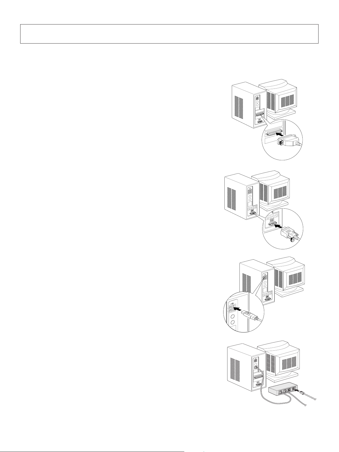
3-1. Connecting the Cable to the PC ...................................................................................................4
3-2. Connecting the Cable to the Printer .............................................................................................5
3-3. Installing the Printer Software .....................................................................................................8
3-4. Connecting the Optional AC Adapter ..........................................................................................9
3-5. Turning Power On ......................................................................................................................10
3-6. Connecting to a Peripheral Unit .................................................................................................11
3-7. Loading the Paper Roll ..............................................................................................................12
4. Attaching the Accessories ......................................................................................................................16
4-1. Attaching the Holder Plate .........................................................................................................16
4-2. Attaching the Rubber Feet .........................................................................................................17
4-3. Switch Cover Installation ...........................................................................................................18
5. Consumable Parts and AC Adapter .....................................................................................................19
5-1. Thermal Paper Roll ....................................................................................................................19
5-2. AC adapter (option)....................................................................................................................20
6. Control Panel and Other Functions .....................................................................................................21
6-1. Control Panel..............................................................................................................................21
6-2. Errors ..........................................................................................................................................21
6-3. Self-Printing ...............................................................................................................................23
7. Adjusting the Near-end Sensor .............................................................................................................24
8. Preventing and Clearing Paper Jams ...................................................................................................26
8-1. Preventing Paper Jams ...............................................................................................................26
8-2. Removing Paper Jam .................................................................................................................26
8-3. Releasing a Locked Cutter (Auto Cutter Mode only) ................................................................27
9. Periodical Cleaning ................................................................................................................................28
9-1. Cleaning the Thermal Head .......................................................................................................28
9-2. Cleaning the Rubber Roller .......................................................................................................28
9-3. Cleaning the Paper Holder and the Surrounding Area ...............................................................28
10. Specifications ........................................................................................................................................29
10-1. General Specifications ................................................................................................................29
10-2. Auto Cutter Specifications .........................................................................................................30
10-3. Interface .....................................................................................................................................30
10-4. Electrical Characteristics (AC adapter) ......................................................................................30
10-5. Environmental Requirements .....................................................................................................31
10-6. Reliability Specifications ...........................................................................................................32
11. Dip Switch Setting ................................................................................................................................33
11-1. Parallel Interface Model .............................................................................................................34
11-2. RS-232C Interface Model ..........................................................................................................36
11-3. USB Interface Model .................................................................................................................39
11-4. EthernetInterface Model ............................................................................................................41

12. Parallel Interface ..................................................................................................................................44
13. RS-232C Serial Interface .....................................................................................................................45
13-1. Interface Specifications ..............................................................................................................45
13-2. RS-232C Connector ...................................................................................................................46
13-3. Cable Connections .....................................................................................................................48
14. USB and Ethernet Interface ................................................................................................................49
15. Peripheral Unit Drive Circuit .............................................................................................................50
16. Memory Switch Settings ......................................................................................................................52
17. Release History .....................................................................................................................................53
Please access the following URL
http://www.star-m.jp/eng/dl/dl02.htm
for the latest revision of the manual.

– 1 –
Note
Printer
Holding plate
Screws
Paper roll
Switch blind
Setup sheets
CD-ROM
Paper roll holder
Rubber feet
1. Unpacking and Installation
1-1.Unpacking
Aer unpacking the unit, check that all the necessary accessories are included in the package.
Note: e ferrite core and fastener provided with
your printer depend on your printer congura-
tion.
Fig.1-1Unpacking
If anything is missing, contact the dealer where you bought the printer and ask them to supply
the missing part. Note that it is a good idea to keep the original box and all the packing materials
just in case you need to pack the printer up again and send it somewhere at a later date.

– 2 –
1-2.Choosingaplacefortheprinter
Before actually unpacking the printer, you should take a few minutes to think about where
you plan to use it. Remember the following points when doing this.
P Choose a rm, level surface where the printer will not be exposed to vibration.
P e power outlet you plan to connect to for power should be nearby and unobstructed.
P Make sure that the printer is close enough to your host computer for you to connect
the two.
P Make sure that the printer is not exposed to direct sunlight.
P Make sure that the printer is well away from heaters and other sources of extreme
heat.
P Make sure that the surrounding area is clean, dry, and free of dust.
P Make sure that the printer is connected to a reliable power outlet. It should not be on
the same electric circuit as copiers, refrigerators, or other appliances that cause power
spikes.
P Make sure that the room where you are using the printer is not too humid.
WARNING
P Shut down your equipment immediately if it produces smoke, a strange odor, or unu-
sual noise. Immediately unplug the equipment and contact your dealer for advice.
P Never attempt to repair this product yourself. Improper repair work can be dangerous.
P Never disassemble or modify this product. Tampering with this product may result in
injury, re, or electric shock.

– 3 –
Interface connector
For connection to a
host computer.
Peripheral drive connector
Connects to peripheral units such
as cash drawers, etc.
Do not connect this to a telephone.
Power connector
For connection of the AC adapter.
Never unplug the AC adapter while
the printer is on.
Printer cover
Open this cover to
load or replace paper.
Cover open lever
Push this lever in the direction of the
arrow to open the printer cover.
Power switch
Used to turn on/off
power to the printer.
Control panel
Features LED indicators to
indicate printer status and
switches to operate the printer.
2. Parts Identication and Nomenclature
2-1.CutterModel
2-2.TearBarModel

– 4 –
3. Setup
3-1. Connecting the Cable to the PC
3-1-1. Parallel Interface Cable
Connect the parallel interface cable to a parallel port
of your PC.
3-1-2. RS-232C Interface Cable
Connect the RS-232C interface cable to a RS-232C
port of your PC.
3-1-3. USB Interface Cable
Connect the USB interface cable to a USB port of
your PC.
3-1-4. Ethernet Interface cable
Connect the ethernet interface cable to a ethernet port
of your PC.

– 5 –
Parallel interface
cable
3-2. Connecting the Cable to the Printer
Note that the interface cable is not provided. Please use a cable that meets specifications.
CAUTION
Before connecting/disconnecting the interface cable, make sure that power to the printer and
all the devices connected to the printer is turned off. Also make sure the power cable plug is
disconnected from the AC outlet.
3-2-1. Parallel Interface Cable
(1) Make sure the printer is turn off.
(2) Affix the ferrite core onto the cable as shown in
the illustration.
(3) Pass the fastener through the ferrite core.
(4) Loop the fastener around the cable and lock it.
Use scissors to cut off any excess.
(5) Connect the interface cable to the connector on
the rear panel of the printer.
(6) Fasten the connector clasps.
Ferrite core
Interface cable
5 cm
(maximum)
Fastener

– 6 –
RS-232C
interface
cable
3-2-2. RS-232C Interface Cable
(1) Make sure the printer is turn off.
CAUTION
Before connecting/disconnecting the interface cable, make sure that power to the printer and
all the devices connected to the printer is turned off. Also make sure the power cable plug is
disconnected from the AC outlet.
(2) Connect the interface cable to the connector on the rear panel of the printer.
(3) Tighten the connector screws.
3-2-3. USB Interface Cable
Affix the ferrite core onto the USB cable as shown in
the illustration below and make sure to pass the cable
through the cable support as shown in the illustration.
4 cm (maximum)

– 7 –
(1) Make sure the printer is turned off.
(2) Install the ferrite core onto the ethernet cable as shown
in the illustration below.
(3) Pass the fastener through the ferrite core.
(4) Loop the fastener around the cable and lock it. Use scis-
sors to cut off any excess.
(5) Connect the interface cable to the connector on the rear
panel of the printer.
10 cm
(maximum)
Fastener
Ferrite core
Ethernet cable
3-2-4. Connecting Ethernet Cable
If a ferrite core is included, install the ferrite core onto the Ethernet cable according to the fol-
lowing procedure to prevent electrical noise.
If a ferrite core is not included, perform steps (1) and (5) only.
When using an Ethernet cable that is 10 m or less, shielded cable is recommended.
Ethernet interface board
IFBD-HE07
Ethernet interface board
IFBD-HE05

– 8 –
3-3.InstallingthePrinterSoftware
Here is the procedure for installing the printer driver and utility soware, which are stored on
the supplied CD-ROM.
e procedure applies to the Windows operating systems shown below.
• Windows XP (SP2 or later)
• Windows Vista
• Windows 7
(1) Turn ON the power to your PC to start Windows.
(2) Insert the supplied CD-ROM (Drivers and Utilities) into the
CD-ROM drive.
(3) Follow the instructions that appear on the screen.
(4) e dialog shown in the illustration indicates that the pro-
cedure has been completed.
Click “Finish”.
e dialog that appears on the screen varies with your system. is completes the installation of
the printer soware. A message will appear, prompting you to restart. Restart Windows.
.

– 9 –
3-4.ConnectingtheOptionalACAdapter
Note: Before connecting/disconnecting the AC adapter, make sure that power to the
printer and all the devices connected to the printer is turned o. Also make sure the
power cable plug is disconnected from the AC outlet.
(1) Connect the AC adapter to the power cable.
Note: Use only the standard AC adapter and power cable.
(2) Connect AC adapter to the connector on the printer.
(3) Insert the power cable plug into an AC outlet.
CAUTION
When disconnecting the cable, take hold of the cable
connector to pull it out. Releasing the lock makes
it easy to disconnect the connector.
Pulling the cable excessively could cause damage
to the connector.

– 10 –
Power switch
3-5.TurningPowerOn
Make sure that the Power cord has been connected as described in 3-4.
Turn ON the power switch located on the front of the printer.
e POWER lamp on the control panel will light up.
CAUTION
We recommend that you unplug the printer from the power outlet whenever you do not
plan to use it for long periods. Because of this, you should locate the printer so that the
power outlet it is plugged into is nearby and easy to access.
When an Switch blind is afxed to the printer above the power switch, the ON/OFF
marks of the power switch may be hidden. If this occurs, remove the power cord from
the outlet to turn the printer OFF.

– 11 –
3-6.ConnectingtoaPeripheralUnit
You can connect a peripheral unit to the printer using a modular plug. See “Modular plug” on
page 50 for details about the type of modular plug that is required. Note that this printer does
not come with a modular plug or wire, so it is up to you to obtain one that suits your needs.
CAUTION
Make sure that the printer is turned off and unplugged from the AC outlet and that the
computer is turned off before making connections.
Connect the peripheral drive cable to the connector on the rear panel of the printer.
CAUTION
Do not connect a telephone line into the peripheral drive connector. Failure to observe
this may result in damage to the printer.
Also, for safety purposes, do not connect wiring to the external drive connector if there
is a chance it may carry peripheral voltage.

– 12 –
Cover open lever
Paper roll
Tear Bar Model
1) Push the cover open lever, and open the printer
cover.
2) While observing the direction of the roll, set the
paper roll into the hollow, and pull on the leading
edge of the paper toward you.
CAUTION
Do not pull out the end of the paper diagonally,
as it will cause the paper to become jammed
or skewed.
3) Push down both sides of the printer cover to
close.
Note: Make sure that the printer cover is securely
closed.
4) TearBarModel:
Tear o the paper as shown.
AutoCutterModel:
If the printer cover is closed aer turning on the
power, the cutter operates automatically and the
front end of the paper is cut.
3-7.LoadingthePaperRoll
3-7-1. Using79.5mmWidthPaperRoll
Be sure to use roll paper that matches the printer’s specication.
When using a paper roll with an 57.5 mm width, install the paper roll holder as described on
the following page.

– 13 –
A
Paper Guide
3-7-2. Using57.5mmWidthPaperRoll
When using a paper roll with 57.5 mm width, install the supplied paper guide on the printer.
To change the eective print width (roll paper width), change the setting at memory switch
conguration Utility. For details on the setting of the memory switches, refer to the soware
manual located in the “Documents” folders on the CD-ROM.
1 Insert the paper guide along the groove in the unit as shown.
2 Insert the paper guide by pushing the area marked “A” down until it clicks into place.
Note: Aer using a paper roll with a width of 57.5 mm, do not change to a paper roll
with a width of 79.5. (is is because the printer head has deteriorated as a result of
a portion of the head having been in direct contact with the platen.)

– 14 –
WARNING
1) Do not touch the cutter blade.
• There is a cutter inside the paper outlet slot. Not only should you not put your
hand in the paper outlet slot while printing is in progress, never put your hand
into the outlet even when printing is not in progress.
• The printer cover can be opened when replacing the paper. However, since the
cutter blade is on the inside of the printer cover, be careful not to place your face
or hands too close to the cutter blade.
2) During and immediately after printing, the area around the thermal head is very
hot. Do not touch it, as you could be burned.
CAUTION
1) Do not operate the cover open lever while pressing on the printer cover with your
hand.
2) Do not push the cover open lever and open the printer cover when printing is in
progress or when the auto cutter is operating.
3) Do not push out paper while the printer cover is closed.
4) The heating element and the driver IC of the thermal head are easily damaged. Do
not touch them with metal objects, sandpaper, etc.
5) Printing quality may suffer if the thermal head heating element becomes soiled by
being touched with your hands. Do not touch the thermal head heating element.
6) There is a risk of damage to the driver IC of the thermal head from static electricity.
Never directly touch the IC.
7) The printing quality and working life of the thermal head cannot be guaranteed if
any paper other than that recommended is used. In particular, paper containing
[Na+, K+, C1-] may drastically reduce the working life of the thermal head. Please
exercise caution.
8) Do not operate the printer if there is moisture on the front surface of the head from
condensation, etc.
CautionSymbol
These labels are located near the thermal print head.
Because the thermal print head is hot immediately after printing, do not touch
it. Static electricity can damage the thermal print head. To protect the thermal
print head from static electricity, do not touch it.
This symbol is placed near the cutter.
Never touch the cutter blade, as you could injure your fingers.
This symbol is placed near the peripheral drive connector.
Do not connect this to a telephone.

– 15 –
9) A printed piece of thermal paper may become electrically charged. If the printer is
placed vertically or mounted on a wall, the cut piece of paper may stick to the printer,
instead of falling. Beware that this could cause a problem if you use a stacker that
stores the pieces of paper that fall freely.
10) Do not change the paper width during use. The thermal printing head, rubber roller,
and cutter wear differently according to the paper width. This can cause the printing
or cutter movement to malfunction.
11) Do not transport the printer with its cover open and holding it by the cover.
12) Do not forcibly pull on the interface cable, power cable, or cash drawer cable that is
connected. To detach a connector, make sure to grasp it at the connector portion,
without applying excessive stress on the connector at the printer.
Notes on Using the Auto Cutter
1) To print after a cut, feed 1 mm (8-dot line) or more of paper.
2) If the cutter is not in its home position after an error, rst eliminate the cause of the
error; then, turn the power back ON.
3) A margin of 5 mm or more is recommended from the end of the printed area to the
cutting position.
4) Do not attempt to remove the paper during a cut, as this can cause a paper jam.

– 16 –
4. Attaching the Accessories
The following accessories are necessary when mounting the printer to a wall.
• Holder plate and two flangeless screws
The following accessories are necessary when positioning the printer vertically.
• Four rubber feet
The following accessories do not necessarily have to be attached. Attach it if necessary.
• Switch cover
4-1. Attaching the Holder Plate
• The holder plate is attached to the printer using the included screws and is hooked onto
screws that are installed into the wall.
• The screws on the wall are not included.
Use commercially available screws (4 mm diameter) that are suitable for the wall
material (wood, steel beam, concrete, etc.).
• The printer’s weight is approximately 2.4 kg when the largest diameter roll paper is
loaded.
Use screws on the wall that have both shear strength and pulling-out strength to
withstand a force of at least 12 kgf (118 N).
Precautions regarding installation
CAUTION
This caution indicates information that, if ignored, could lead to personal injury or property
damage.
• Be sure to have qualified personnel install the specified screws and printer to the wall.
Star is not responsible for any accidents or injuries that occur as a result of improper
installation, misuse, or modifications.
Especially when installing the printer at a high location, make sure that the printer is
securely installed to the wall.
If the printer is not installed securely and falls, personal injury or damage to the printer
may result.
• Make sure that the mounting surface and installation screws are strong enough to install
the printer.
Securely install the printer so that the weight of the printer and any connected cables will
not cause the printer to fall.
Otherwise, personal injury or damage to the printer may result.
• Do not install the printer in an unstable location or a location that is exposed to vibration
and shocks.
If the printer falls, personal injury or damage to the printer may result.
Other manuals for TSP650 SERIES
3
Table of contents
Other Star Printer manuals

Star
Star TSP800II SERIES User manual

Star
Star TSP400 SERIES User manual

Star
Star SM-T300 User manual

Star
Star Star NX-350 User manual

Star
Star TSP700 SERIES User manual

Star
Star SM-T300DB Series User manual

Star
Star LC-7211 User manual

Star
Star SM-T300 User manual

Star
Star LC-90 User manual

Star
Star TSP200 Series User manual

Star
Star LC-8521 User manual

Star
Star SM-T300I Series User manual

Star
Star AR-1000 User manual

Star
Star FVP-10U User manual

Star
Star LaserPrinter 4 Instructions for use

Star
Star SM-T300 User manual

Star
Star SP712R series User manual

Star
Star TSP654II Series User manual

Star
Star SP700 Series User manual

Star
Star TSP800II SERIES User manual