stayer CD125 User manual

www.grupostayer.com
ES
IT
GB
FR
P
TR
PL
Manual de instrucciones
Istruzioni d’uso
Operating instructions
Instructions d´emploi
Manual de instruções
Instrukcja obsługi
Kullanma Kılavuzu
Área Empresarial Andalucía - Sector 1
C/ Sierra de Cazorla, 7
28320 - Pinto (Madrid) SPAIN
Email: sales@grupostayer.com
Email: info@grupostayer.com
CD125
CD180K
Bedienungsanleitung

2
2

3
3

6.1.
CD 125 CD 180 K
W 1500 1800
min-1 8500 4100
mm Ø 125 x 22,2 Ø 180 x 5/8”
mm 8 - 30 9 - 51
mm 5 - 26 15 - 54
II II
Kg 5 7.7
K=3 dB
LpA dB(A) 97 99
LWA dB(A) 108 110
K=1.5 m/s2ahm/s23 3.5
x
y
Ø
Ø

ENGLISH
5
5
This manual is consistent with the date of manufacture of
your machine, you will nd information on the technical
data of the machine acquired manual check for updates
of our machines on the website: www.grupostayer.com
1. Contents page
2. Specic safety instructions...........................20
3. Instructions for use........................................21
3.1 Placement Tool ................................................... 21
3.2 Assembly............................................................. 21
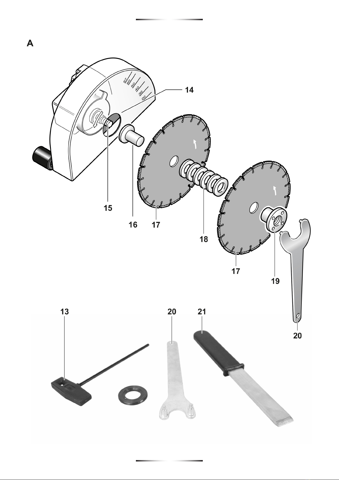
3.3 Illustrated description.......................................... 22
4. Operating instructions...................................23
4.1 Placement and testing ........................................ 23
4.2.Mains connection................................................ 23
4.3 Operation adjustment.......................................... 23
4.4 General instructions for use................................ 23
5. Maintenance and service instructions ......... 24
5.1 Repair service..................................................... 25
5.2 Warranty ............................................................. 25
5.3 Disposal and recycling........................................ 25
6. Regulations.....................................................25
6.1 Technical Data .................................................... 25
6.2 EU declaration of conformity............................... 26
2. Specic safety instructions
Read all safety warnings, instructions,
illustrations and specications provided
with this power tool. Failure to follow all
instructions listed below may result in electric
shock, re and/or serious injury.
Always use guard provided with the tool. The guard
must be securely attached to the power tool and
positioned for maximum safety, so the least amount
of wheel is exposed towards the operator. Position
yourself and bystanders away from the plane of the
rotating wheel. The guard helps to protect operator
from broken wheel fragments and accidental contact with
wheel.
Use only diamond cut-o wheels for your power tool.
Just because an accessory can be attached to your power
tool, it does not assure safe operation.
The rated speed of the accessory must be at least
equal to the maximum speed marked on the power
tool.Accessories running faster than their rated speed
can break and y apart.
Wheels must be used only for recommended
applications. For example: do not grind with the side
of cut-o wheel. Abrasive cuto wheels are intended for
peripheral grinding, side forces applied to these wheels
may cause them to shatter.
Always use undamaged wheel anges that are of
correct diameter for your selected wheel. Proper wheel
anges support the wheel thus reducing the possibility of
wheel breakage.
The outside diameter and the thickness of your
accessory must be within the capacity rating of your
power tool. Incorrectly sized accessories cannot be
adequately guarded or controlled.
The arbour size of wheels and anges must properly
t the spindle of the power tool. Wheels and anges with
arbour holes that do not match the mounting hardware of
the power tool will run out of balance, vibrate excessively
and may cause loss of control.
Do not use damaged wheels. Before each use, inspect
the wheels for chips and cracks. If power tool or
wheel is dropped, inspect for damage or install an
undamaged wheel. After inspecting and installing the
wheel, position yourself and bystanders away from
the plane of the rotating wheel and run the power tool
at maximum no load speed for one minute. Damaged
wheels will normally break apart during this test time.
Wear personal protective equipment. Depending on
application, use face shield, safety goggles or safety
glasses. As appropriate, wear dust mask, hearing
protectors, gloves and workshop apron capable of
stopping small abrasive or workpiece fragments.
The eye protection must be capable of stopping ying
debris generated by various operations. The dust mask or
respirator must be capable of ltrating particles generated
by your operation. Prolonged exposure to high intensity
noise may cause hearing loss.
Keep bystanders a safe distance away from work area.
Anyone entering the work area must wear personal
protective equipment. Fragments of workpiece or of a
broken accessory may y away and cause injury beyond
immediate area of operation.
Hold power tool by insulated gripping surfaces only,
when performing an operation where the cutting
accessory may contact hidden wiring or its own cord.
Cutting accessory contacting a “live” wire may make
exposed metal parts of the power tool “live” and shock the
operator.
Position the cord clear of the spinning accessory. If
you lose control of the power tool, the cord may be cut
or snagged and your hand or arm may be pulled into the
spinning accessory.
Never lay the power tool down until the accessory
has come to a complete stop. The spinning accessory
may grab the surface and pull the power tool out of your
control.
Do not run the power tool while carrying it at your side.
Accidental contact with the spinning accessory could snag
your clothing, pulling the accessory into your body.

ENGLISH
6
6
Regularly clean the power tool’s air vents. The motor’s
fan will draw the dust inside the housing and excessive
accumulation of powdered metal may cause electrical
hazards.
Do not operate the power tool near ammable
materials. Sparks could ignite these materials.
Do not use accessories that require liquid coolants.
Using water or other liquid coolants may result in
electrocution or shock.
Kickback and related warnings
Kickback is a sudden reaction to a pinched or snagged
rotating wheel. Pinching or snagging causes rapid stalling
of the rotating wheel which in turn causes the uncontrolled
power tool to be forced in the direction opposite of the
wheel’s rotation at the point of the binding.
Maintain a rm grip on the power tool and position
your body and arm to allow you to resist kickback
forces. Always use auxiliary handle, if provided, for
maximum control over kickback or torque reaction
during start-up. The operator can control torque reactions
or kickback forces, if proper precautions are taken.
Never place your hand near the rotating accessory.
Accessory may kickback over your hand.
Do not position your body in the area where power
tool will move if kickback occurs. Kickback will propel
the tool in direction opposite to the wheel’s movement at
the point of snagging.
Use special care when working corners, sharp edges,
etc. Avoid bouncing and snagging the accessory.
Corners, sharp edges or bouncing have a tendency to
snag the rotating accessory and cause loss of control or
kickback.
Do not attach a saw chain woodcarving blade or
toothed saw blade. Such blades create frequent kickback
and loss of control over the power tool.
Do not “jam” the cut-o wheel or apply excessive
pressure. Do not attempt to make an excessive depth
of cut. Overstressing the wheel increases the loading and
susceptibility to twisting or binding of the wheel in the cut
and the possibility of kickback or wheel breakage.
When wheel is binding or when interrupting a cut
for any reason, switch o the power tool and hold
the power tool motionless until the wheel comes to
a complete stop. Never attempt to remove the cut-
o wheel from the cut while the wheel is in motion
otherwise kickback may occur. Investigate and take
corrective action to eliminate the cause of wheel binding.
Do not restart the cutting operation in the workpiece.
Let the wheel reach full speed and carefully reenter
the cut. The wheel may bind, walk up or kickback if the
power tool is restarted in the workpiece.
Support panels or any oversized workpiece to
minimize the risk of wheel pinching and kickback.
Large workpieces tend to sag under their own weight.
Supports must be placed under the workpiece near the
line of cut and near the edge of the workpiece on both
sides of the wheel.
Use extra caution when making a “pocket cut” into
existing walls or other blind areas. The protruding
wheel may cut gas or water pipes, electrical wiring or
objects that can cause kickback.
Additional safety warnings
Wear safety goggles.
Use suitable detectors to determine if utility lines
are hidden in the work area or call the local utility
company for assistance. Contact with electric lines can
lead to re and electric shock. Damaging a gas line can
lead to explosion. Penetrating a water line causes property
damage or may cause an electric shock.
When working stone, use dust extraction. The vacuum
cleaner must be approved for the extraction of stone
dust. Using this equipment reduces dust-related hazards.
When working with the machine, always hold it rmly
with both hands and provide for a secure stance. The
power tool is guided more secure with both hands.
Secure the workpiece. A workpiece clamped with
clamping devices or in a vice is held more secure than
by hand.
Never use the machine with a damaged cable. Do not
touch the damaged cable and pull the mains plug
when the cable is damaged while working. Damaged
cables increase the risk of an electric shock.
3. Instructions for use
3.1 Placement tool
While reading the operating instructions, unfold the
graphics page for the machine and leave it open.
In conjunction with a vacuum cleaner and with rm support
of the cutting guide, the machine is intended to cut or slot
mainly mineral materials such as reinforced concrete,
brickwork and road surfaces without the use of water.
3.2 Assembly
Before any work on the machine itself, pull the
mains plug.
Dust extraction

ENGLISH
7
7
Dusts from materials such as lead-containing coatings,
some wood types, minerals and metal can be harmful to
one’s health. Touching or breathing-in the dusts can cause
allergic reactions and/or lead to respiratory infections of
the user or bystanders.
Some dusts are regarded as carcinogenic. Materials
containing asbestos may only be worked by specialists.
– Use dust extraction whenever possible.
– Provide for good ventilation of the working place.
– It is recommended to wear a P2 lterclass respirator.
Observe the relevant regulations in your country for the
materials to be worked. The vacuum cleaner must be
approved for the extraction of masonry dust. STAYER
provides suitable vacuum cleaners.
The machine can be plugged directly into the receptacle
of a STAYER all-purpose vacuum cleaner with remote
starting control. The vacuum cleaner starts automatically
when the machine is switched on.
Mount the elbow 11 (optional) onto the vacuum connection
10 and connect a vacuum hose 12 (accessory). Connect
the vacuum hose 12 with a vacuum cleaner (accessory).
An overview for the connection of various vacuum cleaners
can be found at the end of these instructions.
Mounting the Auxiliary Handle
Depending on the working manner, screw the auxiliary
handle 4 to the left on the auxiliary- handle holder.
Mounting Diamond Cutting Discs
When mounting and replacing diamond cutting
discs, it is recommended to wear protective
gloves.
Diamond cutting discs become very hot during
operation; do not touch them until they have
cooled down.
Place the power tool on its side so that the cutting-depth
scale 2 can be seen. Loosen clamping lever 9 and adjust
the least cutting depth.
Dismounting the Clamping Assembly (see gure A)
Loosen the knobs 9 and remove the protective cap 22.
Press the spindle lock button 7 to lock the grinding spindle.
Actuate the spindle lock button only when the
grinder spindle is at a standstill. Otherwise,
the machine may become damaged.
Loosen the clamping nut 19 with the two-pin spanner 20
and unscrew the clamping nut 19. Remove the spacer
discs 18 and the mounting ange 16. Clean the grinder
spindle 15 and all parts to be mounted.
Determining the Slot Width
The slot width results from the amount of spacer discs 18
between the two diamond cutting discs 17 (not included)
and the cutting width of the diamond cutting discs.
The machine can be operated with one or two diamond
cutting discs.
Mounting the Clamping Assembly (see gure A)
Set the mounting ange 16 onto the grinder spindle 15.
The mounting ange with its driving feature must be
properly seated on the grinding spindle.
If the disc has rotational direction indication
(arrow) mount the disk so that the arrow on
the head 6 coincides with the arrow on the
disc.
Place the diamond cutting disc 17 (not included) and the
spacer discs 18on the mounting ange 16.
Regardless of the requested slot width, all
spacer discs 18 provided must always be
mounted. Otherwise, the diamond cutting disc 17
(not included) can become loose during operation and
lead to injuries.
Place the protective cover 22 and tighten the knobs 9.
At least one spacer disc 18 must be mounted between two
diamond cutting discs 17 (not included).
When mounting the diamond cutting discs, ensure that the
direction-of-rotation arrows on the diamond cutting discs
match with the rotation rotation direction of the machine
(see direction of rotation arrow on the gear case).
Press the spindle lock button 7 to lock the grinding spindle.
Screw on the clamping nut 19 and tighten it with the two-
pin spanner 20.
When working with 2 diamond cutting discs 17 (not
included), always replace them in pairs. See graphics
page for the mounting sequence.
The mounted diamond cutting discs 17
protrude out of the protection guard, even at
the least preselected cutting depth. Therefore,
never set down the machine on the chaser rollers 3,
but always aside.
3.3 Illustrated description
1 On/O switch
2 Cutting-depth scale
3 Baking roll
4 Auxiliary handle
5 Brush cover
6 Rotation indicator
7 Spindle lock button
8 Protection guard with cutting guide
9 Clamping lever for depth stop adjustment
10 Vacuum connection

ENGLISH
8
8
11 Elbow*
12 Vacuum hose*
13 Service key
14 Screw lever for protection guard
15 Grinder spindle
16 Mounting ange
17 Diamond cutting disc*
18 Spacer discs
19 Clamping nut
20 Two-pin spanner for clamping nut*
21 Break-out tool*
22 Protective cover disk.
23 Safety button lock / unlock switch.
*Accessories shown or described are not part of the standard
delivery scope of the product. A complete overview of accessories
can be found in our accessories program.
4. Operating instructions
4.1 Placement and testing
Observe correct mains voltage! The voltage of
the power source must agree with the voltage
specied on the nameplate of the machine.
Power tools marked with 230 V can also be
operated with 220 V.
Switching On and O
Before starting the unit, place the unit on the
motor body, so that the diamond cutting discs
do not reach to touch the workpiece.
Otherwise, the diamond cutting discs can touch the
workpiece, resulting in possible loss of control over the
power tool when switching on.
For the implementation of the machine press the unlock
button switch 23 and then press the trigger on / o 1.
To switch o the power tool, release the On/O switch 1.
Never set down a coasting machine on the
chaser rollers 3, but always aside, so that the
diamond cutting discs can rotate freely and do
not face toward your body.
Check the diamond cutting discs before use.
The diamond cutting disc(s) must be mounted
properly and be able to rotate freely. Carry out
a test run for at least one minute without any
load. Do not use diamond cutting discs that are
damaged, outofbalance, or vibrate. Damaged diamond
cutting discs can rupture and lead to injuries.
4.2 Mains connection
Reduced starting current
The electronic reduced starting current limits the power
consumption when switching the tool on and enables
operation from a 13 ampere fuse.
4.3 Operation adjustment
Pre-selecting the Cutting Depth
The cutting depth may only be pre-selected
when the machine is switched o.
Loosen clamping lever 9 and adjust the desired cutting
depth according to the cutting-depth scale 2. Afterwards,
tighten clamping lever 9 again.
4.4 General instructions for use
Please observe the following notes in order to reduce the
dust emissions occurring while working.
– Use only the combinations of wall chaser and
dustcategory M vacuum cleaner recommended by
STAYER. Other combinations can lead to insucient dust
collection and separation.
– Observe the operating instructions of the vacuum cleaner
for maintenance and cleaning of the vacuum cleaner,
including the lter. Empty dust collection containers
immediately once full. Clean the lters of the vacuum
cleaner regularly and always insert the lters completely
into the vacuum cleaner.
– Only use vacuum hoses as intended for by STAYER. Do
not manipulate the vacuum hose. When rocks or chunks
of stone/masonry are drawn into the vacuum hose, cease
work and clean the vacuum hose immediately. Prevent
the vacuum hose from being bent or creased.
– Use the wall chaser only according to its intended use.
– Only use tools that are in perfect condition. Decrease in
work progress is noticeable whilst using worn tools.
– Observe the general requirements for construction sites.
– Provide for good ventilation.
– Ensure that the working range/area is free of obstructions.
For longer slots, the vacuum cleaner must be guided along
in time, without obstructions in the path.
– Wear hearing protection, protective goggles, dust mask
and gloves as required. As dust mask, use at least a
particle-ltering class FFP2 half-mask.
– Use a suitable vacuum cleaner for cleaning the
workplace. Prevent settled dust from being swirled up by
sweeping.
Exercise caution when cutting slots in
structural walls.
Do not strain the machine so heavily that it
comes to a standstill.
Clamp the workpiece if it does not remain
stationary due to its own weight.

ENGLISH
9
9
The machine may only be used for dry cutting.
Always guide the machine with both handles.
Do not guide or carry the machine by the
elbow.
Adjust the cutting depth.
To compensate inaccuracies that occur when breaking
away the n, the cutting depth must be set approx. 3 mm
deeper than the requested slot depth.
– Place the power tool in such a manner on both rear
chaser rollers 3, that the diamond cutting discs do not
touch the workpiece.
– Switch the machine on and slowly plunge into the
material.
– Guide the machine with both handles, applying moderate
feed, suited to the material being worked.
– The machine must always work in an upgrinding
motion. Otherwise, the danger exists of it being pushed
uncontrolled out of the cut.
– The machine can be both pushed or pulled in the cutting
direction. Vertical slots can easily be cut by pulling the
machine from top to bottom.
– After nishing the working procedure, swivel the diamond
cutting discs out of the slot with the machine still running.
– Switch the power tool o.
Do not brake coasting diamond cutting discs by applying
sideward pressure.
Never set down a coasting machine on the
chaser rollers 3, but always aside, so that the
diamond cutting discs can rotate freely and do
not face toward your body.
Diamond cutting discs become very hot during
operation; do not touch them until they have
cooled down.
Remove the remaining n of the material with the break-
out tool 21.
Curved cuts are not possible, as the diamond cutting discs
could jam in the material.
When cutting through plate materials, ensure that the
materials are rmly backed on a surface or supported.
When breaking through walls, e. g. with a rotary hammer,
most of the chipping-o of the surface material can be
avoided by rst cutting in a slot with maximum cutting
depth.
For cutting expecially hard material, e. g., concrete
with high pebble content, the diamond cutting disc can
overheat and become damaged as a result. This is clearly
indicated by circular sparking, rotating with the diamond
cutting disc.
In this case, interrupt the cutting process and allow the
diamond cutting disc to cool by running the machine for a
short time at maximum speed with no load.
Noticeable decreasing work progress and circular sparking
are indications of a diamond cutting disc that has become
dull. Briey cutting into abrasive material (e. g. lime-sand
brick) can resharpen the disc again.
Information on Structures
Slots in structural walls are subject to the Standard, or
country-specic regulations.
These regulations are to be observed under all
circumstances.
Before beginning work, consult the responsible structural
engineer, architect or the construction supervisor. The
permitted slot depth and width depends on the slot length,
wall thickness and the building material used.
5. Maintenance and service instructions
Before any work on the machine itself, pull the
mains plug.
For safe and proper working, always keep the
machine and ventilation slots clean.

ENGLISH
10
10
After nishing work, dismount the clamping xtures and
clean all clamping parts as well as the protective cover.
If the machine should fail despite the care taken in
manufacturing and testing procedures, repair should be
carried out by an after-sales service centre for STAYER
power tools.
5.1 Repair service
Our after-sales service responds to your questions
conceming maintenance and repair ofyour product as well
as spare parts. Exploded views and information on spare
parts can also be found under:
info@grupostayer.com
Our customer consultants answer your questions
conceming best buy, application and adjustment of
productsand accessories.
5.2 Warranty
Warranty card
lncluded in the documentation that accompanies this
equipment, you should nd the warranty card. You should
ll out the card completely and retum to vendar with a copy
of purchasing receipt or invoice and you should receive a
receipt.
Note: lf you cannot nd the warranty card within the
documentation,youmust ask for it through your supplier.
The warranty is limited only to manufacturing defects and
expire if pieces have been removed or manipulated or
repaired otherthan themanufacturer.
5.3 Disposal and recycling
The machine, accessories and packaging should be
sorted for environmental-friendly recycling.
Only for EC countries:
Do not dispose of power tools into household waste!
According the European Guideline 2012/19/
UE for Waste Electrical and Electronic
Equipment and its implementation into national
right,power tools that are no longer usable
must be collected separately and disposed of
in an environmentally correct manner.
Subject to change wlthout notlce.
6. Regulations
6.1 Technical Data
Ø
Ø
x
y
= Power input
=No Load speed
= Disc Dimension
= Kerf width.
= Cutting depth.
= Protection class
= Weight
LWA = Sound power level
LPA = Sound pressure level
= Vibration
The values givenarevalid for nominalvoltages [U]230/240
V-50/60 Hz - 110/120 V - 60Hz. For lower voltage and
models for specic countries, these values can vary.
Please observe the article number on the type plata of
your machine.The trade names of the individual machines
may vary.
Noise/ Vibration lnformation
Measured sound values determined according to EN
60745. Typically the A-weighted noise levels of the product
are: Sound pressure level 97 dB(A); Sound power level
108 dB(A). Uncertainty K=3 dB.
Wear hearing protection!
Vibration total values (triax vector sum) determined
according to EN 60745: Vibration emission value ah=
9.0m/s2, Uncertainty K =2.0 m/s2.
The vibration emission level given in this information sheet
has been measured in accordance with a standardised
test given in EN 60745 and may be used to compare
one tool with another. lt may be used for a preliminary
assessment of exposure.
The declared vibration emission level represents the
main applications of the tool. However if the tool is used
for dierent applications,with dierent accessories or
poorly maintained, the vibration emission may dier.
This may signicantly increase the exposure leveloverthe
totalworking period.
An estimation of the levelof exposure to vibration should
also take into account the times when the tool is switched
o or when it is running but not actually doing the job. This
may signicantly reduce theexposure level over the total
working period.
ldentify additional safety measures to protect the operator
from the eects of vibration such as: maintain the tool and
the accessories,keepthe hands warm, organisation of
work pattems.

ENGLISH
11
11
6.2 EU declaration of conformity
The undersigned: STAYER IBERICA, S.A.
With address at:
Calle Sierra de Cazorla, 7
Área Empresarial Andalucía - Sector 1
28320 PINTO (MADRID)
Tel.:+34 91 691 85 16 / Fax: +34 91 691 91 72
CERTIFIES
That the machine:
Type: DIAMOND CHANNELCUTTER
Models: CD180K / CD125
We declare under our responsibility that the product
described under “Technical Data” is in accordance with
the following standards or standardized documents:
EN 60745-1, EN 15027, EN 55014-1, EN 55014-2, EN
61000-3-2, EN 61000-3-3 according to EU Regulations
2006/42/EC, 2014/30/EU, 2011/65/EU.
September 5, 2017
Ramiro de la fuente
Managing Director

www.grupostayer.com
Área Empresarial Andalucía - Sector 1
C/ Sierra de Cazorla, 7
28320 - Pinto (Madrid) SPAIN
Email: sales@grupostayer.com
Email: info@grupostayer.com
Other manuals for CD125
1
This manual suits for next models
1
Table of contents
Other stayer Power Tools manuals

stayer
stayer BHL112K User manual

stayer
stayer S110PE User manual

stayer
stayer CD125 User manual

stayer
stayer PR10E User manual

stayer
stayer HDB L20 User manual

stayer
stayer PR6 User manual

stayer
stayer MULTITOOL PRO 300 User manual

stayer
stayer PR10EK User manual

stayer
stayer ISL20 User manual

stayer
stayer BHL112K User manual

stayer
stayer ISL122K User manual

stayer
stayer PRO 300 User manual

stayer
stayer DWS L20 User manual

stayer
stayer BHL112BK User manual

stayer
stayer MULTI RAZER 85 User manual

stayer
stayer CD150K User manual

stayer
stayer ISL120K User manual

stayer
stayer SUH2000E User manual

stayer
stayer IW 550 User manual

stayer
stayer CS85 User manual