manuals.online logo
Brands
  1. Home
  2. •
  3. Brands
  4. •
  5. Steinhof
  6. •
  7. Automobile Accessories
  8. •
  9. Steinhof F-301 Parts list manual

Steinhof F-301 Parts list manual

INSTRUKCJA
MONTA¯U I EKSPLOATACJI
ZACZEPU KULOWEGO DO :
SAMOCHODU
Ford Transit Custom
(Furgon, Minibus)
®(11/2012- ) Nr kat. F-301
PRZEZNACZENIE
Zaczep kulowy F-301 jest przeznaczony do holowania przyczepy. Zaczep
F-301
F-301
F-301
ten posiada aktualne
Œwiadectwo Homologacji uprawniaj¹ce do oznaczenia wyrobu znakiem homologacji E20.
WARUNKI MONTA¯U
Zaczep kulowy mo¿e byæ u¿ywany i eksploatowany w samochodzie o w³aœciwym stanie
technicznym elementów nadwozia. Zaczep musi byæ zamontowany i eksploatowany w samochodzie
zgodnie z niniejsz¹ instrukcj¹.
Wszystkie œruby i nakrêtki wystêpuj¹ce w zaczepie kulowym musz¹ byæ dokrêcone odpowiednim
momentem obrotowym (Mo) o wartoœciach podanych w poni¿szej tabeli (dla œrub w klasie 8.8):
WARUNKI EKSPLOATACJI
Zaczep kulowy posiada tabliczkê znamionow¹ okreœlaj¹c¹ prawid³owe i bezpieczne obci¹¿enie
zaczepu, tj. :
Si³ê Dwylicza siê ze wzoru:
Podczas eksploatacji poszczególne elementy zaczepu kulowego powinny byæ utrzymane w nale¿ytym
stanie technicznym i zabezpieczone przed dzia³aniem korozji. W czasie holowania przyczepa musi byæ
z³¹czona dodatkowym elastycznym z³¹czem o odpowiedniej wytrzyma³oœci (linka, ³añcuch). W czasie
eksploatacji zaczepu kulowego nale¿y okresowo sprawdzaæ po³¹czenia œrubowe, a w przypadku
poluzowania nakrêtek nale¿y je dokrêciæ.
MONTA¯
Zaczep kulowy sk³ada siê z nastêpuj¹cych elementów:
30.10.2015. Nr kat. F-301
M8 - 25 (Nm)
M10 - 50 (Nm)
M12 - 85 (Nm)
M16 - 200 (Nm)
Numer katalogowy zaczepu kulowego
Klasa zaczepu kulowego (urz¹dzenia sprzêgaj¹cego)
Nr œwiadectwa Homologacji zaczepu kulowego
Teoretyczna si³a odniesienia dzia³aj¹ca na zaczep kulowy
Max. dopuszczalne obci¹¿enie pionowe kuli zaczepu
Max. dopuszczalne obci¹¿enie holowanej przyczepy
Przestrzeganie niniejszej instrukcji zapewnia prawid³owy monta¿ i eksploatacjê
zaczepu kulowego F-301.
D= gx kN
TxR
T+R
T-technicznie dopuszczalna maksymalna masa, w tonach, pojazdu ci¹gn¹cego
(tak¿e ci¹gników holuj¹cych) ³¹cznie, jeœli wystêpuje, z obci¹¿eniem pionowym
przyczepy z osiê centraln¹.
R-technicznie dopuszczalna maksymalna masa, w tonach, przyczepy samochodowej
z dyszlem ruchomym w p³aszczyŸnie pionowej lub naczepy.
2
g- przyspieszenie ziemskie (przyjmowane jako 9,81 m/s )
Po zamontowaniu zaczepu kulowego F-301 nale¿y uzyskaæ wpis w dowodzie rejestracyjnym pojazdu.
UWAGA:
Wszystkie uszkodzenia mechaniczne
zaczepu kulowego F-301 wykluczaj¹ dalsz¹ jego eksploatacjê. Uszkodzony zaczep nie mo¿e byæ
naprawiany. W przypadku nie przestrzegania opisanego sposobu monta¿u lub niew³aœciwego jego
u¿ytkowania producent nie ponosi odpowiedzialnoœci za powsta³e szkody.
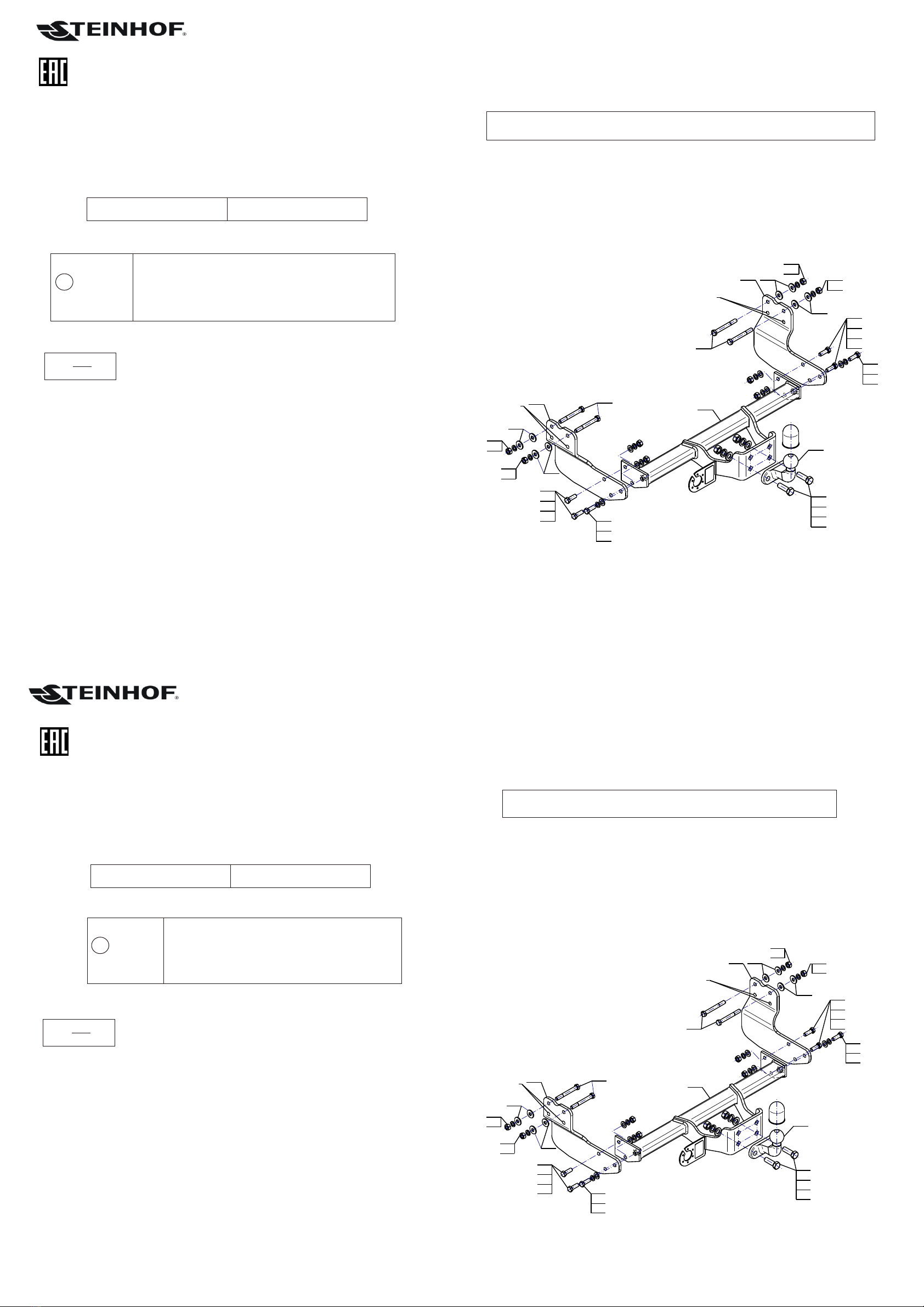
SCHEMAT MONTA¯U:
Sprawdzaæ po³¹czenia œrubowe po przejechaniu 1000 km. Kulê zawsze utrzymywaæ w
czystoœci i smarowaæ smarem sta³ym. Stosowaæ os³onê kuli.
1. Monta¿ zaczepu nie wymaga demonta¿u ani podcinania zderzaka tylnego.
2. Wykrêciæ oryginalne œruby z ramy w punktach A.
3. Przy³o¿yæ wsporniki (3, 4) do wewnêtrznych stron pod³u¿nic wraz z podk³adkami 30/ 12,5x3 (5)
i skrêciæ œrubami M12x100 (7) wraz z podk³adkami 30/ 12,5x3 (5), podk³adkami sprê¿ystymi
12,2 (9) i nakrêtkami M12 (13) oraz skrêciæ œrubami fabrycznymi w punktach A.
4. Pomiêdzy zamontowane wsporniki (3, 4) wsun¹æ korpus (1) o skrêciæ œrubami M12x35 (6) wraz
z podk³adkami okr¹g³ymi 13,0 (11), podk³adkami sprê¿ystymi 12,2 (9) i nakrêtkami M12 (13).
5. Do korpusu (1) dokrêciæ kulê (2) œrubami M16x50 (8) wraz z podk³adkami okr¹g³ymi 17,0 (12),
podk³adkami sprê¿ystymi 16,3 (10) i nakrêtkami M16 (14).
ØØ
ØØ
Ø
ØØ
Ø
Ø
1. Korpus
2. Kula
3. Wspornik prawy
4. Wspornik lewy
5. Podk³adka specjalna Ø30/Ø12,5x3
6. (PN/M-82105)
7. (PN/M-82101)
Œruba M12x35
Œruba M12x100
- 1 szt.
- 1 szt.
- 1 szt.
- 1 szt.
- 8 szt.
- 6 szt.
- 4 szt.
8. (PN/M-82105)
9. Podk³adka sprê¿ysta Ø12,2
10. Podk³adka sprê¿ysta Ø16,3
11. Podk³adka okr¹g³a Ø13,0
12. Podk³adka okr¹g³a Ø17,0
13. Nakrêtka M12
14. Nakrêtka M16
Œruba M16x50 - 2 szt.
-10 szt.
- 2 szt.
- 6 szt.
- 2 szt.
- 8 szt.
- 2 szt.
Typ: F-301
A50-X
E20 55R-01 3267
D = 15,4 kN
S = 112 kg
R = 2800 kg
W celu zamontowania zaczepu kulowego nale¿y przestrzegaæ poni¿szego opisu:
UWAGA:
Cena zaczepu kulowego nie obejmuje wi¹zki elektrycznej. Nr kat. F-301
1
8
12
10
14
47
6
11
9
13
13
6
9
11
3
7
13
6
11
9
13
6
9
11
2
9
5
5
13
9
9
5
5
9
13
A
A
DESTINATION
Tow bar F-301 is designed for towing a trailer. This ball hook has a current certification of approval
authorizing the product with E20 certification sign.
FITTING CONDITIONS
Tow bar F-301 can be used and operated in a car with proper technical conditions of body elements.
Those parts cannot be mechanically damaged . The ball hook has to be installed and operated in a car
according to this instruction . All bolts and nuts in ball hook have to be screwed down with proper torque
(Mo) . Torque values are given below :
OPERATION CONDITIONS
The tow bar F-301 has a rating plate describing correct and safe loads of the hook :
D - force is calculated using the following formula:
During operating individual elements of ball hook should be kept in a proper technical condition and
protected from corrosion . The trailer must be linked with an elastic joint with proper durability ( cord ,
chain ) while towing .It is necessary to check periodically bolt joints during operating the ball hook. If
screws are eased , it is necessary to screw them down .
FITTING
The tow bar F-301 is made up of the following elements :
Cat. No.F-301
30.10.2015. Cat. No. F-301
M8 - 25 (Nm)
M10 - 50 (Nm)
M12 - 85 (Nm)
M16 - 200 (Nm)
Tow bar catalogue number.
Tow bar class ( compressing device )
Tow bar certification of approval number
Teoretical related force working on a ball hook
Max permissible vertical load of the hook ball
Max permissible load of towing trailer
D= gx kN
TxR
T+R
T-technically permissible maximum mass in tonnes of the towing vehicale (also
towning tractors) including, if neccessary, the vertical load of a centrale axle trailer.
R-technically permissible maximum mass in tonnes of the full trailer with drawgal free
to move in the vertical plane or of the semi-trailer.
2
g-acceleration due to gravity(assumed as 9,81 m/s )
Obeying this instruction assures correct montage and the F-301 tow bar
operating.
After assembling of the tow bar F-301 you have to get entry in cars registration book.
CAUTION :
Check if all bolts and nuts are correctly tightened after 1000km. Keep tow ball clean, grease and cased.
All mechanical damages of tow bar excludes its further exploitation . Damaged ball hook cannot be
repaired. In case of braking the rules of montage or unproper usage manufacturer do not take
responsibility for arised damages .
Please follow the installation fitting instruction below in order to ensure correct installation of the
towbar:
1. Rear bumper removing and cutting is not required.
2. Remove the original screws from the frame at the points A.
3. Insert the supports (3, 4) into the stringers to the interior part with washers 30/ 12,5x3 (5) and
screw on using bolts M12x100 (7) with washers 30/ 12,5x3 (5), spring washers 12,2 (9) nuts
M12 (13) and screw using factory bolts at points A.
4. Between supports (3, 4) insert the towbar mainframe (1) and screw on using bolts M12x35 (6) with
round washers 13,0 (11), spring washers 12,2 (9) and nuts M12 (13).
5. Tighten the tow ball (2) to the towbar mainframe (1) using bolts M16x50 (8) with round washers
17,0 (12), spring washers 16,3 (10) and nuts M16 (14).
ØØ
ØØ Ø
ØØ
ØØ
1. Towbar mainframe
2. Tow ball
3. Right support
4. Left support
5. Special washer Ø30/Ø12,5x3
6. Screw M12x35
7. Screw M12x100
- 1 piece
- 1 piece
- 1 piece
- 1 piece
- 8 pieces
- 6 pieces
- 4 pieces
8. Screw M16x50
9. Spring washer Ø12,2
10. Spring washer Ø16,3
11. Round washer Ø13,0
12. Round washer Ø17,0
13. Nut M12
14. Nut M16
- 2 pieces
-10 pieces
- 2 pieces
- 6 pieces
- 2 pieces
- 8 pieces
- 2 pieces
Typ: F-301
A50-X
E20 55R-01 3267
D = 15,4 kN
S = 112 kg
R = 2800 kg
NOTE :
Bunch of wires is not included (in total price).
MONTAGE DIAGRAM :
TOW BAR FOR
Ford Transit Custom
(Furgon, Minibus)
®
FITTING AND OPERATION MANUAL
(11/2012- )
Cat. No. F-301
1
8
12
10
14
47
6
11
9
13
13
6
9
11
3
7
13
6
11
9
13
6
9
11
2
9
5
5
13
9
9
5
5
9
13
A
A
1
8
12
10
14
47
6
11
9
13
13
6
9
11
3
7
13
6
11
9
13
6
9
11
2
9
5
5
13
9
9
5
5
9
13
A
A
Verwendungsbereich
Die Anhängerkupplung F-301 ist für das Ziehen eines Anhängers bestimmt. Die Anhängerkupplung
besitzt das Prüfzeichen E20.
Vorbedingungen für die Montage der Anhängerkupplung
Die Anhängerkupplung F-301 darf nur an Fahrzeugen montiert und genutzt werden, deren Karosserie in
einem einwandfreien technischen Zustand ist. Die Anhängerkupplung darf nur entsprechend der
folgenden Anleitungen montiert und genutzt werden.
Alle Schrauben und Muttern entsprechend dem in der folgenden Tabelle angegebenen Drehmoment (Mo)
anziehen (das Drehmoment bezieht sich jeweils auf Schrauben der Festigkeitsklasse 8.8):
Nutzungsbedingungen
Die Anhängerkupplung F-301 besitzt ein Typenschild, das die Parameter für eine ordnungsgemäße
und sichere Belastung der Kupplung angibt:
Der D-Wert wird nach folgender Formel berechnet:
Während der Nutzung sind die einzelnen Kupplungsteile in einem einwandfreien technischen Zustand zu
halten und vor Korrosion zu schützen. Während des Schleppvorgangs ist der Anhänger zusätzlich mit
einem Seil oder einer Kette von entsprechender Stärke mit dem Zugfahrzeug zu verbinden. Während der
Nutzung der Anhängerkupplung sind von Zeit zu Zeit die Verschraubungen zu überprüfen und
gegebenenfalls nachzuziehen.
Montageanleitung:
Vor der Montage einer Anhängerkupplung überprüfen Sie bitte in der Montageanleitung
und im Fahrzeugschein, dass der Wagen zum Anhänger geeignet ist.
Um die Anhängerkupplung richtig zu montieren ist folgende Beschreibung einzuhalten:
Die Anhängerkupplung F-301 besteht aus :
F-301
M8 - 25 (Nm)
M10 - 50 (Nm)
M12 - 85 (Nm)
M16 - 200 (Nm)
Katalognummer F-301
Katalognummer von der Anhängerkupplung
Kupplungsklasse
Die Homologationsnummer der Anhängerkupplung
D-Wert
Stützlast
Max. Anhängerlast
Montage und Gebrauchsanleitung
für die Anhängerkupplung:
Ford Transit Custom
(Kasten, Minibus)
®(11/2012- )
T-zulässiges Gesamtgewicht des Zugfahrzeugs (oder auch eines Schleppzuges) in
Tonnen; einschließlich, falls gegeben, der senkrechten Achslast des Anhängers auf die
Zentralachse
R- zulässiges Gesamtgewicht eines PKW-Anhängers mit einer in der Senkrechten
beweglichen Deichsel oder eines Aufliegers (in Tonnen)
g- Erdbeschleunigung (9,81 m/s2).
D= gx kN
TxR
T+R
Die Einhaltung vorliegender Gebrauchsanleitung versichert richtige Montage
Und Nutzung der Anhängerkupplung F-301.
1. Gestell
2.
3.
4. Linke
5.
6.
Kupplungskugel
Rechte Stütze
Stütze
Spezielle UnterlegscheibeØ30/Ø12,5x3
Schraube M12x35
7. Schraube M12x100
- 1
- 1
- 1
- 1
- 8
- 6
- 4
Stück
Stück
Stück
Stück
Stück
Stück
Stück
- 2
-10
- 2
- 6
- 2
- 8
- 2
Stück
Stück
Stück
Stück
Stück
Stück
Stück
8. Schraube M16x50
9.Federring Ø12,2
10. Federring Ø16,3
Runde UnterlegscheibeØ13,0
Runde UnterlegscheibeØ17,0
Mutter M12
Mutter M16
11.
12.
13.
14.
Typ: F-301
A50-X
E20 55R-01 3267
D = 15,4 kN
S = 112 kg
R = 2800 kg
Achtung: Im Preis der Anhängerkupplung ist kein Elektrosatz enthalten.
Die Anhängerkupplung muss nicht beim TÜV vorgeführt werden, da diese mit dem Zeichen E20
ausgezeichnet ist, es sei denn, dass aktuelle Vorschriften es anders bestimmen. Diese Montageanleitung
dient als ABE und muss mit den Fahrzeugpapieren mitgeführt werden.
1. Die Montage der Anhängerkupplung erfordert weder die Demontage noch einen Anschnitt der hinteren Stoßstange.
2. Aus dem Rahmen in den Punkten A die ab Werk vorhandenen Schrauben abschrauben.
3. Die Stützen (3, 4) an die Innenseiten der Längsträger zusammen mit den speziellen Unterlegscheiben Ø30/Ø12,5x3
(5) anlegen und mit den Schrauben M12x100 (7) zusammen mit den speziellen Unterlegscheiben Ø30/Ø12,5x3 (5),
den Federringen Ø12,2 (9) und den Muttern M12 (13) sowie mit den ab Werk vorhandenen Schrauben in den Punkten A
festschrauben.
4. Zwischen die montierten Stützen (3, 4) das Gestell (1) einschieben und mit den Schrauben M12x35 (6) zusammen mit
den runden Unterlegscheiben Ø13,0 (11), den Federringen Ø12,2 (9) und den Muttern M12 (13) festschrauben.
5. An das Gestell (1) die Kupplungskugel (2) mit den Schrauben M16x50 (8), den runden Unterlegscheiben Ø17,0 (12),
den Federringen Ø16,3 (10) und den Muttern M16 (14) anschrauben.
Montage der Anhängerkupplung F-301 soll ins Fahrzeugschein eingetragen werden.
Achtung: Nach 1000 km sind die Schraubverbindungen nachzuprüfen. Die Kugel ist sauber einzuhalten und mit
Schmierfett einzuschmieren. Eine Kugelschutz ist zu verwenden.
Alle mechanischen Beschädigungen der Anhängerkupplung F-301 schließen weitere Nutzung aus.
Die beschädigte Anhängerkupplung ist nicht reparierbar. Sollte die Art der Montage nicht eingehalten oder falsch genutzt
werden, übernimmt der Hersteller keine Verantwortung für entstandenen Schaden.
Montageschema:
ahkupplungen.de

Other Steinhof Automobile Accessories manuals

Steinhof K-062 Parts list manual

Steinhof

Steinhof K-062 Parts list manual

Steinhof O-105 Parts list manual

Steinhof

Steinhof O-105 Parts list manual

Steinhof D-300 Parts list manual

Steinhof

Steinhof D-300 Parts list manual

Steinhof B-073 Parts list manual

Steinhof

Steinhof B-073 Parts list manual

Steinhof V-072 Parts list manual

Steinhof

Steinhof V-072 Parts list manual

Steinhof S-274 Parts list manual

Steinhof

Steinhof S-274 Parts list manual

Steinhof R-077 Parts list manual

Steinhof

Steinhof R-077 Parts list manual

Steinhof S-375 Parts list manual

Steinhof

Steinhof S-375 Parts list manual

Steinhof N-105 Parts list manual

Steinhof

Steinhof N-105 Parts list manual

Steinhof P-055 Parts list manual

Steinhof

Steinhof P-055 Parts list manual

Steinhof K-041 Parts list manual

Steinhof

Steinhof K-041 Parts list manual

Steinhof H-050 Parts list manual

Steinhof

Steinhof H-050 Parts list manual

Steinhof B-054 Parts list manual

Steinhof

Steinhof B-054 Parts list manual

Steinhof S-349 Parts list manual

Steinhof

Steinhof S-349 Parts list manual

Steinhof F-246 Parts list manual

Steinhof

Steinhof F-246 Parts list manual

Steinhof K-056 Parts list manual

Steinhof

Steinhof K-056 Parts list manual

Steinhof V-117 Parts list manual

Steinhof

Steinhof V-117 Parts list manual

Steinhof C-257 Parts list manual

Steinhof

Steinhof C-257 Parts list manual

Steinhof O-116 Parts list manual

Steinhof

Steinhof O-116 Parts list manual

Steinhof A-036 Parts list manual

Steinhof

Steinhof A-036 Parts list manual

Steinhof K-034 Parts list manual

Steinhof

Steinhof K-034 Parts list manual

Steinhof C-052 Parts list manual

Steinhof

Steinhof C-052 Parts list manual

Steinhof F-107 Parts list manual

Steinhof

Steinhof F-107 Parts list manual

Steinhof O-117 Parts list manual

Steinhof

Steinhof O-117 Parts list manual

Popular Automobile Accessories manuals by other brands

SVC GROUP CAR 3 RACE Mounting instructions

SVC GROUP

SVC GROUP CAR 3 RACE Mounting instructions

Thule 11 manual

Thule

Thule 11 manual

Safe Fleet RVS SimpleSight RVS-255W-HD instruction manual

Safe Fleet

Safe Fleet RVS SimpleSight RVS-255W-HD instruction manual

Setma r.LiNK-Interface E09PO28003 quick start guide

Setma

Setma r.LiNK-Interface E09PO28003 quick start guide

Curt Manufacturing ECHO Quick reference guide

Curt Manufacturing

Curt Manufacturing ECHO Quick reference guide

Whelen Engineering Company Freedom NFPA installation guide

Whelen Engineering Company

Whelen Engineering Company Freedom NFPA installation guide

eRapta ATYZX7 Installation and operation guide

eRapta

eRapta ATYZX7 Installation and operation guide

Parrot Minikit Neo 2 HD user manual

Parrot

Parrot Minikit Neo 2 HD user manual

Imiola HAK-POL O/018 quick guide

Imiola HAK-POL

Imiola HAK-POL O/018 quick guide

Go Rhino 37201 installation instructions

Go Rhino

Go Rhino 37201 installation instructions

WERNERCO weather guard ATR 1218 installation manual

WERNERCO

WERNERCO weather guard ATR 1218 installation manual

Andersen Hitches Ranch Hitch 3100 installation manual

Andersen Hitches

Andersen Hitches Ranch Hitch 3100 installation manual

Mont Blanc RoofBar ReadyFit RF 18 Fitting instructions

Mont Blanc

Mont Blanc RoofBar ReadyFit RF 18 Fitting instructions

Webasto Diavia Santana L Fitting instructions

Webasto

Webasto Diavia Santana L Fitting instructions

BMW E38 user manual

BMW

BMW E38 user manual

Tellur TLL171251 user guide

Tellur

Tellur TLL171251 user guide

Prorack K465 Fitting Instructions for Basic Carrier

Prorack

Prorack K465 Fitting Instructions for Basic Carrier

Fabtech FTS22104 installation instructions

Fabtech

Fabtech FTS22104 installation instructions

manuals.online logo
manuals.online logoBrands
  • About & Mission
  • Contact us
  • Privacy Policy
  • Terms and Conditions

Copyright 2025 Manuals.Online. All Rights Reserved.