Begin the installation, by connecting an appropriate power supply
to the controller. With the controller in standby mode (o) use the
button to select each setting and buttons to adjust the
setting values to match the table below.
Layout strip near surface of desired application, then hold strip near
mounting surface to determine the total length needed for each section.
See below for cutting instructions and cut o any excess strip. Attach
strip using adhesive backing. Then mount controller and power supply
in desired location using included foam tape.
Once controller setting adjustments have been made and components
are mounted, connect strip to provided adapter. With supply power o,
connect adapter to controller as shown in wiring diagram.
Wiring
Important: Read all instructions prior to installation.
Dream-Color Chasing RGB Strip Kit
• Supports twelve unique IC strip styles and has pixel adjustment from
16 to 2,048 pixels to accommodate dierent strip lengths.
• Input power should be 5–24 VDC (matching connected strip). Input
power connection is a 5.5 mm / 2.1 mm DC barrel connector.
• Ensure all electrical connections are secure and follow the provided
wiring instructions.
• Strips require data signal to operate properly. Use caution if cutting
strip to custom length as interrupting the data signal will cause the
strip(s) to malfunction. Strips should be powered from a single power
supply connected to the controller, as additional power connections
after the controller will cause the strip(s) to malfunction.
• Jumper wires/interconnects should be no more than 8” between strip
sections to avoid issues with data loss.
• Do not connect components other than those included to the
power supply.
• Do not connect strip or controller directly to AC power.
Safety and Notes
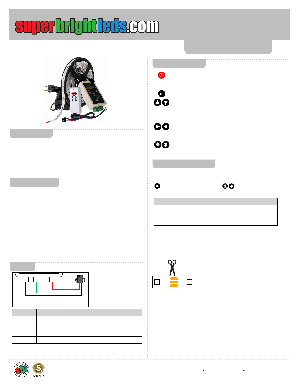
Included Parts
Controller Buttons
Setup and Installation
¹This setting is for the full 5 m strip, part number NDC2-RGB150. Increase
or decrease the pixel count by 1 for each additional 0.1 meter of strip.
Terminal Connection Wire Color for NDC2-RGB150
V- strip negative black
Data strip data green
CLK strip clock blue
V+ strip positive red
Setting Value
IC WS2811
LED Sequence RGB
Pixels¹ 50
ON/OFF button turns the controller on or o. The controller must
be o (powered on in standby mode) to adjust IC type, pixels,
and LED sequence.
Play/pause button can pause and then resume dynamic modes.
Mode increase/decrease buttons cycle up or down to the
next mode. They also adjust IC type, pixel number, and LED
sequence in the settings. M+ and M- perform the same function
on the remote control.
Speed up/down buttons increase or decrease speed during
dynamic modes. S+ and S- perform the same function on the
remote control.
Value selection buttons cycle through dierent setting types
(IC type, pixel number, and LED sequence) in standby mode.
WIFI-CON
Important: Read all instructions prior to installation. NDC2K-RGB150
4400 Earth City Expy, St. Louis, MO 63045 866-590-3533 superbrightleds.com
Rev Date: V2 02/03/2020
User Manual
V- V+
(Included LC4M-PT
connector)
D C
3 - Double-Sided Foam Pad (3M-FTP)
1 - Flathead Screwdriver (SDF-G2)
1 - LC4 Locking Connector to Pigtail (LC4M-PT)
1 - Controller (RGB-MDC83)
1 - Dream-Color RGB LED Light Strip (NDC2-RGB150)
1 - 12 VDC Power Supply (CPS-12V-60W)
+12V+12V
DINDIN
GNDGND


