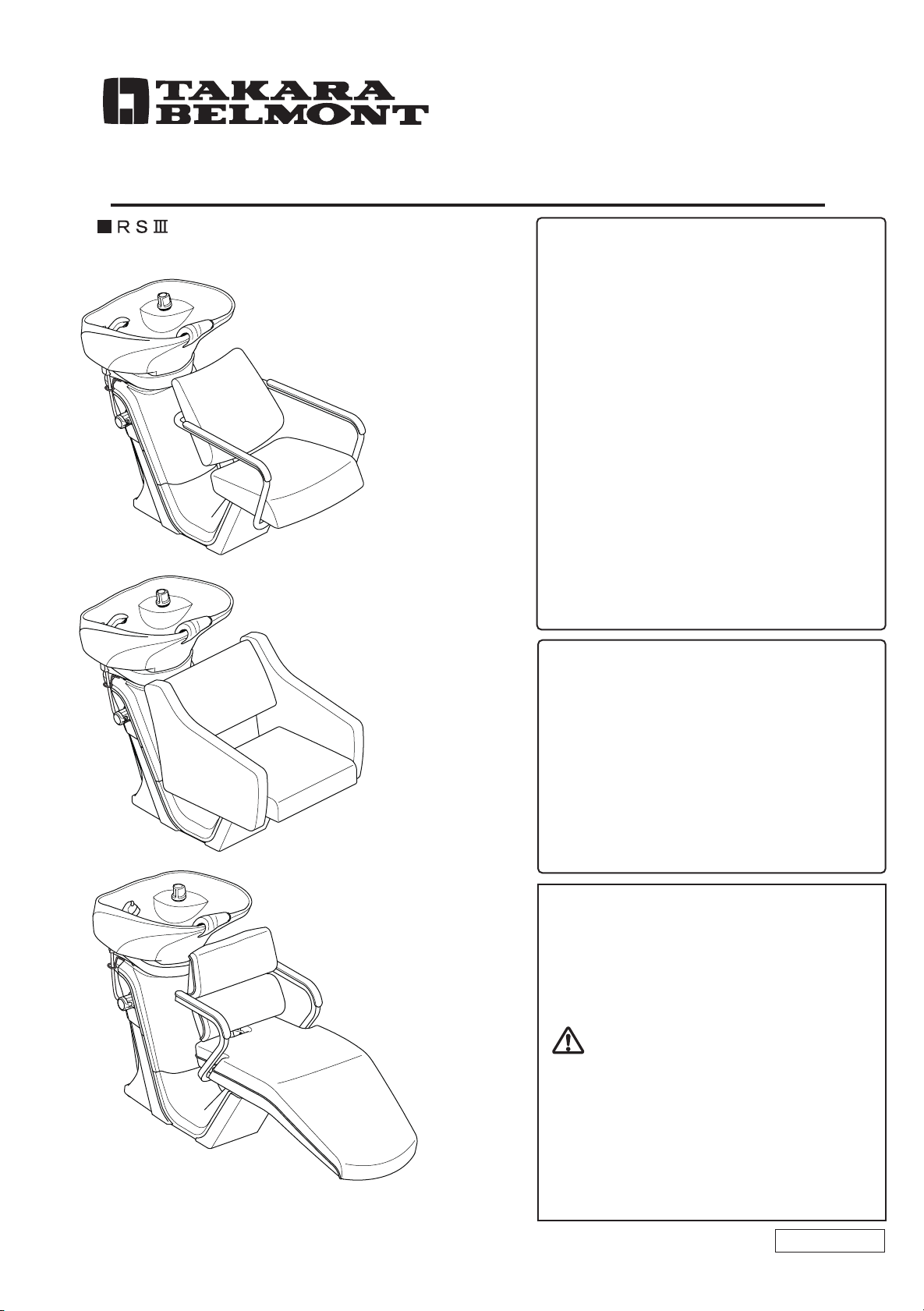
Takara Belmont RS III PRIME User manual
Other Takara Belmont Indoor Furnishing manuals

Takara Belmont
Takara Belmont CLIPPER AY-CLIP User manual

Takara Belmont
Takara Belmont Salon Console User manual

Takara Belmont
Takara Belmont Arcadia Series User manual

Takara Belmont
Takara Belmont EX-ESYMZ User manual

Takara Belmont
Takara Belmont DIVAN-Z AB-DVZF User manual

Takara Belmont
Takara Belmont Yume DX User guide

Takara Belmont
Takara Belmont AUBREY with MAJOLICA PORTO User manual

Takara Belmont
Takara Belmont Compact Hilox SP-PBN User manual

Takara Belmont
Takara Belmont LUAR User manual

Takara Belmont
Takara Belmont Square EPIPHANY User manual

Takara Belmont
Takara Belmont AK-S23S User manual

Takara Belmont
Takara Belmont LUAR AB-MF User manual

Takara Belmont
Takara Belmont BRAMU User manual

Takara Belmont
Takara Belmont LEGEND User manual

Takara Belmont
Takara Belmont ALVIS TETRA User manual

Takara Belmont
Takara Belmont BRAMU User manual

Takara Belmont
Takara Belmont Square EPIPHANY User manual

Takara Belmont
Takara Belmont Yume DX User manual

Takara Belmont
Takara Belmont apollo 2 User manual

Takara Belmont
Takara Belmont LEGEND AB-LGF User manual


Popular Indoor Furnishing manuals by other brands


Coaster
Coaster 4799N Assembly instructions

Stor-It-All
Stor-It-All WS39MP Assembly/installation instructions

Lexicon
Lexicon 194840161868 Assembly instruction

Next
Next AMELIA NEW 462947 Assembly instructions

impekk
impekk Manual II Assembly And Instructions

Elements
Elements Ember Nightstand CEB700NSE Assembly instructions