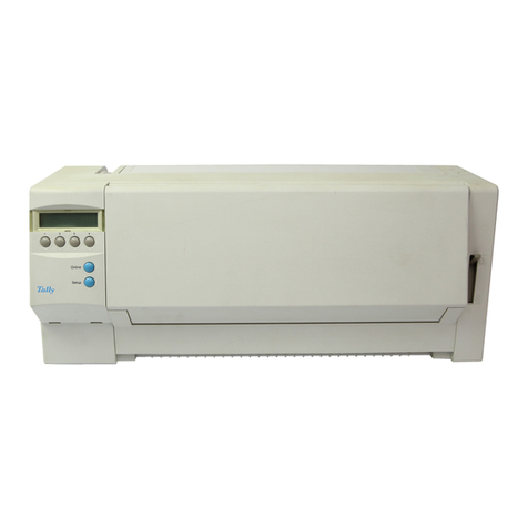
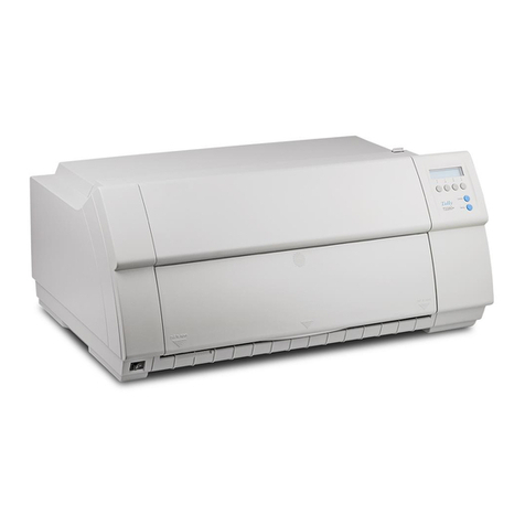
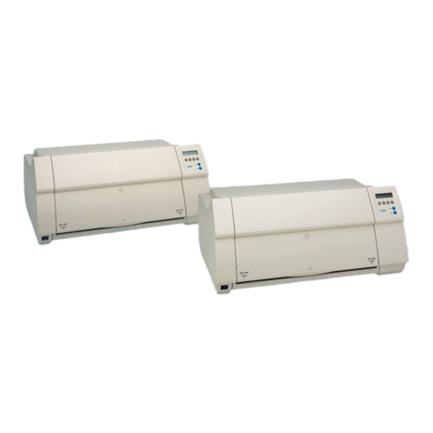
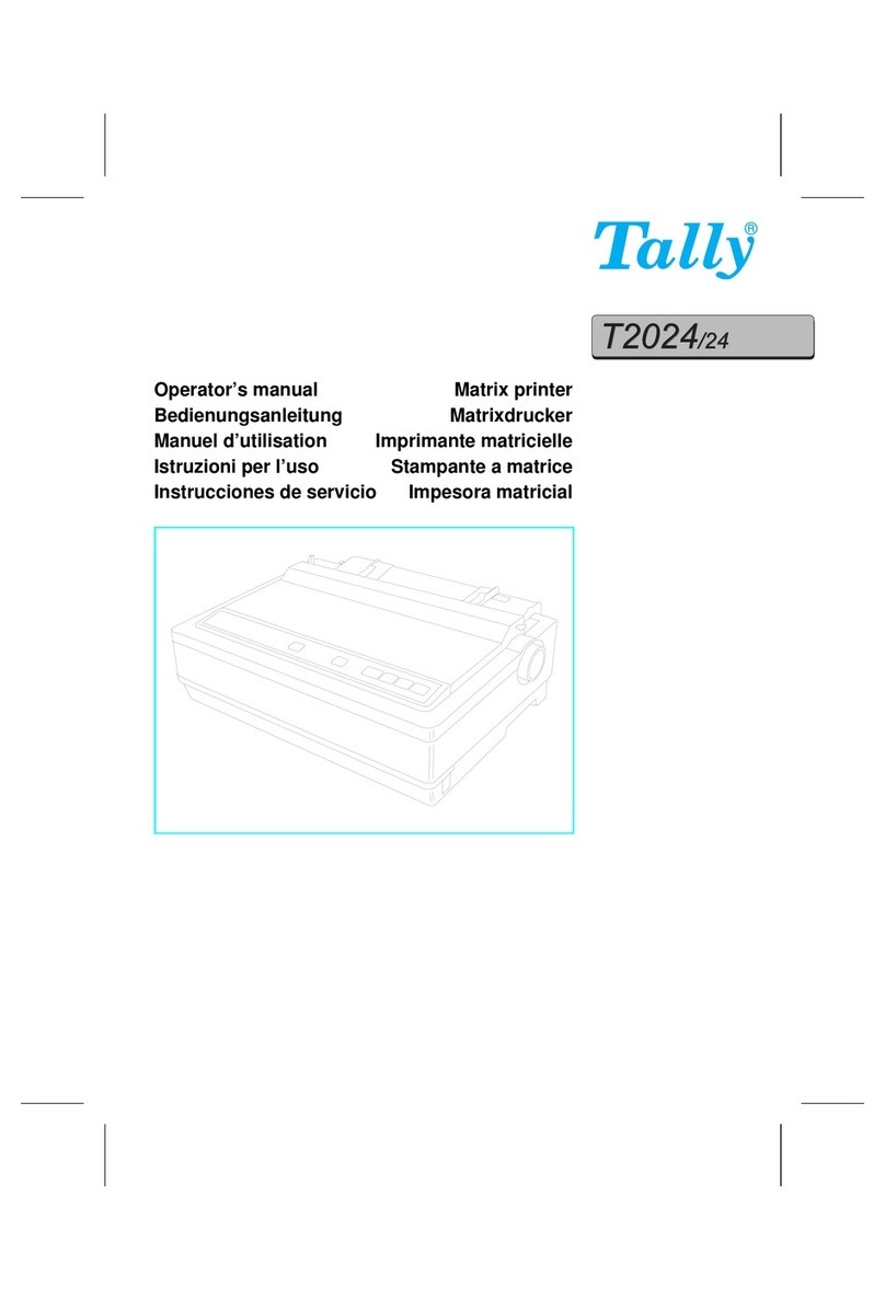
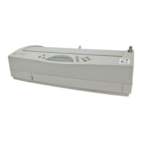
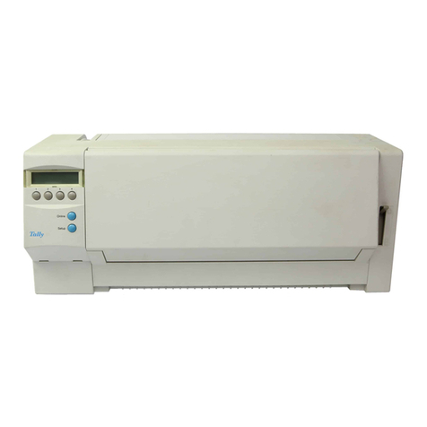
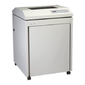
Tally T6215 User manual

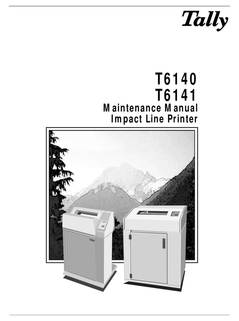
T6215
Maintenance Manual

P
R
I
N
T
E
D
O
N
R
E
C
Y
C
L
E
D
P
A
P
E
R
© May 2000
Tally Printer Corporation
All rights reserved
Printed in the United States
Manual Reference #083644
Tally Printer Corporation
8301 South 180th Street
Kent, Washington 98032
This Manual is published by Tally Printer Corporation for use with the computer printer described herein.
Translations, reprinting or copying by any means of this manual, complete or in part, in any different form
requires our explicit approval. Tally Printer Corporation reserves the right to revise this manual without notice,
for any reason. This includes, but is not limited to, utilization of advances in the state-of-the-art and changes
in the equipment or configuration thereof. Liability for difficulties arising from unknown or unforeseen
technical limitations is disclaimed.
FCC Statement
This equipment has been tested and found to comply with the limits for a Class A digital device, pursuant to
Part 15, Subpart B of the FCC Rules. These limits are designed to provide reasonable protection against harmful
interference when the equipment is operated in a commercial environment. This equipment generates, uses,
and can radiate radio frequency energy and, if not installed and used in accordance with the instruction manual,
may cause harmful interference to radio communications. Operation of this equipment in a residential area
is likely to cause harmful interfe rence, in which case the user will be required to correct the interference at
his own expense.

Table of Contents
Table of Contents


i
Table Of Contents
Table of Contents
Preface
About This Manual.................................................................................................................................. Pref–1
Chapter 1. Technical Overview ........................................................................................................ Pref–1
Chapter 2. Menu Operations ............................................................................................................ Pref–1
Chapter 3. Faults and Troubleshooting ............................................................................................. Pref–1
Chapter 4. Removing and Replacing Components ............................................................................ Pref–1
Appendix A. Schematics and Illustrated Parts Breakdowns ............................................................... Pref–1
Appendix B. Downloading Printer Firmware .................................................................................... Pref–1
Conventions ...................................................................................................................................... Pref–1
Chapter 1: Technical Overview
Technical Overview .................................................................................................................................... 1–1
T6215 Electronic Hardware Architecture..................................................................................................... 1–1
Engine Control Module ......................................................................................................................... 1–1
Control Processor ............................................................................................................................ 1–1
Sensor Inputs ................................................................................................................................... 1–1
Motor logic and drive ...................................................................................................................... 1–2
EEPROM ......................................................................................................................................... 1–2
Serial and Parallel Interfaces ................................................................................................................. 1–2
Serial ............................................................................................................................................... 1–2
Parallel ............................................................................................................................................ 1–2
Main Processor ..................................................................................................................................... 1–2
Motorola Cold Fire 5307 ................................................................................................................. 1–2
Altera EPM7064 .............................................................................................................................. 1–2
Table 1–1. Host Interface Configurations ........................................................................................ 1–2
Hammer Drive Module ......................................................................................................................... 1–3
Specifications .............................................................................................................................................. 1–3
Serial/Parallel Emulations ...................................................................................................................... 1–3
Font Styles ............................................................................................................................................. 1–3
Courier and Gothic ......................................................................................................................... 1–3
Data Processing and Draft ............................................................................................................... 1–3
OCR-A and OCR-B.......................................................................................................................... 1–3
Characters Per Inch ............................................................................................................................... 1–3
Table 1–2. Type Style, Character Matrix, Dot Density, and CPI Combinations ................................. 1–4
Lines Per Inch ....................................................................................................................................... 1–4
Dot Densities and Plot Speeds ............................................................................................................... 1–5
Table 1–3. Plot Data Output Speed................................................................................................. 1–5
Graphics Benchmarks ........................................................................................................................... 1–5
Table 1–4. AIAG Label Benchmark Results ..................................................................................... 1–5
Table 1–5. POSTNET Label Benchmark Results .............................................................................. 1–5
Paper Slew Speed .................................................................................................................................. 1–6

T6215 Maintenance Manual
ii
Table 1–6. Slew Speed.................................................................................................................... 1–6
Ribbons ................................................................................................................................................. 1–6
Forms/Paper Description ....................................................................................................................... 1–6
Acoustics .............................................................................................................................................. 1–6
Power Supply ........................................................................................................................................ 1–6
Table 1–7. Power Requirements ..................................................................................................... 1–6
Cooling System ..................................................................................................................................... 1–6
Safety .................................................................................................................................................... 1–7
Preventive Maintenance ........................................................................................................................ 1–7
Environment .......................................................................................................................................... 1–7
Operating ........................................................................................................................................ 1–7
Nonoperating .................................................................................................................................. 1–7
Heat Load Contribution ......................................................................................................................... 1–7
Table 1–8. Heat Load Contribution ................................................................................................. 1–7
Physical Configuration .......................................................................................................................... 1–8
Weight ............................................................................................................................................ 1–8
Printer Dimensions ................................................................................................................................ 1–8
Table 1–9. Printer Dimensions ........................................................................................................ 1–8
Industry and Agency Standards.............................................................................................................. 1–8
Electromagnetic Emissions .................................................................................................................... 1–8
Agency Approvals ................................................................................................................................. 1–8
Chapter 2: Menu Operations
Introduction ................................................................................................................................................ 2–1
Technical Access Mode ............................................................................................................................... 2–1
How To Enter Tech Access Mode........................................................................................................... 2–1
How to Exit Tech Access Mode ............................................................................................................. 2–1
Testing, Troubleshooting and Calibration ..................................................................................................... 2–1
Printer Tests ........................................................................................................................................... 2–1
Hex Dumps ........................................................................................................................................... 2–2
Printer Information Printouts and Displays ............................................................................................ 2–2
Help Menu ...................................................................................................................................... 2–2
Printing a HELP Menu In Tech Access Mode.............................................................................. 2–2
Report ............................................................................................................................................. 2–3
Report selections ....................................................................................................................... 2–3
Selecting a Printer Report .......................................................................................................... 2–3
TEST Menu.................................................................................................................................................. 2–4
Table 2–1 Test Menu....................................................................................................................... 2–4
Pattern Category .................................................................................................................................... 2–6
Print ................................................................................................................................................ 2–6
Print selections .......................................................................................................................... 2–6
Print2 .............................................................................................................................................. 2–6
Print2 selections ........................................................................................................................ 2–6
Plot ................................................................................................................................................. 2–7
Plot selections ........................................................................................................................... 2–7
Selecting And Running a Print Test ............................................................................................ 2–8

iii
Table Of Contents
Hammer .......................................................................................................................................... 2–8
Fault Override Category ........................................................................................................................ 2–8
Paper Motion .................................................................................................................................. 2–8
Paper Out........................................................................................................................................ 2–8
Ribbon Motion ................................................................................................................................ 2–9
Shuttle ............................................................................................................................................. 2–9
Temp ............................................................................................................................................... 2–9
Platen .............................................................................................................................................. 2–9
Control ............................................................................................................................................ 2–9
Link ................................................................................................................................................. 2–9
Sync ................................................................................................................................................ 2–9
Diagnostic Category .............................................................................................................................. 2–9
Calibrations ..................................................................................................................................... 2–9
Selecting And Running a Hammer Calibration Routine.............................................................. 2–9
Figure 2–1. Hammer Leadtime Calibration Printout Sample (partial) ............................................. 2–11
Selecting And Running a Platen Gap Calibration Routine ........................................................ 2–11
Meter ............................................................................................................................................ 2–12
Accessing the Meter Measurement Tests: ................................................................................. 2–12
Motors........................................................................................................................................... 2–13
Accessing the Motor Tests: ....................................................................................................... 2–13
Motor selections ...................................................................................................................... 2–13
Shuttle Speed ................................................................................................................................ 2–13
Shuttle Speed selections: ......................................................................................................... 2–13
Ribbon Speed ................................................................................................................................ 2–13
Speed selections: .................................................................................................................... 2–13
Ribbon Threshld ............................................................................................................................ 2–14
Threshold selections: ............................................................................................................... 2–14
Paper Out Thold............................................................................................................................ 2–14
Energy Star .................................................................................................................................... 2–14
Clear ............................................................................................................................................. 2–14
Clear selections ....................................................................................................................... 2–14
Shuttle Off ..................................................................................................................................... 2–14
Shuttle Change .............................................................................................................................. 2–14
Ribbon Ink, Dots per Pump ........................................................................................................... 2–14
Serial Dump .................................................................................................................................. 2–14
Control Panel Key Operations For Controlling Fault Reporting ............................................................ 2–15
ALL Fault Reporting ....................................................................................................................... 2–15
Four Faults Only............................................................................................................................ 2–15
Paper Out Only ............................................................................................................................. 2–15

T6215 Maintenance Manual
iv
Chapter 3: Faults and Troubleshooting
Faults .................................................................................................................................................... 3–1
Table 3–1. Display Messages .......................................................................................................... 3–3
The printer does not power up when switched on ............................................................................... 3–10
The Printer powers up but the Control Panel does not function. .......................................................... 3–11
The Control Panel Display functions partially, nonsensically, or not at all. .......................................... 3–11
There is no printed output but the printer appears to be operating normally. ....................................... 3–12
Printed output appears light ................................................................................................................ 3–12
Printed output appears shaky or fuzzy ................................................................................................. 3–13
Character columns not printing ........................................................................................................... 3–13
The Printer is out of paper — No Paper Out fault is reported ............................................................... 3–15
No Paper Motion — No Paper Motion fault is reported ....................................................................... 3–15
Table 3–2. Paper/Printing Corrective Action ................................................................................. 3–16
Figure 3–1. Power On Troubleshooting Sequence........................................................................ 3–18
Figure 3–1a. Power On Troubleshooting Sequence, Continued .................................................... 3–19
Figure 3–2. Print Data Troubleshooting Sequence ........................................................................ 3–20
Figure 3–2a. Print Data Troubleshooting Sequence, Continued .................................................... 3–21
Figure 3–2b. Print Data Troubleshooting Sequence, Continued .................................................... 3–22
Figure 3–2c. Print Data Troubleshooting Sequence, Continued .................................................... 3–23
Figure 3–2d. Print Data Troubleshooting Sequence, Continued .................................................... 3–24
Chapter 4: Removing and Replacing Components
Introduction ................................................................................................................................................ 4–1
Required Tools ...................................................................................................................................... 4–1
Service Procedures ...................................................................................................................................... 4–2
Procedure 1: Ribbon Platform Removal....................................................................................................... 4–3
Figure 1. Loosening screws on Ribbon Platform. ............................................................................ 4–3
Figure 2. Unplugging Ribbon Drive Motor cable. .......................................................................... 4–3
Procedure 2: Ribbon Motor Removal .............................................................................................. 4–4
Figure 3. Removing motor screws. ................................................................................................. 4–4
Figure 4. Unplugging Ribbon Motor cables. .................................................................................. 4–4
Procedure 3: Ribbon Motion Sensor PCA Removal...................................................................................... 4–5
Figure 5. Removing PCA screws. ................................................................................................... 4–5
Procedure 4: Control Panel Removal........................................................................................................... 4–6
Figure 6. Unplugging Control Panel cable. .................................................................................... 4–6
Procedure 4a: Control Panel Circuit Board removal ............................................................................. 4–7
Figure 7. Removing circuit board screws. ...................................................................................... 4–7
Procedure 5: Hammer Bank Removal.......................................................................................................... 4–8
Figure 8. Removing plastic cable cage. .......................................................................................... 4–8
Figure 9. Unplugging Hammer Bank ribbon cables........................................................................ 4–8
Figure 10. Removing screws on retainer clips. ............................................................................... 4–9
Figure 11. Removing nuts from underneath Hammer Bank. ........................................................... 4–9
Figure 12. Lifting Hammer Bank from printer............................................................................... 4–10
Figure 13. Replacing Shuttle Drive belt. .......................................................................................4–10
Procedure 6: Ribbon Shield Removal ........................................................................................................ 4–11
Figure 14. Removing the Ribbon Shield. ...................................................................................... 4–11

v
Table Of Contents
Procedure 7. 13-pack Hammer Replacement ........................................................................................... 4–12
Figure 15. Measuring old hammer for replacement size ............................................................... 4–12
Figure 16. Aligning the new hammer pack................................................................................... 4–13
Procedure 8: Coil Board Replacement...................................................................................................... 4–14
Figure 17. Coil board replacement. ............................................................................................. 4–14
Procedure 9: Shuttle Removal ................................................................................................................... 4–15
Figure 18. Removing Shuttle screws. ........................................................................................... 4–15
Figure 19. Removing screws from inside shuttle. ......................................................................... 4–15
Procedure 10: Platen Removal .................................................................................................................. 4–16
Figure 20. Location of circuit board. ............................................................................................ 4–16
Figure 21. Removing the Platen Springs. ...................................................................................... 4–17
Figure 22. Removing screws from the platen stop. ....................................................................... 4–18
Figure 23. Transferring components from old to new platen. ........................................................ 4–19
Figure 24. Adding grease. ............................................................................................................ 4–20
Procedure 11: Platen Gap Adjustment ...................................................................................................... 4–22
Figure 25. Platen Adjustment screws and use of shim. ................................................................. 4–23
Procedure 12: Print Mechanism Access (Tilting) ....................................................................................... 4–24
Figure 26. Unplugging the Power Supply cable. .......................................................................... 4–24
Figure 27. Print Mechanism tilted and held by strut. .................................................................... 4–25
Procedure 13: Distribution PCA Removal ................................................................................................. 4–26
Figure 28. Removing screws on mounting bracket. ...................................................................... 4–26
Procedure 14: Lower Tractor Removal ...................................................................................................... 4–27
Figure 29. Location of Paper Out sensor cables. .......................................................................... 4–27
Figure 30. Removing Retaining (Snap) rings. ................................................................................ 4–27
Figure 31. Ground spring. ............................................................................................................. 4–28
Figure 32. Round and square shafts. ............................................................................................. 4–28
Procedure 15: Upper Tractor Removal ..................................................................................................... 4–30
Procedure 16: Tractor Phasing/Paper Drive Belt Tension Adjustment ........................................................ 4–31
Figure 33. Tractor phasing and paper drive belt. .......................................................................... 4–31
Figure 34. Paper Tension Lever in middle position. ...................................................................... 4–32
Figure 35. Placing the Phasing Gauge .......................................................................................... 4–32
Figure 36. Placing Tension Gauge ................................................................................................ 4–33
Figure 37. Placing Paper Tension Gauge. ..................................................................................... 4–34
Procedure 17: Paper Drive Motor Removal .............................................................................................. 4–35
Figure 38. Paper Drive Motor location. ........................................................................................ 4–35
Procedure 18: Shuttle Motor Removal ...................................................................................................... 4–36
Figure 39. Shuttle Motor .............................................................................................................. 4–36
Procedure 19: Control PCA Assembly Removal ........................................................................................ 4–37
Figure 40. Front of Control PCA assembly after cover has been removed. .................................... 4–37
Procedure 20: Power Supply Assembly Removal...................................................................................... 4–38
Figure 41. Power Supply Assembly. ............................................................................................. 4–38

T6215 Maintenance Manual
vi
Appendix A: Illustrated Parts Breakdowns and Schematics
Illustrated Parts Breakdowns and Schematics .............................................................................................. A–1
Appendix B:
Firmware Update Procedure ....................................................................................................................... B–1

Preface
Preface


Pref–1
Preface
About This Manual
This manual presents maintenance, alignment, and troubleshooting procedures for the
T6215 printer. Also included are all schematics and diagrams necessary for repair and
maintenance. The following chapter and appendix summaries will provide you with a
survey of the manual contents.
Chapter 1. Technical Overview
In Chapter 1, you will find detailed descriptions of the technical aspects of your printer.
In addition, design and operational specifications are discussed.
Chapter 2. Menu Operations
In Chapter 2, you will find the Menu Operations concerned with troubleshooting and
maintaining your printer.
Chapter 3. Faults and Troubleshooting
This chapter contains a listing of the error and fault messages that may appear on the
Control Panel Display and various troubleshooting procedures and problem fixes.
Chapter 4. Removing and Replacing Components
This chapter presents instructions for removing and replacing/reinstalling various printer
components.
Appendix A. Schematics and Illustrated Parts Breakdowns
In appendix A schematics are given to assist you in troubleshooting problems and
locating components that control your printer operations. Also included are exploded
views of all printer components along with detailed parts listings.
Appendix B. Downloading Printer Firmware
In this appendix, instructions are given on downloading firmware for your printer.
Conventions
We use the following conventions throughout this manual.
Notes may be considered as supplementary information.
This symbol marks information about actions that may damage the equipment
or injure the user.
These statements list special instructions, warnings, or reminders about printer
operations.

T6215 Maintenance Manual
Pref–2
Blank
Page

Chapter 1
Chapter 1:
Technical Overview


1–1
Chapter 1. Technical Overview
Technical Overview
The T6215 is a high speed, low cost, line impact dot matrix printer. It's maximum
print speed is 1500 lines per minute in uppercase draft text mode. It prints many
fonts in a number of languages, and plots raster graphics and images at a wide
variety of dot densities. The T6215 comes standard with Serial and Parallel inter-
faces and supports other interfaces through the use of user-installable PSIO inter-
face cards. OEM add-in cards are supported via an internal IEEE 1284 connector.
The T6215 does not accept the T6090/T6180 "Personality Module" cards.
T6215 Electronic Hardware Architecture
The electronic design of the T6215 is implemented in two basic modules: the
Engine Control Module and the Hammer Driver Module.
Engine Control Module
The primary components of the Engine Control Module are:
•Main Processor - Motorola Cold Fire®5307
•Flash Memory - 2 M-bytes
•SDRAM - 2 M-bytes
•EPLD - Altera EPM 7064
•Interface - specific devices
•Control Processor –Intel 87C196KC
•Sensor Inputs
•Motor logic and drive
•EEPROM –24C64
Control Processor
•20 MHz clock
•High speed outputs for driving the paper motor and hammer firing
•High speed inputs for synchronizing timing of the shuttle position
•8 channel 10 bit Analog to Digital Converter for sensor readings (paper
out, paper motion, shuttle motion, ribbon motion, platen gap, hammer
current, power supply voltage, ambient temperature)
•Serial channel for communication (19.2K bps) with Main CPU
•Port control of Shuttle and Ribbon microcontroller
•Port control of control panel, and hammer loading
Sensor Inputs
•Paper motion –optical
•Paper out –optical
•Platen gap –Hall-effect
•Shuttle motion –optical
•Ambient temperature –thermistor
•Power supply voltage –resistor divider
•Ribbon motion - optical
•Ribbon weld detect - optical

T6215 Maintenance Manual
1–2
Motor logic and drive
•8 Hz bridge Motor drive chips (2 for ribbon, 2 for shuttle, 2 for paper,
and 2 for ribbon ink pump) –Allegro 3952
EEPROM
The EEPROM stores engine calibration and printer configuration settings.
Serial and Parallel Interfaces
Serial
•MC145407 (5V) chip is used for the RS-232 drivers and receivers
•Both DTR/Busy and XON/XOFF is supported
•Standard secondary RTS on pins 11 and 19. Primary RTS is capable of
being jumpered to pin 4
Parallel
•Altera EPM7064 and 74LS374/74LCX244 –supports IEEE-1284 compat-
ibility and nibble modes
Main Processor
Motorola Cold Fire 5307
•56MHz clock
•32-bit CPU bus
•Two direct Memory Access (DMA) channels –One for hammer loading,
and one for the IEEE-1284 parallel Interface
•Two serial channels –One for the control of CPU communication, and
one for the external serial interface
•Internal SDRAM controller
Altera EPM7064
•Logic for IEEE-1284 Parallel interface
•Logic for PSIO Interface
The following table shows host interface configuration options
Table 1–1. Host Interface Configurations
Personality Module Standard Ser/Par LANPlex FourPlex
Host I/Os IEEE 1284 IEEE 1284 IEEE 1284
RS-232-C RS-232-C RS-232-C
Ethernet Twinax
Coax
Optional Configurations IPDS IPDS

1–3
Chapter 1. Technical Overview
Hammer Drive Module
•resident on shuttle/hammer assembly
•hammer drive ASICs
•hammer drive transistors
•cold drive energy damping diodes
Specifications
Serial/Parallel Emulations
Nine emulations are available on the T6215: MT660, Genicom ANSI, HP2564C,
Printronix P600, Printronix P6000, IBM Proprinter III XL, Epson FX-100+, DEC
LG01, and MTPL.
Font Styles
There are 6 resident type styles available on your printer. They include: Courier,
Data Processing, Draft, Gothic, OCR-A, and OCR-B. All font styles and the two
output modes (Enhanced and Constant Density Fonts for Draft and DP) are se-
lected through the printer control panel.
Courier and Gothic
These two font styles provide near letter quality (NLQ) printing on your printer.
They print at higher dot densities and use denser character matrixes. NLQ type
styles provide greater readability for reports and other text output.
Data Processing and Draft
Data Processing and Draft styles appear in two modes: Constant Density (CDF)
and Enhanced. Constant Density Fonts print at the same dot density regardless of
the CPI. This produces consistent print speed even when changing from one CPI
to another.
Enhanced Mode provides higher resolution and a greater range of CPI’s than CDF
Mode. Because Enhanced Mode uses a variety of dot densities, you should expect
a change in print speed of text when switching from one CPI to another.
OCR-A and OCR-B
These font styles print at 10 CPI only. They are used mainly for Optical Character
Recognition.
Characters Per Inch
The T6215 offers a variety of CPIs for use in printer output, which are dictated by
the font style selected. Each CPI is based on one of twelve character matrixes and
twelve dot densities. Each matrix uses a specific number of dot columns for
character composition and intercharacter gap. CPIs are grouped in any given type
style by the base CPI matrix used for the group. These base CPIs are 10, 12, and
15.

T6215 Maintenance Manual
1–4
Table 1–2. Type Style, Character Matrix, Dot Density, and CPI Combinations
Print Modes Type Styles 10 CPI Group 12 CPI Group 15 CPI Group
Constant Density Draft Base Matrix: 9 x 8 Base Matrix: 7 x 8 Base Matrix: 5 x 8
Dot Density: 60 x 48 Dot Density: 60 x 48 Dot Density: 60 x 48
CPIs: 5 and 10 CPIs: 6, 6.67, 12, CPIs: 15 & 17.14
& 13.33
Data Processing Base Matrix: 9 x 12 Base Matrix: 7 x 12 Base Matrix: 5 x 12
Dot Density: 60 x 72 Dot Density: 60 x 72 Dot Density: 60 x 72
CPIs: 5 & 10 CPIs: 12 & 13.33 CPIs: 15 & 17.14
Enhanced Draft Base Matrix: 9 x 8 Base Matrix: 13 x 8 Base Matrix: 9 x 8
Dot Density: 60 x 48 Dot Density: 80 x 48 Dot Density: 120 x 48
CPIs: 5 &10 CPIs: 6, 6.67, 12, CPIs: 7.5, 8.33, 8.57,
& 13.33 15, 16.67, 17.14, & 20
Data Processing Base Matrix: 9 x 12 Base Matrix: 13 x 12 Base Matrix: 9 x 12
Dot Density: 60 x 72 Dot Density: 80 x 72 Dot Density: 120 x 72
CPIs: 5 & 10 CPIs: 6, 6.67, 12, CPIs: 7.5, 8.33, 8.57,
& 13.33 15, 16.67, 17.14, & 20
Near Letter Gothic Base Matrix: 17 x 16 Base Matrix: 13 x 16 Base Matrix: 9 x 16
Quality Dot Density: 90 x 96 Dot Density: 90 x 96 Dot Density: 120 x 96
CPIs: 5 &10 CPIs: 6, 6.67, 12, CPIs: 7.5, 8.33, 8.57,
& 13.33 15, 16.67, 17.14, & 20
Courier Base Matrix: 17 x 16 Base Matrix: 13 x 16 Base Matrix: 9 x 16
Dot Density: 90 x 96 Dot Density: 90 x 96 Dot Density: 120 x 96
CPIs: 5 & 10 CPIs: 6, 6.67, 12, CPIs: 7.5, 8.33, 8.57,
& 13.33 15, 16.67, 17.14, & 20
Optical Character OCR-A Base Matrix: 9 x 16
Recognition Dot Density: 60 x 96
CPIs: 10
OCR-B Base Matrix: 17 x 24
Dot Density: 90 x 144
CPIs: 10
Lines Per Inch
Ten lines per inch (LPI) settings are available through the control panel. They include
1.5, 2, 3, 4, 5, 6, 8, 9, 10, and 12 LPI. In some emulations the availability of certain
LPI’s are restricted.
Other manuals for T6215
1
Table of contents
Other Tally Printer manuals

Tally
Tally T6215 User manual

Tally
Tally T8006 User manual

Tally
Tally T9014 User manual

Tally
Tally XPRESS T9412i Installation instructions

Tally
Tally T3016 User manual

Tally
Tally T2033S User manual

Tally
Tally T2280 SprintPro User manual

Tally
Tally T2150 SprintPro User manual

Tally
Tally T7070 User manual

Tally
Tally t2145 User manual

Tally
Tally T9412 User manual

Tally
Tally T9114 Installation guide

Tally
Tally T2030/24 User manual

Tally
Tally T6218 Configuration guide

Tally
Tally XPRESS T9412i User manual

Tally
Tally T2265 SprintPro User manual

Tally
Tally Xpress T8016 User manual

Tally
Tally T9408 User manual

Tally
Tally T9006 User manual

Tally
Tally T2040 User manual