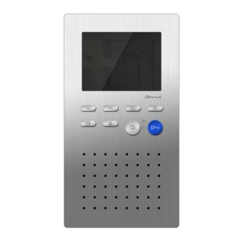
TCS IMM2300 User manual

TCS TürControlSysteme AG Subject to technical changes.
Mail: info@tcsag.de PI_IMM2300_Art0031160-uk.doc
Product information
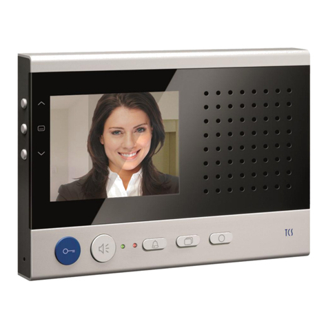
Video indoor station for
hands-free talking
IMM2300

2 09/2011
TCS TürControlSysteme AG Subject to technical changes.
Mail: info@tcsag.de PI_IMM2300_Art0031160-uk.doc
Table of contents
Scope of delivery .................................................................................................................3
Safety instructions................................................................................................................3
General on the conduit in TCS video systems.....................................................................3
Term.................................................................................................................................3
6-wire operation................................................................................................................3
Principle loop resistance...............................................................................................4
Measurement loop resistance.......................................................................................4
Device overview...................................................................................................................5
Technical data .....................................................................................................................5
Display and control elements...............................................................................................6
Application...........................................................................................................................7
Brief description...................................................................................................................7
Basic module....................................................................................................................7
Video module ...................................................................................................................7
Mounting and installation.....................................................................................................8
Installing the lower cover..................................................................................................8
Without flush-mounted socket ......................................................................................8
Connection of cables........................................................................................................9
Connect the device.......................................................................................................9
Connect the video module............................................................................................9
Terminating resistor......................................................................................................9
Snapping-on the upper cover of the modules.................................................................10
Open the device.............................................................................................................10
Note on power supply.....................................................................................................11
Wiring example...............................................................................................................11
Connection diagram.......................................................................................................11
Commissioning ..................................................................................................................12
Settings..............................................................................................................................12
Factory settings..............................................................................................................12
Preset times................................................................................................................12
AS address-dependent image activation........................................................................12
Volume internal communication .....................................................................................13
Programming the basic modules .......................................................................................13
Manually programming...................................................................................................13
Programming with the Service Device TCSK-01............................................................16
Operation...........................................................................................................................17
Ring tone selection.........................................................................................................17
FAQ ...................................................................................................................................18
Cleaning.............................................................................................................................20
Service...............................................................................................................................20

09/2011 3
TCS TürControlSysteme AG Subject to technical modifications.
Mail: info@tcsag.de PI_IMM2300_Art0031160-uk.doc
Scope of delivery
1 x indoor station IMM2300
(lower cover, upper cover of basic module, lower cover of video module)
1 x pluggable screw terminal for connecting the video modules
product information
instruction manual
Safety instructions
!
Mounting, installation and commissioning have to be carried out only by qualified elec-
tricians!
When working in systems with 230 V mains voltage, the safety requirements according to
DIN VDE 0100 must be observed.
When installing TCS:BUS systems, the general safety regulations for telecommunication
systems according to VDE 0800 must be observed:
separated cabling for heavy and low current lines,
minimum distance of 10 cm for common cablings,
use of separators between heavy and low current lines in shared cable ducts,
use of standard telecommunication lines, e.g. J-Y (St) Y with 0.8 mm diameter,
existing lines (modernisation) with deviating cross sections can be used in compliance
of the loop resistance.
!
With suitable requirements to protect against lightning, it has to be ensured that a vol-
tage of each 32 V DC is not exceeded at the TCS:BUS wires a and b.
General information on the cable routing in TCS video systems
Term
6-wire operation
Standard operating mode. Video operation in which two separated
masses (b and M) are used.
6-wire operation
The cable routing is determined by the given structural conditions and is only limited by the
length.

4 09/2011
TCS TürControlSysteme AG Subject to technical changes.
Mail: info@tcsag.de PI_IMM2300_Art0031160-uk.doc
When choosing the cable length observe: the loop resistance a-b and M-P should not
exceed the maximum of 8 Ω(table 1).
If the loop resistance exceeds 8 Ω: plan multiple wiring of the lines (double twisted
strands).
Optional strand or star formed wiring.
Do not use more than 6 video indoor stations per strand. For systems with more video
indoor stations plan the use of video distributors (FVY1200, FVY1400).
Up to 64 front-door stations (16 of them with video) and almost an unlimited number of
indoor stations can be connected polarity-free (a/b) within one system (polarity-free only
in 6-wire operation). For this, a suitable power supply and control unit has to be used.
Table 1: loop resistances
cable length a-b/ M-P
in m
cable diameter
0.6 mm
0.8 mm
loop resistance in Ω
10
1.22
0.69
20
2.45
1.38
30
3.67
2.07
40
4.90
2.76
50
6.12
3.44
60
7.35
4.13
70
4.82
80
5.51
90
6.20
100
6.89
Principle loop resistance
Measurement loop resistance
Rule:
None of the devices (AS, IS or FE) should each be
further than 8 Ohm away from the power supply
control unit (VS).
Rule:
Switch off 230 V / 50 Hz of the VS.
Install a-b short-circuit at the VS.
All other devices do not disturb the measurement
and can stay connected.
8 Ohm:
around 65 m distance AS-VS by 0.6 mm diameter
around 115 m distance AS-VS by 0.8 mm diameter
short-circuit a, b
here

09/2011 5
TCS TürControlSysteme AG Subject to technical modifications.
Mail: info@tcsag.de PI_IMM2300_Art0031160-uk.doc
Device overview
Technical data
supply voltage: +24 V ±8 % (power supply and control unit)
housing: plastics, (colors like in price list)
housing dimensions: H 146 mm x W 172 mm x D 27 mm
mounting dimensions: H 148 mm x W 172 mm x D 29 mm
weight 300 g
acceptable ambient temperature: 0 °C to 40 °C
degree of protection: IP 40
input current standby (3-wire operation): I(a) = 0.5 mA, I(P) = 4.7 mA
max. input current: I(Pmax) = 155 mA
video module TFT-color module
screen diagonal 2.4 inch
resolution 480 x 234 pixel
video signal entrance symmetrical 1 Vss FBAS
Only video 6-wire technique possible!
display call OFF (red)
display additiona
functions (green)
door release
button
function key
light switch button
call OFF button
ring tone volume control
loudspeaker
display
basic module
video module
microphone
speech button
4 control keys
left / right /
up / down
image switch
button
brightness control
color brilliance control

6 09/2011
TCS TürControlSysteme AG Subject to technical changes.
Mail: info@tcsag.de PI_IMM2300_Art0031160-uk.doc
Display and control elements
display call OFF (red)
call OFF activated (LED is ON) or
display of busy speech channel (LED blinks)
display additional functions
(green)
door call, incoming internal call, speaking active
door release automatic or call diversion, if activated
speech button
call acceptance, activate speaking,
simplex communication
end communication
ring tone selection (door call front-door station 2, AS >
AS threshold*)
door release button
open the door (= WE**)
end communication
ring tone selection (door call front-door station 1, AS ≤
AS threshold)
trigger light switch function***
function key
in the basic module
control function 8 (= WE)
internal call (to the indoor station)
door release automatic
call diversion
ring tone selection internal call (call from the indoor sta-
tion)
light switch button
switching lights
ring tone selection floor call (call from the flat door)
call OFF button
ring tone OFF button
end communication
initiating and ending the programming and ring tone
selection
ring tone volume control
ring tone volume continuously adjustable
image switch button
in the video module
to switch on the image resp.
to switch between different cameras
4 control keys
in the video module
to swivel and incline a PTZ camera
(left, right, up, down)
brightness control
continuously adjustable
contrast/color intensity control
continuously adjustable
* Factory setting: AS threshold = 0, limit of the AS address areas can be adjusted with the device configurator
configo™ or set ex works on requirement.
** WE = factory setting
*** if the light switch function in the front-door station is activated

09/2011 7
TCS TürControlSysteme AG Subject to technical modifications.
Mail: info@tcsag.de PI_IMM2300_Art0031160-uk.doc
Application
Manually controlled simplex communication can be activated.
The IMM 2300 is an indoor station for hands-free talking, manually controlled simplex
communication can be activated
It is designed for surface-mounting.
It is suitable for the operation in TCS video systems and combined audio/video systems.
Brief description
Basic module
speech button: for call acceptance and switching over speaking / hearing
light switch button
blue door release button with floor door release function (can be activated)
speech button: for call acceptance and reversing key speaking / hearing
function key (ex works: with control function) with alternative allocation (can be acti-
vated): internal call, door release automatic, call diversion
ring tones can be adjusted by the resident, choice of 13 ring tones
acoustic call distinction between 2 doors, flat door and internal call
ring tone volume can be adjusted manually, volume for internal communication adjusta-
ble
ring tone mute with optical display
optical display of door calls
optical display of a busy line when communication is established
automatic hands-free talking after internal call can be activated
one parallel call can be activated
sending of the sender serial number in case of internal calls can be (de-) activated,
source indication e.g. at IMM1100 or IMM2100 possible (with configuration software
configoTM)
unlimited communication time can be switched ON/OFF (with configuration software
configoTM)
(but limited by other indoor or front-door station, that is realising the voice communica-
tion)
audio privacy function and automatic call cut-OFF
Video module
video surveillance: image switch button to switch on the image resp. for switching be-
tween different cameras
AS dependent video image activation
4 control keys (right, left, up, down)
brightness, color saturation / manually adjustable
integrated two-wire video receiver for direct connection to TCS video systems

8 09/2011
TCS TürControlSysteme AG Subject to technical changes.
Mail: info@tcsag.de PI_IMM2300_Art0031160-uk.doc
Mounting and installation
!
Attention!
The video indoor stations have to be (de-)installed voltage-free only!
Installing the lower cover
Without flush-mounted socket
Install the lower cover at the at-
tachement holes with suitable
screws on the wall (as shown in
the illustration).
lower cover
With flush-mounted socket
Position the flush-mounted sock-
et behind the cable gland.
Install the lower cover at the at-
tachement holes with suitable
screws on the wall (as shown in
the illustration).
position
flush-
mounted
socket

09/2011 9
TCS TürControlSysteme AG Subject to technical modifications.
Mail: info@tcsag.de PI_IMM2300_Art0031160-uk.doc
Connecting the lines
Cut the wires for the basic and video
module in different lengths (see illustra-
tion to the right).
Minimize the length of the lines above
the lower cover to place the lines without
any problems and do not clamp the lines
when snapping-on the upper cover.
Connecting the device
Connect the lines according to the label-
ling.
Connecting the video module
Connect the prepared video lines to the
pluggable screw terminals (in the acces-
sories) and plug them to the tripled pin
header (see illustration) at the printed
circuit board of the video module.
Pay attention that V1 and V2 are con-
nected correctly!
Make sure that the plug-terminal is
plugged in accordance to the illustration!
Terminating resistor
Remove the terminating resistor if the
device is not installed at the end of a
TCS:BUS video strand.
pluggable
screw
terminal
terminating
resistor

10 09/2011
TCS TürControlSysteme AG Subject to technical changes.
Mail: info@tcsag.de PI_IMM2300_Art0031160-uk.doc
Snapping-on the upper covers of the modules
Put on the upper cover on both locking
brackets at the lower cover (1).
Lock the upper cover in place (2).
Opening the device
1. There are rectangular release
openings at the underside of
the device for every module.
Insert a screwdriver (around 7
mm) with slight pressure
straight into this opening.
2. The upper covers can be re-
moved at the underside.
3. Lift the upper cover of both
upper locking brackets.

09/2011 11
TCS TürControlSysteme AG Subject to technical modifications.
Mail: info@tcsag.de PI_IMM2300_Art0031160-uk.doc
Notice on the power supply
!
In case of power supply with BVS20 or BVS100 additionally use NGV1011!
Wiring example
Connection diagram
J1 must be plugged, if the
device is installed at the
end of a TCS:BUS video
strand.
Remove J1, if the device
is not installed at the end
of a TCS:BUS video
strand.

12 09/2011
TCS TürControlSysteme AG Subject to technical changes.
Mail: info@tcsag.de PI_IMM2300_Art0031160-uk.doc
Commissioning
!
First, completely install the system, then connect it to voltage !
V1 and V2 must not be connected with P-, a- or b-wire.
When connecting the video wires V1 (+) and V2 (-) the polarity has to be observed.
In case of a distorted image after the commissioning, switch off the device and
change the wires for the video signal.
Settings
Presets ex works
The video indoor station is equipped with an EEPROM, in which the following device set-
tings are stored.
Preset times
communication time
max. 2 min
image switch time
80 sec
flashing period of the red LED, if
„video-/speech channel is busy“ when
pressing the speech or image button
3 sec
6 x flashing
internal standby time
around 2 min, if the device was called
around 30 sec, if the device is calling and
waiting for call acceptance
AS-address dependent image activation
If there are not only video front-door stations but also front-door stations without camera
within one system, the image is not activated, when a call arrives from these front-door
stations.
In order to guarantee this function, all possible AS-addresses are separated into two
areas:
AS-address 0 –31*
reserved for video front-door sta-
tions
image is activated in case of
a door call
AS-address from 32
free, for front-door stations without
camera
image is not activated in
case of a door call
* The limit of the AS-address areas can be adjusted ex works if required.
Note:
The AS-addresses of the front-door stations should be allocated via Service Device.
For more information see service information within the TCS Installer 5 / 4 (version 1) or TCS Installer 7 / 4 (version 2).

09/2011 13
TCS TürControlSysteme AG Subject to technical modifications.
Mail: info@tcsag.de PI_IMM2300_Art0031160-uk.doc
volume internal
communication
Turn the volume control clockwise to in-
crease the volume.
Programming the basic module
Manual programming
Legend for programming
The programming takes always place in four steps:
1
2
3
4
Initiate the programming
Preselection
Final selection
End the programming
1
Initiate the programming
press call OFF button (8 sec), until release
a short acknowledgement tone sounds

14 09/2011
TCS TürControlSysteme AG Subject to technical changes.
Mail: info@tcsag.de PI_IMM2300_Art0031160-uk.doc
Programming
function
2
Preselection
3
Final selection
press button (8 sec) until a short acknowled-
gement tone sounds and the green LED
blinks,
release button
press button short,
short acknowledgement tone
sounds and green LED goes out
door release automatic
call diversion
Note:
Before programming
the call diversion, the
AS-address of the front-
door station is to be set
and blocked with the
Service Device.
to be executed at the destined indoor
station: press speech button / lift handset
or
internal call
(at function key)
to be executed at the destined indoor
station: press speech button / lift handset
or
control function 8
(at function key)
switch on automatic
hands-free talking after
internal call (if switched
off) or switch off (if
switched on)

09/2011 15
TCS TürControlSysteme AG Subject to technical modifications.
Mail: info@tcsag.de PI_IMM2300_Art0031160-uk.doc
switch on floor door
function (if switched off)
or switch off (if switched
on)
Programming
function
2
Preselection
3
Final selection
switch on parallel call
Note:
Deactivate the function
with programming func-
tion reload factory set-
ting.
to be executed at the destined indoor
station 1: press speech button / lift handset
or
switch off parallel call
block ring tone
selection
block manual
programming
lift pogramming lock
Attention!
First switch on the
BVS programming
mode of the system.
Carry out the steps 1
to 4.
Switch off program-
ming mode of the
system.
reload factory settings
press door release button for 8 sec

16 09/2011
TCS TürControlSysteme AG Subject to technical changes.
Mail: info@tcsag.de PI_IMM2300_Art0031160-uk.doc
4
End the programming
Press call OFF button short or automatically, if no button is pressed for more than 8 sec.
Programming with the Service Device TCSK-01
For further information see TCS Installer, 7 Service Device TCSK-01 or programming
handbook TCSK-01.
searching telephones
parallel call
ParS No
Ser No

09/2011 17
TCS TürControlSysteme AG Subject to technical modifications.
Mail: info@tcsag.de PI_IMM2300_Art0031160-uk.doc
Operation
Ring tone selection
In total, for 4 different incoming calls (door calls from 2 front-door stations, floor call, inter-
nal call) different ring tones can be adjusted.
1
End voice communication: press call OFF button for around 8 sec.
With the output of a signal tone the ring tone selection is activated.
By pressing the following buttons a ring tone can be selected. You can chose be-
tween 13 tones: 7 alpha tones, 6 gong tones.
2a
select ring tone from
the front-door station*
Press door release button until the desired ring tone
sounds. The ring tone selected last will be stored.
2b
select ring tone from
second front-door sta-
tion (if existing)
Then press the speech button until the desired ring tone
sounds. The ring tone selected last will be stored.
2c
select ring tone from
floor door
Press the light switch button until the desired ring tone
sounds. The ring tone selected last will be stored.
2d
select internal ring to-
ne
Press the function key until the desired ring tone sounds.
The ring tone selected last will be stored.
3
Press call OFF button shortly.
If no button is pressed for more than 8 sec, the device automatically terminates the
adjustment mode for ring tones. With the output of a signal tone, the ring tone se-
lection is deactivated.
* When first adjusting the ring tone, also the second front-door station is fitted with the same ring tone as the first one. If
the ring tone is adjusted separately (2b) for the second front-door station, it always has to be set independently.

18 09/2011
TCS TürControlSysteme AG Subject to technical changes.
Mail: info@tcsag.de PI_IMM2300_Art0031160-uk.doc
FAQ
Error pattern
Possible causes
Our suggested solution
The video image is black and
white.
The color saturation control of the
indoor station is set to minimum.
Adjust the contrast resp. color
saturation control.
The transmission level of the video
BUS is too low.
The transmission level can be
readjusted at many components of
the video BUS (e.g. FVY).
Please check it in the product
information of the active transmis-
sion components.
The light intensity of at least 10 lux
is not reached. Thus the camera
switches to black/white.
The camera modules of the front-
door stations are very photosensi-
tive. Please ensure a sufficient
illumination or use external cam-
eras.
The colors at the video monitor
of the indoor station are too
bright or the image in total is
too bright.
The color saturation control at the
station is set too high.
Turn down the color saturation
control.
The brightness control of the station
is set too high.
Turn down the brightness control
at the station.
The level of the video signal is too
high.
Turn down the level of the video
BUS (e.g. rotary switch at the
board of the camera). Is only
working, if the terminating resis-
tance at the station or active ex-
tended functions (e.g. FVY) is set
correctly.
The terminating resistor at the end
of the strand is not plugged.
Please plug the terminating resis-
tor.
Colors on the monitor are
without contrast.
The video signal level is not suffi-
ciently high enough.
The connection lines of a surface-
mounted camera were extended
incorrectly.
The line length between two active
video components was impermiss-
ibly exceeded.
Level reduction can be compen-
sated to some extend by rotary
switches at active video compo-
nents (see product information of
the components).
Please check if the number of
allowable video indoor stations per
strand has not been exceeded.
The terminating resistors at the
video distributors or video switches
with loop through signals are not
installed properly.
Remove the terminating resistors
of the involved components. Only
the last video component of the
strand requires a terminating re-
sistor

09/2011 19
TCS TürControlSysteme AG Subject to technical modifications.
Mail: info@tcsag.de PI_IMM2300_Art0031160-uk.doc
In one building block with sev-
eral indoor stations, only one
indoor station shows black
lines on the video image.
Image interferences due to transi-
tion resistance.
The P-wire is not connected prop-
erly.
Die Anschlusskontakte sind nicht
richtig fest.
Image interferences due to near
disturbing sources such as external
power supplies or other electric
appliances, which are not shielded.
Relocate the video distributor and
any other passive assembly pack-
age.
Distortion due to compensation
currents caused by potential differ-
ences.
Please check the line installation
and try to install active compo-
nents to one potential.
Insert a coupling element into the
video BUS in order to electrically
insolate it.
Please contact our technical dis-
tribution in order to get these ac-
cessories.
Distorted image.
No accurate video signal due to
interchanged video wires.
The video BUS is not reverse
polarity protected.
Please change the wires V1 and
V2.
The image rolls.
The video signal cannot be syn-
chronised.
Please check if all wires of the
video BUS are connected. If ne-
cessary please adjust the video
level.
Multiple contours occur.
Image reflections, so called ”ghost
images“ occur due to open lines.
The video strand is not closed.
Please insert the terminating re-
sistor at the last device of the
strand.
Contours of the second image
are visible.
Two video sources interfere.
Please remove the second video
source from the strand.
If necessary, connect this second
video source via a video switch to
the existing TCS:BUS.

20 09/2011
TCS TürControlSysteme AG Subject to technical changes.
Mail: info@tcsag.de PI_IMM2300_Art0031160-uk.doc
No image. Image switch button
does not respond when press-
ing.
No signal present.
Connect the monitor in front of the
video switch and check whether a
signal is available here.
Measure the voltage between P
and b.
The voltage usually is about 24 V.
If this is not the case, please
check the power supply of the
BUS.
Not both wires of the video BUS are
connected.
Please check the connection of
the video connector in the video
module of the IMM.
The video image turns white
after a while. When switching
the supply voltage off and on
again, the signal will reappear.
After a while, the video image
turns white again.
Thermal defect of the outdoor cam-
era.
The V1 of the video BUS short-
circuits the P- or b-wire. This
causes an impossible increased
current. Please check the wiring
for short-circuits.
The camera is defect.
Cleaning
!
Avoid water entering the device!
Do not use any abrasive detergents!
Clean the device with a dry or slightly moist cloth.
Remove stronger stains with a mild plastic cleaner.
Service
Please send your questions and inquiries to
headquarters
TCS TürControlSysteme AG, Geschwister-Scholl-Str. 7, 39307 Genthin / Germany
Tel.: +49 (0) 3933/879910, FAX: +49 (0) 3933/879911, www.tcsag.de
Table of contents
Other TCS Intercom System manuals

TCS
TCS ISW5010-0145 Instruction manual

TCS
TCS IVX9001-0140 User manual

TCS
TCS ISW3230-0140 User manual

TCS
TCS IVH3222 User manual

TCS
TCS IVW3012-0110 User manual

TCS
TCS IVW2221-015x User manual

TCS
TCS VPES Series User manual

TCS
TCS IVX9001-0140 User manual

TCS
TCS SKYLINE:TEN BASIC User manual

TCS
TCS AVD Series User manual

TCS
TCS AVU14 0 Series User manual

TCS
TCS Carus Adapto User manual

TCS
TCS ISH3022 User manual

TCS
TCS ISW3030 User manual

TCS
TCS IVW2211-0218 User manual

TCS
TCS ISH3030 User manual

TCS
TCS Tasta Series Instruction manual

TCS
TCS Carus Adapto User manual

TCS
TCS AVC11010-0010 User manual

TCS
TCS Carus Origo User manual