manuals.online logo
Brands
  1. Home
  2. •
  3. Brands
  4. •
  5. Teknion
  6. •
  7. Indoor Furnishing
  8. •
  9. Teknion District User manual

Teknion District User manual

A - Power Box - Double
(UNQPRD) x1
OR
- Power Box - Single
(UNQPRS) x1
For Customer Support please contact
[email protected]
WARNING!
Do not connect to power source until installation is complete.
Connection to the building power source must be performed
by a licensed electrician.
Not following these instruction could result in damage and/
or injury.
It is recommended that electrical connections be made under
the supervision of a licensed electrician in accordance with
applicable codes and regulations.
B1 - Power Box Mounting Bracket
(MPA25-E078) x1
B2 - Mounting Bracket
(MPA25-E079L/R) x 1pair
B3 - Machine Screw
(FS8-32x0.75QR2) x 4
E - Receptacle(Ordered separately)
(UNQRO) x2 -Single Sided
x4 -Double Sided
(UNQP)- Bracket Kit x1
C1 - Hex Flange Locking Bolt
(FN5-16-18x2HB) x2
C2 - Lock Nut
(FN5-16-18HB) x2
D - Power/Data Bezel -Double
(PB02-E095) x1 -Single Sided
x2 -Double Sided
OR
Power/Data Bezel -Single
(PB02-E096) x1 -Single Sided
x2 -Double Sided
B1
B3
E
C1
B2
C2
A
B3
D
C3 - #8X1/2RND,ROB,Zinc,Type B
(FS8-1/2RRB) x2
Bolt Kit
NOTE: If over Horizontal Tube
configuration is specified. Freestanding
Foot and Power Box CAN NOT
installed on the same side.
Part and Product Identification
Section:
Description: Page No:
Date:
Rev. No: 3
Dec 2015 1 of 11
DIS_901a
district
Power Box (UNQPRS- single,UNQPRD-double ), Receptacle (UNQRO)
Right and Left side location. NOTE: Power Box has to be positioned with arrows facing up in both optional locations: above and below Horizontal tube.
Over Horizontal Tube Under Horizontal Tube
WARNING! *Do not connect to power source until installation is complete. *Connection to the building power source must be performed by a licensed electrician.
*Not following these instruction could result in damage and/or injury. *It is recommended that electrical connections be made under the supervision of a licensed electrician in accordance with
applicable codes and regulations.
Section:
Description: Page No:
Date:
DOUBLE BOX - ALL PANEL WALL WIDTHS
Dec 2015 2 of 11
DIS_901a
district
Center location on Panel Wall ONLY.
Over Horizontal Tube Under Horizontal Tube
WARNING! *Do not connect to power source until installation is complete. *Connection to the building power source must be performed by a licensed electrician.
*Not following these instruction could result in damage and/or injury. *It is recommended that electrical connections be made under the supervision of a licensed electrician in accordance with
applicable codes and regulations.
Section:
Description: Page No:
Date:
SINGLE BOX - 24" WIDE PANEL WALL
Dec 2015 3 of 11
DIS_901a
district
Center location ONLY.
Over Horizontal Tube Under Horizontal Tube
WARNING! *Do not connect to power source until installation is complete. *Connection to the building power source must be performed by a licensed electrician.
*Not following these instruction could result in damage and/or injury. *It is recommended that electrical connections be made under the supervision of a licensed electrician in accordance with
applicable codes and regulations.
Section:
Description: Page No:
Date:
SINGLE BOX - 30" & 36" WIDE PANEL WALL
Dec 2015 4 of 11
DIS_901a
district
Right sided or Left sided locations. (Left side shown). Mirror assembly according to the side.
Over Horizontal Tube Under Horizontal Tube
WARNING! *Do not connect to power source until installation is complete. *Connection to the building power source must be performed by a licensed electrician.
*Not following these instruction could result in damage and/or injury. *It is recommended that electrical connections be made under the supervision of a licensed electrician in accordance with
applicable codes and regulations.
Section:
Description: Page No:
Date:
SINGLE BOX - 39" - 96" WIDE PANEL WALLS
Dec 2015 5 of 11
DIS_901a
district
STEP 1: Insert Locking Bolt into "L" Brackets. Line up holes of "L" Brackets with applicable
holes on Mounting Bracket. Use guide on page 2 to determine correct position.
STEP 2: Fasten with machine screws included with Bracket Kit.
STEP 4: Fasten Electrical Box to the Bracket with Machine Screws included. Make sure the
arrows located on the Box are pointing up.
STEP 3: Drop Power Box on the top of Mounting Bracket making sure you line-up correct
holes using guide from page 2.
B3
A
B3
B2
C1
WARNING! *Do not connect to power source until installation is complete. *Connection to the building power source must be performed by a licensed electrician. *Not following these instruction
could result in damage and/or injury. *It is recommended that electrical connections be made under the supervision of a licensed electrician in accordance with applicable codes and regulations.
Section:
Description: Page No:
Date:
"L" MOUNTING BRACKETS INSTALLATION SECURING IN PLACE
POWER BOX AND BRACKET ASSEMBLY FASTENING BOX TO BRACKET
DIS_901a
6 of 11
Dec 2015
district
STEP 5: Drop Mounting Bracket assembly so Bolts engage into holes. To determine correct
location measure distance from face of Vertical Tube to the edge of Electrical Box as shown.
5.3"
C2
The distance between face of Panel Wall vertical tube and face of Electrical Box Cage has to be
4.5" for both Single and Double Power Box, for both left hand and right hand location.
4.5"
WARNING! *Do not connect to power source until installation is complete. *Connection to the building power source must be performed by a licensed electrician. *Not following these instruction
could result in damage and/or injury. *It is recommended that electrical connections be made under the supervision of a licensed electrician in accordance with applicable codes and regulations.
NOTE: If over Horizontal Tube
configuration is specified. Freestanding
Foot and Power Box CAN NOT
installed on the same side.
Section:
Description: Page No:
Date:
INSTALLING POWER BOX ON HORIZONTAL TUBE DETAIL
DIS_901a
7 of 11
Dec 2015
district
STEP 7: Fasten to Power Bracket with Machine Screws included with Locking Bolts Kit. If
Double Sided Power Box is specified, continue on the other side, repeating steps 6 and 7.
STEP 6: Push Receptacles with arrows facing up in place with as shown.
STEP 8: After all necessary connection are finished (Harness, Base Feed or Ceiling Feed) install
Panel Walls Fascias (for detailed instructions see DIS_201, 202) and Bazel/s.
E
C3
D
WARNING! *Do not connect to power source until installation is complete. *Connection to the building power source must be performed by a licensed electrician. *Not following these instruction
could result in damage and/or injury. *It is recommended that electrical connections be made under the supervision of a licensed electrician in accordance with applicable codes and regulations.
Section:
Description: Page No:
Date:
INSERTING RECEPTACLES
SECURE WITH SCREWS
INSTALLING FASCIA AND POWER/DATA BEZEL
DIS_901a
8 of 11
Dec 2015
district
STEP 1: Line up holes of Mounting Bracket with holes of "L" Bracket. Use guide on page 2 of
11 to determine correct position.
STEP 2: Fasten wit machine screw s included with Bracket Kit.
STEP 4: Fasten Electrical Box to the Bracket with Machine Screws included. Make sure the
arrows located on the Box are pointing up.
STEP 3: Drop Power Box on the top of Mounting Bracket choosing correct location as per
guide on page 2.
B2
C1 B3
A B3
B1
WARNING! *Do not connect to power source until installation is complete. *Connection to the building power source must be performed by a licensed electrician.*Not following these instruction
could result in damage and/or injury. *It is recommended that electrical connections be made under the supervision of a licensed electrician in accordance with applicable codes and regulations.
Section:
Description: Page No:
Date:
"L" - BRACKETS INSTALLATION SECURING WITH SCREWS
POWER BOX AND BRACKET ASSEMBLY FASTENING BRACKET TO POWER BOX
DIS_901a
9 of 11
Dec 2015
district
STEP 5: Insert Locking Bolts and install Power Box assembly under horizontal tube, securing
in place by Lock Nuts. To choose right location, measure 5.3" from vertical tube to edge of
Electrical Box, or 4.5" from plastic cage as shown on the Detail.
The distance between face of Panel Wall vertical tube has to be 5.3" for both Single and Double
Power Box, for both left hand and right hand location.
C2
5.3"
4.5"
WARNING! *Do not connect to power source until installation is complete. *Connection to the building power source must be performed by a licensed electrician.*Not following these instruction
could result in damage and/or injury. *It is recommended that electrical connections be made under the supervision of a licensed electrician in accordance with applicable codes and regulations.
Section:
Description: Page No:
Date:
INSTALLING UNDER HORIZONTAL TUBE DETAIL 2
DIS_901a
10 of 11
Dec 2015
district
STEP 7: Fasten to Power Bracket with Machine Screws included with Locking Bolts Kit. If
Double Sided Power Box is specified, continue on the other side, repeating steps 6 and 7.
STEP 6: Push Receptacles with arrows facing up in place with as shown.
STEP 8: After all necessary connection are done (Harness, Base Feed, Ceiling Feed), install
Panel Walls Fascias (for detailed instructions see DIS_201, 202) and Bezel.
E
C3
D
WARNING! *Do not connect to power source until installation is complete. *Connection to the building power source must be performed by a licensed electrician. *Not following these instruction
could result in damage and/or injury. *It is recommended that electrical connections be made under the supervision of a licensed electrician in accordance with applicable codes and regulations.
Section:
Description: Page No:
Date:
INSERT RECEPTACLES ON POWER BOX
SECURING
FASCIA AND BEZEL INSTALLATION
DIS_901a
11 of 11
Dec 2015
district

Other manuals for District

3

Other Teknion Indoor Furnishing manuals
Teknion complements LIVELLO Operating and maintenance instructions
Teknion

Teknion complements LIVELLO Operating and maintenance instructions

Teknion HWBLSF Operating and maintenance instructions

Teknion

Teknion HWBLSF Operating and maintenance instructions

Teknion Ability ANFT User manual

Teknion

Teknion Ability ANFT User manual

Teknion hiSpace Basic Height-Adjustable Extended Corner Complete Table... Operating and maintenance instructions

Teknion

Teknion hiSpace Basic Height-Adjustable Extended Corner Complete Table... Operating and maintenance instructions

Teknion Upstage User manual

Teknion

Teknion Upstage User manual

Teknion CJDG User manual

Teknion

Teknion CJDG User manual

Teknion complements YTH Operating and maintenance instructions

Teknion

Teknion complements YTH Operating and maintenance instructions

Teknion Dossier ZJSF Operating and maintenance instructions

Teknion

Teknion Dossier ZJSF Operating and maintenance instructions

Teknion HWBEWT Operating and maintenance instructions

Teknion

Teknion HWBEWT Operating and maintenance instructions

Teknion height-adjustable bench Operating and maintenance instructions

Teknion

Teknion height-adjustable bench Operating and maintenance instructions

Teknion THLD User manual

Teknion

Teknion THLD User manual

Teknion Leverage User manual

Teknion

Teknion Leverage User manual

Teknion District Series User manual

Teknion

Teknion District Series User manual
Teknion Beginning Work Table User manual

Teknion

Teknion Beginning Work Table User manual

Teknion PUNT Stockholm Storage Operating and maintenance instructions
Teknion

Teknion PUNT Stockholm Storage Operating and maintenance instructions
Teknion interpret 120 FRAME CURVE LEG WWSTW User manual

Teknion

Teknion interpret 120 FRAME CURVE LEG WWSTW User manual

Teknion interpret CHICAGO POWER MODULE DOUBLE SIDED... User manual

Teknion

Teknion interpret CHICAGO POWER MODULE DOUBLE SIDED... User manual

Teknion Marini Owner's manual

Teknion

Teknion Marini Owner's manual

Teknion Interpret Operating and maintenance instructions
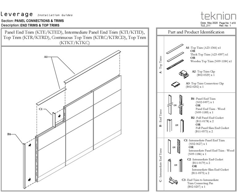
Teknion

Teknion Interpret Operating and maintenance instructions
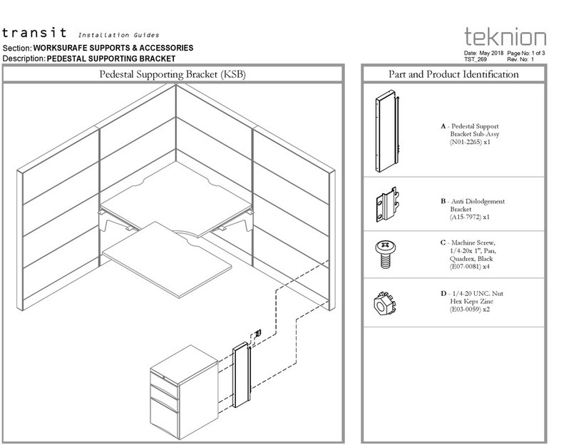
Teknion district 120 Hub HA Worksurface with Connection Kit for hiSpace Quick Connect with District Spine... User manual

Teknion

Teknion district 120 Hub HA Worksurface with Connection Kit for hiSpace Quick Connect with District Spine... User manual

Teknion nuova contessa Owner's manual

Teknion

Teknion nuova contessa Owner's manual

Teknion BSMLHR User manual

Teknion

Teknion BSMLHR User manual

Teknion interpret WWSPK Operating and maintenance instructions
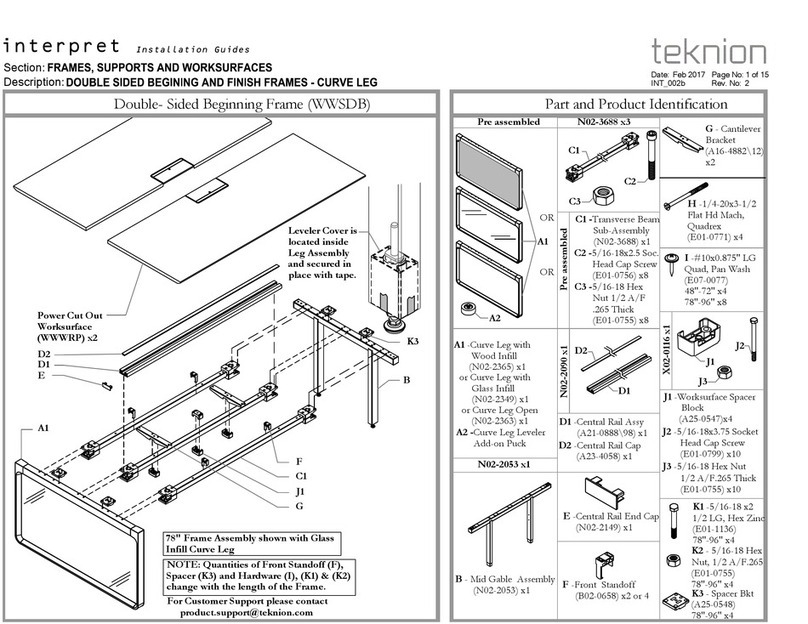
Teknion

Teknion interpret WWSPK Operating and maintenance instructions
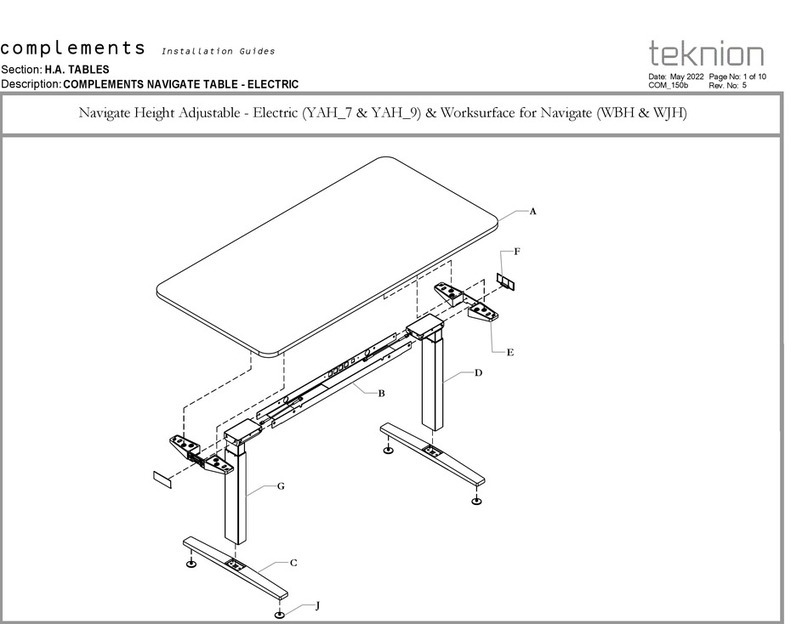
Teknion Leverage Operating and maintenance instructions
Teknion

Teknion Leverage Operating and maintenance instructions
Popular Indoor Furnishing manuals by other brands

miseno Zephyr Cove installation manual

miseno

miseno Zephyr Cove installation manual

Skinact 161341 user manual

Skinact

Skinact 161341 user manual

Trasman CHARLENE 1746 CHIC Assembly manual

Trasman

Trasman CHARLENE 1746 CHIC Assembly manual

Epic Office Furniture NPM-SLEG Assembly instructions

Epic Office Furniture

Epic Office Furniture NPM-SLEG Assembly instructions

Whittier Wood Furniture McKenzie 2363GACa Assembly instructions

Whittier Wood Furniture

Whittier Wood Furniture McKenzie 2363GACa Assembly instructions

IKEA ASPVIK GLASS-DOOR CABINET 20X69" instructions

IKEA

IKEA ASPVIK GLASS-DOOR CABINET 20X69" instructions

Dorel Home Products 4026009 manual

Dorel Home Products

Dorel Home Products 4026009 manual

Tusk ASTON Assembly instructions

Tusk

Tusk ASTON Assembly instructions

VERTBAUDET 70501-1743 manual

VERTBAUDET

VERTBAUDET 70501-1743 manual

OSP furniture 84224 operating instructions

OSP furniture

OSP furniture 84224 operating instructions

Uplift Desk CHR457 instructions

Uplift Desk

Uplift Desk CHR457 instructions

J.Burrows TYPHOON JBSTEALBK Assembly instructions

J.Burrows

J.Burrows TYPHOON JBSTEALBK Assembly instructions

GMI SRI-205 Assembly instructions

GMI

GMI SRI-205 Assembly instructions

Evolur 4100 Assembly instructions

Evolur

Evolur 4100 Assembly instructions

American Standard Moments 2506.011 installation instructions

American Standard

American Standard Moments 2506.011 installation instructions

Cult Balham 5056315930155 Assembly instructions

Cult

Cult Balham 5056315930155 Assembly instructions

LumiSource LS-VIVIDFL XX Assembling instructions

LumiSource

LumiSource LS-VIVIDFL XX Assembling instructions

Coaster 203483 Assembly instructions

Coaster

Coaster 203483 Assembly instructions

manuals.online logo
manuals.online logoBrands
  • About & Mission
  • Contact us
  • Privacy Policy
  • Terms and Conditions

Copyright 2025 Manuals.Online. All Rights Reserved.