manuals.online logo
Brands
  1. Home
  2. •
  3. Brands
  4. •
  5. teko
  6. •
  7. Security System
  8. •
  9. teko Astra-321 User manual

teko Astra-321 User manual

Rev. 321-v3_1_en
Astra-321
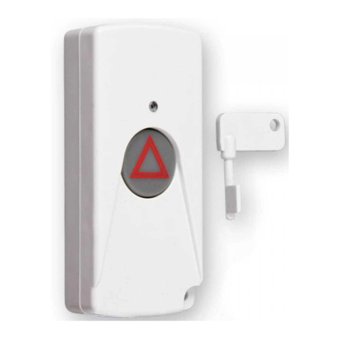
Electro-Contact Panic Button
Operating Manual
The operating manual describes the operating principle, opera-
tional, storage and maintenance conditions pertaining to electro-
contact panic button Astra-321 (hereinafter “detector”) (Fig.1).
The manufacturer reserves the right to make alteration regarding
refinement of the product without prior notification. All changes
will be imported into new edition of the operation manual.
1 Function
The detector is untended for manually switch-
ing on the alarm signal by pressing the button
and transferring the alarm signal to control
panel or notification transmission system.
2 Specifications
Switching voltage, V, max ..........................................................72
Switching current, A, max..........................................................0.2
Overall dimensions, mm………………......……………....87×60×30
Weight, kg, max.......................................................................0.08
Operating Conditions
Temperature range, °С......................................from -30 up to +50
Relative air humidity, %...........................................up to 95 at +25 °С
no moisture condensation
3 Delivery Set
Electro-contact panic button Astra-321................................. 1 pcs.
Key ...................................................................................... 2 pcs.
Screw 3.9x32 (2-4х35) ......................................................... 2 pcs.
Dowel 6х30........................................................................... 2 pcs.
User Instruction .................................................................. 1 copy.
4 Structure
Fig. 2
Structurally, the detector is designed as a unit consisting of a
detachable cover (face side) and a base (Fig. 2).
A printed circuit board with radio elements is mounted on the base.
The detector is equipped with both normally closed and normally
opened contacts.
5 Operating Principle
The detector generates an alarm signal once the detector button
is pressed.
The button is mechanically locked in the “Alarm” status by a
spring.
A key is used to reset the detector to the standby status.
6 Installation and Pre-starting Procedure
6.1 After transportation in conditions differing from those of op-
eration, detector must be kept unpacked for 4 hours in expected
operating conditions.
6.2 The detector shall be mounted in a concealed, discreet loca-
tion for prompt and inconspicuous use.
6.3 Installation Procedure
Step-1
Unscrew the fastening
screw.
Remove the cover
Step-2
Make markings on the place
selected for installation by
using applied base.
Step-3
Remove the blank in the
detector base.
Lead alarm loop wires
through the wire insertion
hole
Step-4
Connect the alarm loop
wires to detector terminals
depending on their function
as per Fig. 3 (normally
closed contacts) or Fig. 4
(normally opened contacts)
Fig. 3
Fig. 4
Step-5
Attach the detector base to
the mounting surface with
two self-driving screws.
Fig. 1
Cover not shown
Mounting
holes
Cover
Screw
terminal
block
Button
Wire insertion
hole
Blank
Lock
Figure 1
Mounting
holes
Blank
2 Rev. 321-v3_1_en
Step-6
Replace the cover and fas-
ten it with the fastening
screw
Step-7
Check detector operability
by pressing the button.
The button shall remain
locked in pressed position
Step-8
To restore the detector to the
standby status, turn the key
6.4 To provide for reliable operation of the alarm system it is rec-
ommended to test the detector at least once a week.
7 Labeling
The following data are shown on the label glued to the body:
- manufacturer trademark;
- detector abbreviated name or designation;
- month and year of manufacture (last two digits);
- conformity mark (if the conformity certificate is available).
8 EC Conformity Declarations
This product is in conformity with the provisions of:
EMC 89/336/EEC
EN 61000-6-3:2005 Electromagnetic compatibility (EMC) - Part 6-
3: Generic standards - Emission standard for residential, com-
mercial and light-industrial environments
EN 50130-4/1995 + A1:1998 + A2:2003 + Corrig. 2003 Alarm
systems - Part 4: Electromagnetic compatibility - Product family
standard: Immunity requirements for components of fire, intruder
and social alarm systems
EN 60950-1: 2001+A11:2004+Corrig.2004 Safety of information
technology equipment.
9 Recycling
The detector does not pose any life or health risk to individuals or
to the environment. Once its service life is complete, the detector
may be utilized with no special environment protection measures.
10 Manufacturer Warranties
10.1 Quality Management System meets provisions of ISO 9001-
2011.
10.2 The manufacturer guarantees the compliance of the detec-
tor with technical requirements provided the transportation, stor-
age, mounting and operating rules and requirements are ob-
served by user.
10.3 The storage warranty period is 2 years and 6 months from
the date of manufacture.
10.4 The operation warranty period is 2 years from the date of
putting into operation but no longer than 2 years 6 months from
the date of manufacturing.
10.5 The manufacturer shall repair or replace a faulty detector
during the warranty period.
10.6 The warranty becomes void if:
- the user does not follow guidelines of the operating manual;
- the detector is mechanically damaged;
- the detector is repaired bya partyother than the Manufacturer.
10.7 The warranty covers the detector only. All equipment manu-
factured by other parties and used with the detector is covered by
its respective warranty.
The manufacturer bears no responsibility for death, injury,
property damage or other incidental or premeditated loss
based on the user's statement that the button has failed to
implement its functions.
Sales:
Controlex GmbH
Warranty service and
technical support:
ТЕКО-TD
Philosophenweg 31-33
47051 Duisburg, Germany
Phone: +49 (0) 203 / 393 91 188
Fax: +49 (0) 203 / 393 91 189
GSM: +49 (0) 178 / 218 48 22
E-mail: info@controlex.eu
Web: www.controlex.eu
Prospekt Pobedy str. 19
420138 Kazan, Russia
Phone: +7 (843) 261-55-75
Fax: +7 (843) 261-58-08
E-mail: info@teko.biz
support@teko.biz
Web: www.teko.biz
Made in Russia

Other teko Security System manuals

teko Astra-Z-6145 User manual

teko

teko Astra-Z-6145 User manual

teko Astra-322 User manual

teko

teko Astra-322 User manual

teko Astra-321 User manual

teko

teko Astra-321 User manual

teko Astra-R User manual

teko

teko Astra-R User manual

teko Astra-10 ver.3 User manual

teko

teko Astra-10 ver.3 User manual

teko astra-10 Installation manual

teko

teko astra-10 Installation manual

teko Astra-R Installation manual

teko

teko Astra-R Installation manual

teko Astra-4511 User manual

teko

teko Astra-4511 User manual

teko Astra-10 Ver.2 Installation instructions

teko

teko Astra-10 Ver.2 Installation instructions

Popular Security System manuals by other brands

inVue OneKEY AKD40 manual

inVue

inVue OneKEY AKD40 manual

Swann DVR8-4200 Specifications

Swann

Swann DVR8-4200 Specifications

Redback A 4574A operating manual

Redback

Redback A 4574A operating manual

Netatmo Smart Indoor Siren user guide

Netatmo

Netatmo Smart Indoor Siren user guide

Konica Minolta SC-508 installation manual

Konica Minolta

Konica Minolta SC-508 installation manual

Firex FADCM manual

Firex

Firex FADCM manual

Antenna Carephone Technical manual

Antenna

Antenna Carephone Technical manual

Pima Hunter-Pro Series installation guide

Pima

Pima Hunter-Pro Series installation guide

Clover CSM-1414Q Specifications

Clover

Clover CSM-1414Q Specifications

Night Owl FS-8320 instruction manual

Night Owl

Night Owl FS-8320 instruction manual

Ksenia Radius installation manual

Ksenia

Ksenia Radius installation manual

IDS X64 Quick programming guide

IDS

IDS X64 Quick programming guide

PA F5K user guide

PA

PA F5K user guide

Speco PVS-1 Operation manual

Speco

Speco PVS-1 Operation manual

SmartPool Pooleye PE20 manual

SmartPool

SmartPool Pooleye PE20 manual

MTB Cameras DV009 instruction manual

MTB Cameras

MTB Cameras DV009 instruction manual

DEI 820T owner's guide

DEI

DEI 820T owner's guide

Risco Agility Installer manual

Risco

Risco Agility Installer manual

manuals.online logo
manuals.online logoBrands
  • About & Mission
  • Contact us
  • Privacy Policy
  • Terms and Conditions

Copyright 2025 Manuals.Online. All Rights Reserved.