TESTO 557 User manual

testo 557 · Digital manifold
Instruction manual
www.GlobalTestSupply.com
Find Quality Products Online at: sales@GlobalTestSupply.com

1 Contents
3
1Contents
1Contents ...................................................................................................3
2Safety and the environment....................................................................4
2.1. About this document........................................................................4
2.2. Ensure safety...................................................................................4
2.3. Protecting the environment..............................................................5
3Product description.................................................................................5
3.1. Use ..................................................................................................5
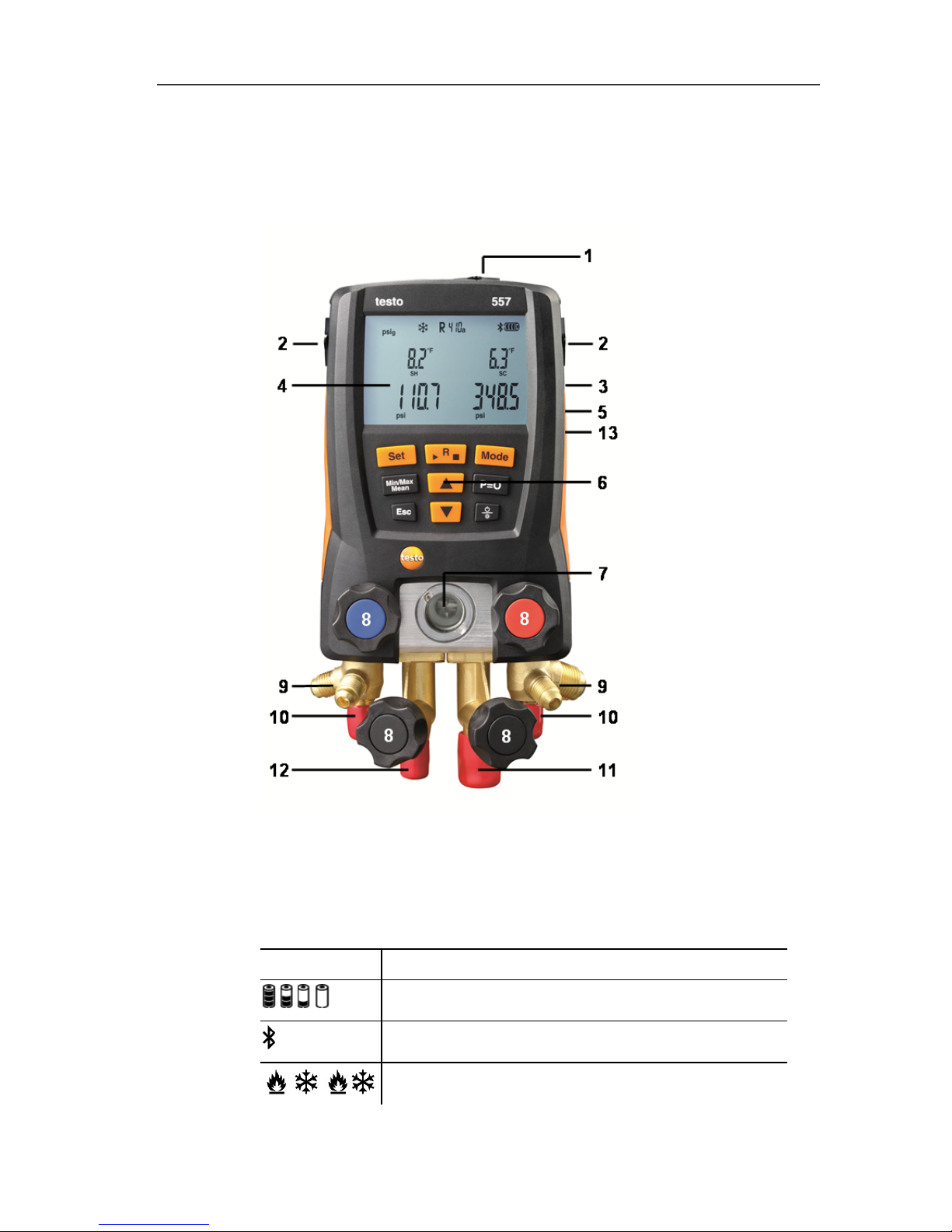
3.2. Overview..........................................................................................6
4First steps ................................................................................................7
5Using the manifold ..................................................................................9
5.1. Preparing for measurement .............................................................9
5.1.1. Switching the instrument on.............................................................................9
5.1.2. Connecting the temperature sensor...............................................................11
5.1.3. Connecting the vacuum probe .......................................................................11
5.1.4. Switching Bluetooth® on and off ....................................................................11
5.1.5. Measuring mode ............................................................................................12
5.2. Performing the measurement ........................................................13
6Technical data........................................................................................16
6.1.1. Bluetooth Modul.............................................................................................16
6.1.2. General technical data ................................................................................... 17
7Maintaining the product ........................................................................19
8Tips and assistance...............................................................................21
8.1. Questions and answers .................................................................21
8.2. Measurement parameters .............................................................21
8.3. Error reports ..................................................................................22
8.4. Accessories and spare parts .........................................................22
9EC declaration of conformity................................................................23
www.GlobalTestSupply.com
Find Quality Products Online at: sales@GlobalTestSupply.com

2 Safety and the environment
4
2Safety and the environment
2.1. About this document
Use
> Please read this documentation carefully and familiarize
yourself with the product before putting it to use. Pay particular
attention to the safety instructions and warning advice in order
to prevent injuries and damage to the product.
Symbols and writing standards
Representation Explanation
Warning advice, risk level according to the
signal word:
Warning! Serious physical injury may occur.
Caution! Slight physical injury or damage to
the equipment may occur.
> Implement the specified precautionary
measures.
Menu Elements of the instrument, the instrument
display or the program interface.
[OK] Control keys of the instrument or buttons of
the program interface.
2.2. Ensure safety
> Do not operate the instrument if there are signs of damage at
the housing, mains unit or hoses.
> Do not store the product together with solvents. Do not use any
desiccants.
> Carry out only the maintenance and repair work on this
instrument that is described in the documentation.
> Dangers may also arise from the refrigeration systems being
measured or the measuring environment: Note the safety
regulations valid in your area when performing the
measurements.
> If the manifold falls or another comparable mechanical load
occurs, the pipe sections of the refrigerant hoses may break.
The valve stem shutoff may also be damaged, whereby further
www.GlobalTestSupply.com
Find Quality Products Online at: sales@GlobalTestSupply.com

3 Product description
5
damage to the interior of the manifold may occur that cannot be
identified from the outside. The refrigerant hoses must therefore
be replaced with new, undamaged refrigerant hoses every time
the manifold falls or following any other comparable mechanical
load. Send the manifold to Testo Customer Service for a
technical check for your own safety.
> To prevent damage from ESD (electro-static discharge) or
transient voltage spikes make sure that your refrigeration
system is properly grounded, as otherwise the manifold might
get damaged.
2.3. Protecting the environment
> Dispose of spent batteries in accordance with the valid legal
specifications.
> At the end of its useful life, send the product to the separate
collection for electric and electronic devices (observe local
regulations) or return the product to Testo for disposal.
> Refrigerant gases can harm the environment. Please note the
applicable environmental regulations.
3Product description
3.1. Use
Testo 557 is a digital manifold for maintenance and service work on
refrigeration systems and heat pumps. It is intended for use by
qualified personnel only.
The function of the testo 557 is designed to replace analog
manifolds, thermometers and pressure/temperature charts.
Pressures and temperatures can be applied, adapted, tested and
monitored.
Testo 557 is compatible with most non-corrosive refrigerants, water
and glycol. Testo 557 is not compatible with refrigerants containing
ammonia.
The instruments must not be used in explosive environments!
www.GlobalTestSupply.com
Find Quality Products Online at: sales@GlobalTestSupply.com

3 Product description
6
3.2. Overview
Display and control elements
1Front connection for external vacuum probe
2Mini-DIN probe socket for NTC temperature probe, with socket
cover
3Foldable hanging hook (on rear)
4Display. Instrument status icons:
Icon Meaning
Battery status
Bluetooth®
// Select measuring mode
www.GlobalTestSupply.com
Find Quality Products Online at: sales@GlobalTestSupply.com

4 First steps
7
5Battery compartment. The rechargeable batteries cannot be
charged inside the instrument!
6 Control keys:
Key Function
[Set] Set units
[R, ►, ■] Select refrigerant / Start-Stop leak test
[Mode] Switch between measuring modes
[Min/Max/Mean] Display min, max, mean values
[▲] Up-key: Scroll through menu.
[P=0] Pressure zeroing
Esc Switches to the measurement/home view.
[▼] Down-key: Scroll through menu.
[/] Switching the instrument on/off
Switching display ilumination on/off.
7Sight glass for refrigerant flow.
84 x valve stem shutoff
94 x hose holders for refrigerant hoses
10 2 x Connection 1/4" SAE, brass.
High pressure, for refrigerant hoses with quick release screw
fitting, passage for valve actuator lockable.
11 Connection 3/8" SAE, brass, for vacuum pump
12 Connection 1/4" SAE, brass, for e.g. refrigerant cylinders
13 Mini-USB connection for firmware update, inside the battery
compartment.
4First steps
Inserting batteries/rechargeable batteries
1. Fold out the hanging hook and open the battery compartment
by squeezing the clip lock.
2. Insert batteries (included in delivery) or rechargeable batteries
(4x 1.5 V, type AA/Mignon/LR6) in the battery compartment.
Observe the polarity!
3. Close the battery compartment.
- After inserting the batteries, the instrument switches on
automatically and goes into the settings menu.
When not in use for long period: Remove batteries /
rechargeable batteries.
www.GlobalTestSupply.com
Find Quality Products Online at: sales@GlobalTestSupply.com

4 First steps
8
Units / Parameter selection
1. Press [Set] to confirm or change unit parameter settings
2. Press [▲]or [▼] to change the units / parameters.
- The settings will be accepted once the last selection has been
made.
Key Functions Description
[▲]or [▼]Change parameters and select units
[Set] Confirm units / parameters
Selectable
parameters
Description
°C, °F Temperature unit
bar, kPa, MPa, psi Unit for pressure.
Pabs, Prel or psig Switch between absolute and relative
pressure display
micron, inHg, Pa,
hPa, mTorr,Torr,
inH2O, mbar
Unit for vacuum pressure.
/ / Select measuring mode: heat pump / cooling
/ or Auto
AUTO OFF Activate or deactivate Automatic power-off.
Instrument switches off after 30 minutes if no
temperature probe is connected and there is
no pressure apart from ambient pressure
Tfac Activate or deactivate surface temperature
compensation factor, icon is shown on the
display if the function is deactivated
- Settings will be applied following the final selection.
Operating the valve stem shutoffs
The digital manifold acts like a conventional two-way manifold with
regard to the refrigerant path: The passages are opened by
opening the valves. The adjacent pressure is measured with valves
closed as well as with them open.
> Open valve: Turn valve positioner counterclockwise.
> Close valve: Turn valve positioner clockwise.
www.GlobalTestSupply.com
Find Quality Products Online at: sales@GlobalTestSupply.com

5 Using the manifold
9
WARNING
Over tightening the valve stem shutoffs may cause:
• Damage to the PTFE seal.
• Mechanical deformation of the valve piston leading to the
PTFE seal falling out.
• Damage to the thread of the threaded spindle and the valve
screw.
• valve knobs to brake.
Lightly tighten the valve knob. Do not use tools to tighten the valve
stem shutoffs.
5Using the manifold
5.1. Preparing for measurement
5.1.1. Switching the instrument on
> Press [/].
Zero the pressure sensors before every measurement.
✓ All connections must be at ambient pressure.
> Press [P=0] key for 3 seconds to execute zeroing.
Connecting the refrigerant hoses
Before each measurement check whether the refrigerant
hoses are in flawless condition.
✓ Make sure the valve stem shutoffs are closed.
1. Connect the refrigerant hoses to the low-pressure side (blue)
and high-pressure side (red).
2. Connect the refrigerant hoses to the AC/R system.
www.GlobalTestSupply.com
Find Quality Products Online at: sales@GlobalTestSupply.com

5 Using the manifold
10
WARNING
Dropping this instrument or any other comparable mechanical
shock can damage the refrigerant pipes and hoses. The valve
actuators may also suffer damage, which in turn could result in
further damage inside the instrument and may not be detectable
from outside.
> For your own safety you should return the manifold to the
Testo Service Department for technical inspection.
> You should therefore always replace the refrigerant hoses with
new ones after an accidental drop has occurred or after any
visible wear and tear.
Choosing the refrigerant
1. Press [R, ►, ■].
- It activates the refrigerant menu and the currently selected
refrigerant flashes.
2. Setting the refrigerant:
Key functions Description
[▲]or [▼]Selectng another refrigerant
[R, ►, ■] Confirm the selection and exit the refrigerant
menu
Available refrigerants
Representation Description
R... Refrigerant number of refrigerant acc. to
ISO 817
--- no refrigerant selected.
Example: Setting refrigerant R401B
1. Press [R, ►, ■]to activate refrigerant menu.
2. Press [▲]or [▼]several times, until R401B flashes.
3. Press [R, ►, ■]to confirm the setting.
Exiting the refrigerant selection
> Press [R, ►, ■]or automatically after 30 s, if no other key has
been pressed.
www.GlobalTestSupply.com
Find Quality Products Online at: sales@GlobalTestSupply.com

5 Using the manifold
11
5.1.2. Connecting the temperature sensor
Surface temperature sensor
At least one NTC temperature probe must be connected to
measure the pipe temperature, for automatic calculation of
superheating and subcooling.
Deactivating the surface compensation factor for insertion and
air temperature sensor
A surface compensation factor has been set in the measuring
instrument to improve the measuring accuracy of surface
temperature readings.
If the manifold is used in combination with insertion or air
temperature probe (optional), this factor must be deactivated:
1. Press [Set] repeatedly until Tfac is displayed.
2. Press [▲]or [▼]to set Tfac to Off.
3. Press [Set] to continue through the settings menu until the
measurement/home view is displayed.
- Tfac is shown on the display if Tfac is disabled.
5.1.3. Connecting the vacuum probe
> Open the front cover of the connector and connect up the
vacuum probe.
5.1.4. Switching Bluetooth® on and off
In order to to establish a connection via Bluetooth, on an Android
or iOS device, the Testo App Refrigeration must be already
installed.
You can get the App for iOS instruments in the App Store or for
Android instruments in the Play Store.
Information about compatibility can be found in the relevant app
store.
1. To turn on the Bluetooth press [▲]and [▼]simultaneously and
hold down for 3 seconds.
- Once the Bluetooth icon is shown on the display, Bluetooth is
switched on.
www.GlobalTestSupply.com
Find Quality Products Online at: sales@GlobalTestSupply.com

5 Using the manifold
12
Display Description
flashes There is no Bluetooth connection, or a
potential connection is being searched for.
is permanently
displayed
There is a Bluetooth connection.
is not displayed Bluetooth is disabled.
2. To turn off the Bluetooth press [▲]and [▼]simultaneously and
hold down for 3 seconds.
- Once the Bluetooth icon is no longer shown on the display,
Bluetooth is switched off.
5.1.5. Measuring mode
Display Mode Function
Refrigeration
system
Normal function of the digital manifold
Heat pump Normal function of the digital manifold
Automatic
mode
If the automatic mode is activated, the
testo 557 digital manifold automatically
changes the display of the high and low
pressure. This automatic change occurs
when the pressure on the low-pressure
side is 1 bar (15 psi) higher than the
pressure on the high-pressure side.
During the change, Load (2 s) is shown
in the display.
This mode is especially suited to air
conditioning systems which cool and
heat (heat pumps).
www.GlobalTestSupply.com
Find Quality Products Online at: sales@GlobalTestSupply.com

5 Using the manifold
13
5.2. Performing the measurement
WARNING
Risk of injury caused by refrigerant that is at high pressure,
hot, cold, or poisonous!
> Wear safety goggles and protective gloves..
> Before pressurizing the measuring instrument: Always fasten
the measuring instrument at the hanging hook in order to
prevent it from falling (risk of breakage)
> Check if the refrigerant hoses are intact and connected
correctly before each measurement. Do not use a tool to
connect the hoses. Only tighten the hoses by hand (max.
torque 5.0 Nm/3.7 ft*lb).
> Do not exceed the permissible measuring range (0 to 870 psi /
0 to 60 bar). Pay particular attention with systems with
refrigerant R744, as these are often operated with higher
pressures.
Measuring
1. Connect and apply pressure to the manifold.
2. See readings.
Note: With refrigerants that have a temperature glide, “Zeotropes”
the evaporation temperature Ev/to and condensation temperature
Co/tc are displayed after evaporation and condensation are
complete.
Zeotropes (refrigerants blends mix together) can separate from
each other, unlike azeotropes which mix together to become one.
Zeoptropes often blend refrigerants with different boiling points
(saturation temps), where one will change from liquid to vapor
before the other as they go through the evaporator. The glide is
the difference between the lowest boiling point and the highest
boiling point. If they are 3 degrees apart, for example, the blend
has a 3 degree glide..
The display illumination will flash if:
• The critical pressure of the refrigerant is within 15 psi (1 bar)
of the highest pressure (and temperature) where the
refrigerant can still condense.
• The maximum. permissible pressure of 870 psi (60 bar) is
exceeded.
www.GlobalTestSupply.com
Find Quality Products Online at: sales@GlobalTestSupply.com

5 Using the manifold
14
Key functions
> Press [▲]
or [▼]to change the reading in the display.
Possible display combinations:
Refrigerant evaporation
temperature Ev/to (°F/°C)
Evaporation pressure
(psi/bar)
Refrigerant condensation
temperature Co/tc (°F/°C)
Condensation pressure
(psi/bar)
Measured temperature T1/t
oh
(°F/°C)
Evaporation pressure
(psi/bar)
Measured temperature T2/t
cu
(°F/°C)
Condensation pressure
(psi/bar)
Superheating SH/∆t
oh
(°F/°C)
Evaporation pressure
(psi/bar)
Subcooling SC/∆t
cu
(°F/°C)
Condensation pressure
(psi/bar)
With both NTC temperature probes connected, ∆t is also shown.
> Press [Mean/Min/Max]: to display min. / max. readings and
mean values.
Leak test / pressure drop test
Systems can be tested for tightness with the temperature-
compensated leak test. The system pressure and the ambient
temperature are measured over a defined period of time, typically
with an inert gas such as Nitrogen. A temperature probe can be
connected that measures the ambient temperature. : Optional air
temperature probe, part. no. 0613 1712) is recommended.
Measurement data of the temperature-compensated differential
pressure and temperature, from start to the end of the test, is
displayed. It is possible to perform a leak test without connecting a
temperature probe.
Changeable
- Evaporation
Temperature (Ev)
- Measured
Temperature (T1)
- Superheating
(SH)
Changeable
- Condensation
Temperature (Co)
- Measured
Temperature (T2)
- Subcooling (SC)
Condensation
pressure
Evaporation
pressure
www.GlobalTestSupply.com
Find Quality Products Online at: sales@GlobalTestSupply.com

5 Using the manifold
15
1. Press [Mode] ∆P is displayed.
2. Start the leak test: Press [R, ►, ■].∆Pis now flashing and
hh:mm timer is on.
3. End the leak test: Press [R, ►, ■].∆Pstops flashing and
hh:mm timer stops.
- Result is displayed. Note: Leak test time duration and ∆P value
4. Confirm the message: Press [Mode] to exit leak mode.
Vacuum measurement
✓The vacuum probe is plugged into the front connection of the
manifold and connected to the system.
1. Press [Mode] the vacuum mode is displayed.
If ambient pressure is applied to the vacuum probe, then oooo is
shown on the display.
2. Start the vacuum pump.
- Once the measuring range 0 to 20,000 microns is reached, the
current vacuum value is shown on the instrument display. The
instrument also displays the current ambient temperature, the
water evaporation temperature, which corresponds to the
vacuum reading, and the delta between these two
temperatures.
3. To leave vacuum mode, remove the vacuum probe from the
testo 557 or switch to the standard measurement view using the
[Mode] button.
Differential
pressure start
compared to
actual
Measured
pressure
beginning
of test
Duration
of test
A
ctual
measured
pressure
www.GlobalTestSupply.com
Find Quality Products Online at: sales@GlobalTestSupply.com

6 Technical data
16
6Technical data
6.1.1. Bluetooth Modul
The Bluetooth®option may only be operated in countries in
which it is type approved.
Feature Values
Bluetooth Range >20 m (free field)
Bluetooth type LSD Science & Technology Co., Ltd
L Series BLE Module (08 Mai 2013) based
on TI CC254X chip
Qualified Design ID B016552
Bluetooth radio
class
Class 3
Bluetooth company 10274
European Union
Austria, Belgium, Bulgaria, Croatia, Cyprus, Czech Republic,
Denmark, Estonia, Finland, France, Germany, Greece, Hungary,
Ireland, Italy, Latvia, Lithuania, Luxembourg, Malta, Netherlands,
Poland, Portugal, Romania, Slovakia, Slovenia, Spain, Sweden,
United Kingdom.
EFTA countries
Island, Suisse, Norway, Lichtenstein.
Other countries
USA, Turkey, Hong Kong, Canada
Information from the FCC (Federal Communications Commission)
This device complies with part 15 of the FCC Rules. Its
commissioning is subject to the two following conditions: (1) This
instrument must not cause any harmful interference and (2) this
instrument must be able to cope with interference, even if this has
undesirable effects on operation.
Changes
The FCC demands that the user be informed that any changes or
modifications to the instrument that are not explicitly approved by
Testo AG may void the user's right to use this instrument.
www.GlobalTestSupply.com
Find Quality Products Online at: sales@GlobalTestSupply.com

6 Technical data
17
6.1.2. General technical data
Feature Values
Parameters
Pressure: psi / kPa / MPa / bar
Temperature: °F / °C / K
Vacuum: micron / inHg / inH2O / hPa / mbar /
mTorr /Torr / Pa
Sensors 2 Pressure: sensors, 2 Temperature (NTC
Thermistors)
Measuring cycle 0.5 s
Interfaces
Pressure connections: 3 x 1/4" SAE, 1x 3/8" SAE
NTC measurement
External vacuum probe
Measuring
ranges
Pressure measurement range
HP/LP: -14.7…870 psi / -100…6000 kPa
/ -0.1…6 MPa / -1…60 bar (rel)
Temperature measurement range: -58…302 °F
/ -50…+150 °C
Measurement range vacuum (abs):
0 … 20.000 micron
Overload 940 psi, 65 bar, 6500 kPa, 6.5 MPa
Resolution
Resolution pressure: 0.1 psi / 0.01 bar / 1 kPa /
0.001 MPa
Resolution temperature: 0.1 °F / 0.1 °C / 0.1 K
Vacuum resolution:
1 micron (from 0 to 1000 micron)
10 micron (from 1000 to 2000 micron)
100 micron (from 2000 to 5000 micron)
500 micron (from 5000 to 10000 micron)
5000 micron (from 10000 to 20.000 micron)
Accuracy
(nominal
temperature
71.6 °F / 22 °C)
Pressure: ±0.5% FS (±1 digit)
Temperature: -58 to 302°F (0.9°F ± 1 digit) / -50
to 150°C (±0.5 °C ±1 digit)
Vacuum: ±10% of rdg +10 microns (100 to 1.000
microns)
No. of
refrigerants
60
www.GlobalTestSupply.com
Find Quality Products Online at: sales@GlobalTestSupply.com

6 Technical data
18
Feature Values
Selectable
refrigerants
No refrigerant, R11, R12, R22, R123, R1234ze,
R125, R13B1, R134a, R14, R142B, R152a,
R161, R23, R227, R290, R32, R401A, R401B,
R401C, R402A, R402B, R404A, R406A, R407A,
R407B, R407C, R407D, R407F, R408A, R409A,
R410A, R411A, R412A, R413A, R414B, R416A,
R417A, R420A, R421A, R421B, R422A, R422B,
R422C, R422D, R424A, R426A, R427A, R434A,
R437A, R438A, R502, R503, R507, R508A,
R508B, R600, R600a, R718 (H2O), R744 (CO2)
(only in permissible measurement range up to
60 bar), R1234yf
Measurable
media
All refrigerants that are stored in the testo 557
Ammonia (R717) and other refrigerants which
contain ammonia will damage the manifold
Ambient
conditions
Operating temperature: -4…122°F / -20…50°C
14…122°F / -10…50°C (vacuum probe)
Storage temperature: -4…140°F / -20…60°C
Humidity in area of use: 10… 90%rF
Bluetooth Range >20 m / 65 ft (unobstructed field)
Housing
Material: ABS / PA / TPE
Dimensions approx. 280 x 135 x 75 mm
Weight: approx. 1200 g (without batteries)
IP-class 42
Power supply
4 x 1.5 V, type AA/mignon/LR6 rechargeable or
standard batteries
Battery life: approx. 250h
(display light off, Bluetooth off, vacuum probe not
connected)
Display Type: Illuminated LCD
Response time: 0.5 s
Directives,
standards and
tests
EC Directive: 2014/30/EC
Warranty
Duration: 2 years
Terms of warranty: see website
www.testo.com/warranty
www.GlobalTestSupply.com
Find Quality Products Online at: sales@GlobalTestSupply.com

7 Maintaining the product
19
7Maintaining the product
Cleaning the instrument
Do not use harsh cleaning agents or solvents! Mild soap and
water may be used.
> Clean instrument using a damp cloth.
Keeping connections clean
> Keep screw connections clean and free of grease and other
deposits, clean with a moist cloth as required.
Removing oil residues
> Carefully blow out oil residues in valve block using compressed
air.
To ensure measuring accuracy
> Check instrument regularly for leaks (recommended: annually).
Keep to the permissible pressure range!
> Calibrate instrument regularly (recommended: annually).
Changing batteries/rechargeable batteries
✓Instrument is switched off.
1. Fold out the hook, loosen the clip and remove the cover of the
battery compartment.
2. Remove discharged batteries/rechargeable batteries and insert
new batteries/rechargeable batteries (4x 1.5 V, type AA,
Mignon, LR6) in the battery compartment. Observe the polarity!
3. Set on and close cover of the battery compartment (clip must
engage).
4. Switch the instrument on.
www.GlobalTestSupply.com
Find Quality Products Online at: sales@GlobalTestSupply.com

7 Maintaining the product
20
Changing the valve or valve stem shutoff
Replacement of valve stem shutoffs or valves must be performed
by a qualified technician. Warranty coverage with respect to valve
stem shut-offs and valves will NOT apply to miss-use or damage
and is only applicable if failure is attributable to defective parts and
workmanship.
Send the measuring instrument to Testo Customer Service.
Cleaning the vacuum probe
Contaminants such as oil may impair the accuracy of the vacuum
sensor.
CAUTION
Carrying out cleaning with the probe connected may result in
damage to the probe!
> Remove the vacuum probe from the testo 557!
CAUTION
Damage to the sensor due to sharp objects!
> Do not insert any sharp objects into the probe!
1. Remove the vacuum probe from the testo 557.
2. Put a few drops of rubbing alcohol into the sensor opening.
3. Seal the opening by placing your finger on it and shake the
vacuum probe briefly.
4. Remove all the alcohol from the probe.
5. Repeat this process at least twice.
6. Leave the probe to dry for at least 1 hour. To dry the sensor
faster, you can connect the probe directly to a vacuum pump
and draw vacuum.
www.GlobalTestSupply.com
Find Quality Products Online at: sales@GlobalTestSupply.com

8 Tips and assistance
21
8Tips and assistance
8.1. Questions and answers
Question Possible causes/solution
flashes Batteries are almost empty.
> Change batteries.
The instrument switches
off automatically.
Residual capacity of the batteries is too
low.
> Change batteries.
uuuu lights up instead of
the parameter display
The permissible measuring range has
been undershot.
> Keep to the permitted measuring
range.
oooo lights up instead of
the parameter display
The permissible measuring range has
been exceeded.
> Keep to the permitted measuring
range.
8.2. Measurement parameters
Name Description
bar, °C psi, °F
∆toh SH Superheating, evaporation pressure
∆tcu SC Subcooling, condensation pressure
to Ev Refrigerant evaporation temperature
tc Co Refrigerant condensation temperature
toh T1 Measured temperature, evaporation
tcu T2 Measured temperature, condensation
www.GlobalTestSupply.com
Find Quality Products Online at: sales@GlobalTestSupply.com
Other manuals for 557
4
Table of contents
Other TESTO Test Equipment manuals
Popular Test Equipment manuals by other brands

Promax
Promax TV EXPLORER HD+ Quick reference guide

Kyoritsu Electrical Instruments Works, Ltd.
Kyoritsu Electrical Instruments Works, Ltd. KEW SNAP Series instruction manual

Kyoritsu Electrical Instruments Works, Ltd.
Kyoritsu Electrical Instruments Works, Ltd. 6050 instruction manual

red lion
red lion IAMS 0001 manual

Mikrom
Mikrom K73a manual

EMTEST
EMTEST AN 200 Series Manual for operation