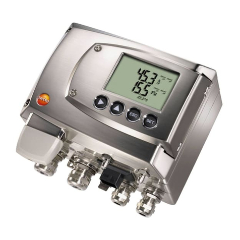
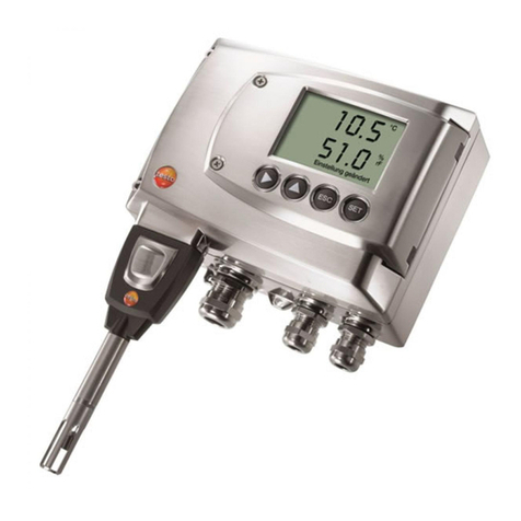
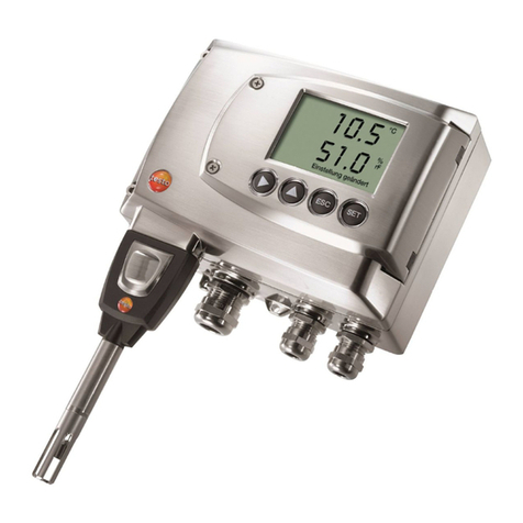
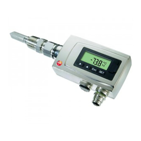
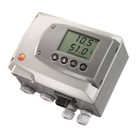
TESTO 6681 Profibus User manual

testo 6681 · Humidity transmitters
testo 6610 · Probes
P2A software · Parameterizing, adjusting and analyzing
software
Instruction manual Volume 2
en


Contents
71
Contents
2TESTO 6610 PROBES ............................................................................... 73
2.1 Specifications......................................................................................... 73
2.1.1 Functions and use.....................................................................73
2.1.2 Design of the probe ...................................................................75
2.1.3 Accessories...............................................................................76
2.2 Product description ................................................................................76
2.2.1 Overview of probe and filter types ............................................76
2.2.2 testo 6611 wall probe ................................................................ 81
2.2.3 testo 6612 duct probe ...............................................................84
2.2.4 testo 6613 cable probe..............................................................88
2.2.5 testo 6614 heated cable probe .................................................92
2.2.6 testo 6615 trace humidity cable probe (self-adjustment) ..........95
2.2.7 testo 6617 cable probe (self-monitoring) ..................................99
2.3 Commissioning ....................................................................................103
2.3.1 Installing the probe..................................................................103
2.3.2 Connecting/removing the probe to/from the transmitter .........107
2.4 Maintenance and cleaning................................................................... 107
2.4.1 Replacing filters/protection caps .............................................107
2.4.2 Cleaning the instrument and filter/protection cap ...................110
2.4.3 Replacing the sensor ..............................................................110
3PARAMETERIZING,ADJUSTING AND ANALYZING SOFTWARE (P2A SOFTWARE)
............................................................................................................. 111
3.1 Specifications....................................................................................... 111
3.1.1 Functions and use...................................................................111
3.1.2 System requirements ..............................................................112
3.1.3 Scope of delivery.....................................................................113
3.2 First steps ............................................................................................ 113
3.2.1 Installing the software/driver ...................................................113
3.2.2 Starting the software ...............................................................114
3.3 Using the software ...............................................................................115
3.3.1 User interface.......................................................................... 115
3.3.2 Editing instrument/parameter file ............................................117
3.3.3 Analyzing/testing the transmitter .............................................127
3.3.4 Adjusting the transmitter .........................................................133
3.3.5 Transmitter history ..................................................................138

72
Contents
4TIPS AND ASSISTANCE ........................................................................... 144
4.1 Questions and answers ....................................................................... 144
4.2 Accessories and spare parts ............................................................... 145
4.2.1 Ordering options for testo 6681 transmitter (0555 6681).................. 148
4.2.2 Ordering options for testo 6610 probes (0555 6610)...................... 152

testo 6610 - 2.1 Specifications
73
2 testo 6610 probes
2.1 Specifications
2.1.1 Functions and use
The plug-in, adjusted probes from the testo 6610 range are used in
conjunction with the testo 6681 humidity transmitter.
These measuring units are suitable for the following applications, for
example:
•Process instrumentation
•Clean rooms
•Test benches
•Drying processes
•Production and storage air quality
•Complex room climate applications.
2.1.1.1 Digital probes:
The probes are adjusted in the factory and transmit their adjustment data to
the internal memory of the testo 6681 transmitter. The information is
transmitted between the probe and transmitter in a purely digital form. The
probes can therefore be disconnected from the transmitter for adjustment or
servicing while the transmitter itself can remain at the measuring point.
Hint:
We recommend in this case that a probe of the same type be
inserted into the transmitter immediately in order to be able to
continue measuring with minimal interruption.
The transmitter identifies the probe and records that a probe was connected
in the history.
The testo 6681 transmitter cannot be run with the testo 6600
probes; testo 6610 probes must be used.

74
testo 6610 - 2.1 Specifications
2.1.1.2 The Testo humidity sensor
With the Testo humidity sensor, which has been in successful use and
continually improved for more than twenty years, the focus has from the very
beginning been on both accuracy parameters, namely measuring uncertainty
and long-term stability.
The capacitive humidity sensor is in principle a plate capacitor consisting of
two electrically conductive plates (electrodes (1) and (2), see diagram below)
opposite each other.
A humidity-sensitive polymer (5) serves as the dielectric. The special feature
lies in the perfect way the individual layers are matched to each other. This is
evident particularly in the top electrode, which has to perform two tasks that,
at first glance, appear contradictory: it must be completely permeable to the
water vapour that is to be fed into the polymer dielectric, but at the same time
it must be impervious, smooth and repellent to condensate, oil and dirt in
order to protect the sensor.
1 Cover electrode
2 Bottom electrode
3 Substrate
(Ceramic substrate for
mechanical protection)
4 Connections
(protected against corrosion)
5 Dielectric layer
The humidity sensor cannot be exchanged by the customer.
The humidity sensor may not be damaged or touched.
Contamination and damage lead to an impairment of the
measurement and the measuring accuracy.

testo 6610 - 2.1 Specifications
75
2.1.1.3 Self-diagnosis
The probes in the testo 6610 range monitor their functionality themselves and
report the following faults:
•Sensor breaks
•Sensor short-circuit
•Condensation
The condensation message is issued at a reading of 100 % RH and
deactivated once the readings are within the valid range.
•Error message with drift at the adjustment points
•Value for relative humidity less than 0 % RH.
The trigger threshold is set at -2 % RH. This means that an error
message is only issued once a clear effect is discernible.
•Early warning when sensor corrosion is starting to develop
The testo 6617 probe is able to signal the first signs of corrosion. The
probe can thus be changed at an early stage without interrupting the
machine availability.
•Self-adjustment (testo 6615 only)
•Excess temperature
Error message if permissible process temperature is exceeded
2.1.2 Design of the probe
The probes of the testo 6610 range are made up of the following components
(included in delivery):
•Probe connector
•Probe shaft with protection cap and sensors (% RH and °C or °F)
•Mounting bracket (for testo 6612 duct version)
•Probe cable (testo 6612 to 6617, duct and cable version), bend radius
minimum Ø50 mm

76
testo 6610 - 2.2 Product description
2.1.3 Accessories
The following accessories are available for probes in the testo 6610 range:
•Filters and protection caps (see chapter 2.2.1.4).
•Calibration certificates according to ISO and DAkkS (see chapter 4.2,
Accessories and spare parts).
2.2 Product description
2.2.1 Overview of probe and filter types
2.2.1.1 Probe version
A detailed description of the probe versions can be found
from chapter 2.2.2 onwards.
The following probe versions are available for the testo 6681 humidity
transmitter:
Version
Article no.
Characteristic
testo 6611 0555 6610-L11 Wall probe version; accuracy to ± 1 % RH;
temperature range -20 °C to +70 °C/-4 to +158 °F
testo 6612 0555 6610-L12 Duct probe version; accuracy to ± 1 % RH;
temperature range -30 °C to +150 °C/-22 to +302 °F
testo 6613 0555 6610-L13 Cable probe version; accuracy to ± 1 % RH;
temperature range -70 bis +180 °C/-94...+356 °F
probe
Probe connector
Probe length
Probe
Protection cap,
sensor underneath

testo 6610 - 2.2 Product description
77
Version
Article no.
Characteristic
testo 6614 0555 6610-L14 Heated cable probe version; accuracy to ± 1%RH;
temperature range -40 °C to +180 °C/
-40 to +356 °F
testo 6615 0555 6610-L15 Trace humidity cable probe version;
dew point to -60 °Ctd;
temperature range -40 °C to +120 °C/-40 to
+248 °F
testo 6617 0555 6610-L17 Cable with cover electrode monitoring probe
version; accuracy ± 1.2 % RH; temperature range -
40 °C to +180 °C/-40 to +356 °F
2.2.1.2 Determining the accuracy/measuring uncertainty
The entries for the measuring uncertainty for the probe are determined in
accordance with GUM (Guide to the Expression of Uncertainty in
Measurement/DIN V ENV 13005). All parts that make up the measuring
uncertainty given by Testo are listed below. When comparing the measuring
uncertainty/accuracy between manufacturers, which components are
included is to be taken into account. In many cases, not all elements that
contribute to measuring uncertainty are assessed, for example if the error
contribution of the production adjustment is shown separately or not at all.

78
testo 6610 - 2.2 Product description
The measuring uncertainty of the probe includes the sensor and its
electronics as well as the output of the digital measuring signal:
1. Linearity including scatter
Systematic error and scattering of the
components (due to manufacturing
tolerances)
2. Hysteresis
Hysteresis indicates the maximum
deviation of the readings that are
obtained when you set the same value for
the parameter, once coming from a
smaller value, once coming from a larger
value (humidity sensors actually have no
hysteresis, but rather very slow
adjustment effects that appear to be
hysteresis when considered only for a
short period.)
3. Reproducibility
Repeatability (scattering of the readings
in the event of the same parameter being
entered successively)
4. Production adjustment area
The measuring uncertainty of the
reference instruments of the adjustment
area (including the reference instrument)
in production
5. Uncertainty of the testing
Uncertainty of the procedure for
determining points 1 and 2.

testo 6610 - 2.2 Product description
79
2.2.1.3 Ordering options for testo 6610 probes
(0555 6610)
Order code
Characteristic
Lxx Probe type
L 11
Probe 6611
L 12
Probe 6612
L 13
Probe 6613
L 14
Probe 6614
L 15
Probe 6615
L 17
Probe 6617
Mxx Protective
filter
M 01
Stainless steel sintered filter
M 02
Metal wire protection cap
M 03
Sintered PTFE filter
M 04
Open metal protection cap
M 05
ABS plastic cap (open)
M 06
PTFE filter with drip hole
M 07
PTFE filter with drip hole and condensation protector
M 08
Filter for H
2
O
2
atmospheres
Nxx Cable length
N 00
Without cable (testo 6611)
N 01
1 m cable length (testo 6613, 6614, 6615, 6617)
N 02
2 m cable length (testo 6613, 6614, 6615, 6617)
N 05
5 m cable length (testo 6613, 6614, 6615, 6617)
N 10
10 m cable length (testo 6613, 6614, 6615, 6617)
Pxx Probe length
P 07
Probe length approx. 70 mm (testo 6611)
P 12
Probe length approx. 120 mm (testo 6613)
P 20 Probe length approx. 200 mm (testo 6611, 6612, 6613,
6614, 6615, 6617)
P 30
Probe length approx. 300 mm (testo 6612, 6613, 6614)
P 50 Probe length approx. 500 mm (testo 6612, 6613, 6614,
6615, 6617)
P 80
Probe length approx. 800 mm (testo 6612, 6613)

80
testo 6610 - 2.2 Product description
2.2.1.4 Filters
One of the following filters or protection caps can be used for each probe
version:
Filter*
Article no.**
Characteristic
Length A (mm)
M 01
0554 0647
Stainless steel sintered filter
33
M 02
0554 0757
Metal wire protection cap
40,3
M 03
0554 0759
Sintered PTFE filter
35
M 04
0554 0755
Open metal protection cap
35
M 05 0192 0265 Open ABS plastic cap 25
M 06
0554 9913
PTFE filter with drip hole
35
M 07 0554 9913 +
0554 0166
PTFE filter with drip hole and
condensation protector
35
55
M 08
0554 6000
Filter for H
2
O
2
atmospheres
35
* When ordering the probe, please use this filter code, cf. chapter 2.2.1.3, Ordering
options for testo 6610 probes (0555 6610).
** When purchasing a replacement (filters only), please use this order number

testo 6610 - 2.2 Product description
81
2.2.2 testo 6611 wall probe
The wireless testo 6611 probe is inserted into the testo 6681 humidity
transmitter that is mounted on the wall and ready-wired.
At a glance
Application
•Monitoring and regulating the production and storage air quality when
manufacturing and storing hygroscopic products
•Meeting the top accuracy requirements
•Clean room applications for which a metal housing is required.
L-A
A
L
testo 6681 transmitter
testo 6611 wall probe
E
1 Filter (including: humidity
and temperature sensor)
2
Probe shaft
3
Key
4
Connector
E

82
testo 6610 - 2.2 Product description
Technical Data
Parameters
-Humidity (% °Ctd/°Ftd), etc.
-Temperature
Measuring range
-Humidity: 0 to 100 % RH1
-Temperature: -20 to +70 °C/4 to
+158 °F
Material
-Probe shaft: Stainless steel
-Connector: ABS plastic
Accuracy (at 25 °C/77 °F)*
Length 200 mm
Humidity
-± (1,0 % RH + 0.007 x reading) for
0 to 90 % RH
-± (1,4 % RH + 0.007 x reading) for
90 to 100 % RH
-0.02 % RH/K, dependent upon the
process temperature
(with a deviation of 25 °C/+77 °F)
-0.02 % RH/K, dependent upon the
electronics temperature
(with a deviation of 25 °C/+77 °F)
Temperature
-±0.15 °C (0.27 °F)
with slope PT1000 class AA
* Refer to the charts below for the
correlation between temperature
and accuracy.
Length 70 mm
As with length of 200 mm, but with
additional measuring error, specified
for the operating mode 2 channels at
12 mA, without display light, relay off:
Humidity: ±1.6 % RH (additional)
Temperature: ±0.6 °C / ±1.1 °F
(additional)
Reproducibility
-Better than ±0,2 % RH
Sensor
Response time without protective
filter: t 90 max. 15 sec.
Probe dimensions
-Diameter of probe shaft: 12 mm
-E = 55 mm
-L = approx. 70 mm or 200 mm
-L – A = 35 mm or 165 mm
-A, see Table Filters, chapter
2.2.1.4.
1For constant use in high humidity (> 80% rF at ≤ 30°C for
> 12 h, > 60% rF at > 30°C for > 12 h), please contact us via
www.testo.com/service-contact

testo 6610 - 2.2 Product description
83
Measuring accuracy of testo 6611 wall probe
Humidity error according to amount |±% RH| as a factor of process humidity
Temperature error as a factor of process temperature and temperature of
electronics
% RH
% RH
System error 6681 + probe, electronics 25 °C/+77 °F
System error 6681 + probe, electronics -25 °C to +70 °C/-13 to
158 °F

84
testo 6610 - 2.2 Product description
2.2.3 testo 6612 duct probe
The testo 6612 probe measures the humidity and temperature in air ducts.
At a glance
In the event of overpressures, the probe may become a
projectile.
For assembly, see Pressure resistance on the following
page.
1 Filter (including: humidity
and temperature sensor)
2
Probe shaft
3
Wall/duct holder
(accessories,
Order no.: 0554 6651)
4
Mounting bracket
(permanently joined to
probe shaft)
5
Probe cable
6
Key
7
Connector

testo 6610 - 2.2 Product description
85
Application
•Monitoring and regulating the production and storage air quality in air
ducts when manufacturing and storing hygroscopic products
•Meeting the top accuracy requirements
•Air duct applications for which a metal housing is required.
testo 6681 transmitter
testo 6612 duct probe
Technical Data
Parameters
-Humidity (% RH/°Ctd/°Ftd), etc.
-Temperature
Measuring range
-Humidity: 0 to 100 % RH2
-Temperature: - 30 to +150 °C/-22
to +302 °F
Material
-Probe shaft: Stainless steel
-Line: Sheathed, FEP
-Connector: ABS plastic
Accuracy (at 25°C/77°F)*
Humidity
2For constant use in high humidity (> 80% rF at ≤ 30°C for
> 12 h, > 60% rF at > 30°C for > 12 h), please contact us via
www.testo.com/service-contact
-± (1,0 % RH + 0.007 x reading) for
0 to 90 % RH
-± (1,4 % RH + 0.007 x reading) for
90 to 100 % RH
-0.02 % RH/K, dependent upon the
process temperature
(with a deviation of 25 °C/+77 °F)
-0.02 % RH/K, dependent upon the
electronics temperature
(with a deviation of 25 °C/+77 °F)
Temperature
-±0.15 °C (0.27 °F)
Slope PT1000 class AA
* Refer to the charts below for the
correlation between temperature
and accuracy.

86
testo 6610 - 2.2 Product description
Reproducibility
-Better than ±0,2 % RH
Sensor
Response time without protective
filter: t 90 max. 15 sec.
Probe dimensions
-Diameter of probe shaft: 12 mm
-L = approx. 200/300/500/800 mm
-L – A = 165/265/465/765 mm
-A, see Table Filters, chapter
2.2.1.4.
Cable length incl. probe shaft and
filter
-Customized for duct version
Pressure resistance
-PN 10 (probe tip)**
** If installing probe under pressure,
please use cutting ring screw
connection (order no. 0554 1795).
Measuring accuracy of testo 6612 duct probe
Humidity error according to amount |
±
% RH| as a factor of process
humidity
% RH
% RH

testo 6610 - 2.2 Product description
87
Temperature error as a factor of process temperature and temperature of
electronics
System error 6681 + probe, electronics 25 °C/+77 °F
System error 6681 + probe, electronics -25 °C to +70 °C/-13 to +158 °F

88
testo 6610 - 2.2 Product description
2.2.4 testo 6613 cable probe
The testo 6613 probe is used when the spatial separation of the transmitter
and probe is required.
At a glance
In the event of overpressures, the probe may become a
projectile.
For assembly, see Pressure resistance on the following
page.
Application
•Monitoring and regulating industrial humidity processes (apart from
high-humidity processes), e.g. food production, storing fruit
•Monitoring the production and storage air quality when manufacturing
and storing hygroscopic products
•Meeting the top accuracy requirements
•Clean room applications
•Applications for which a sturdy metal housing is required.
1 Connector
2
Key
3
Probe cable
4
Probe shaft
5
Filter (including: humidity
and temperature sensor)
1
2
3
5
4
Other manuals for 6681 Profibus
4
This manual suits for next models
1
Table of contents
Other TESTO Transmitter manuals
Popular Transmitter manuals by other brands

Valcom
Valcom T7C Series manual

Genie
Genie WTX-4BH-26 quick start guide

Micatrone
Micatrone Micaflex PFTT Installation & operation manual

HK Instruments
HK Instruments CDT-MOD-2000 Series installation instructions

Linx
Linx MS Compact user guide

Nice
Nice MYGO2BD Instructions and warnings for installation and use