TESTO 0555 4444 User manual

Instruction manual
Flow transmitter
0555 4444 / 0699 5100/1...5

Imprint
2
This documentation is subject to the copyright of Testo AG.
Reproduction and employment contrary to the justified interests of
Testo AG are prohibited without the prior, written consent of the
company.
We reserve the right to modify technical details in the descriptions,
specifications and illustrations contained in this documentation.
Testo AG
Postfach 11 40
D-79849 Lenzkirch

Preface / General notes
Preface
Dear Testo customer,
Congratulations for choosing a Testo product. We hope that you will enjoy many years of using the
product and that it will help you in your work.
Please read these operating instructions carefully and familiarise yourself with the operation of the unit
before putting it to use.
If problems should occur which you cannot rectify yourself, please consult our service department or
your dealer. We will endeavour to provide fast and competent assistance to save you long downtimes.
General notes
Assembly, electrical installation and commissioning should only be carried out by suitably trained
authorised personnel.
You must always comply with the regulations applicable in your country to the opening and repair of
electrical equipment.
Warnings and particularly important information which you must note when handling the product are
identified in this instruction manual as follows:
Pictograms
Warnings are identified by means of a warning triangle. The relevant signal word! indicates the degree
of risk:
Warning! means: Serious physical injury could occur if you do not take the precautionary
measures indicated.
Caution! means: Slight physical injury or material damage could occur if you do not take
the precautionary measures indicated.
Pay particular attention to warnings and take the precautionary measures indicated in
order to avoid danger.
Notes on special cases and peculiarities in the handling of your unit are indicated by an exclamation
mark.
Standards / Tests
As declared in the certificate of conformity, this unit fulfils the guidelines of 2004 / 108 / EC.
3
Signal word!

Content
4
Imprint ..................................................................................2
Preface / General notes ........................................................3
Content ................................................................................4
1. Fundamental safety instructions ............................................5
2. Product description ..............................................................6
3. Measuring instrument dimensions ........................................6
4. Advantages of the flow transmitter........................................7
5. Standard versions ................................................................7
6. Version options ....................................................................8
7. Compensation for thermal probes ........................................9
8. Configuration of connections ..............................................10
9. Connection ........................................................................11
9.1 Description of the 4-wire system ........................................11
9.2 Current/voltage measurement (4-wire system) ....................11
10. Troubleshooting ..................................................................12
11. Technical data ....................................................................13
12. Accessories ........................................................................14

1. Fundamental safety instructions
5
Please read the following safety instructions with care:
Avoid electrical hazards:
Never make measurements with the unit and its external probes on or near live components unless
the unit is expressly approved for current and voltage measurements.
Damaged mains cables must only be replaced by authorised personnel.
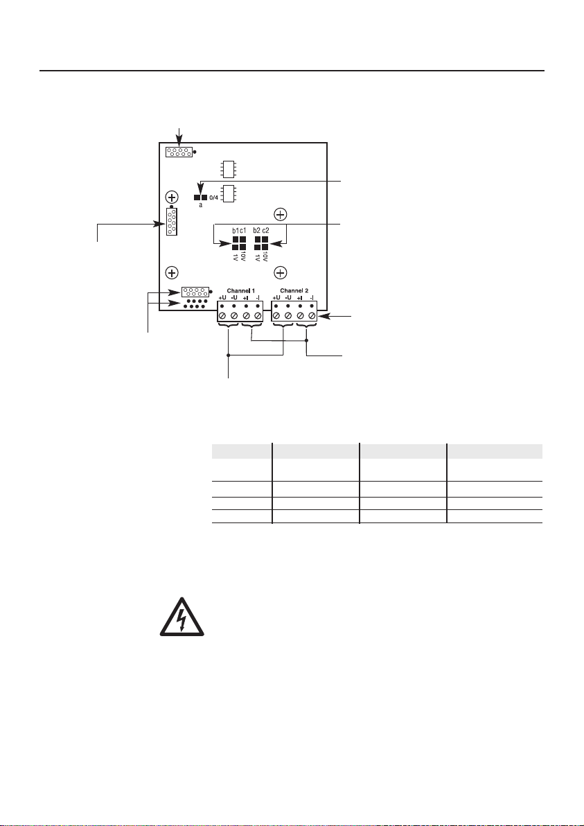
The transmitter should be wired when disconnected.
You must always comply with the regulations applicable in your country to the opening and repair of
electrical equipment.
Protect the instrument:
Note the measuring ranges of the sensor! Overheating will destroy the probes.
Keep to the admissible storage and transport temperature and the permitted operating temperature!
Product safety / preserving warranty claims:
Operate the instrument only within the parameters specified in the technical data.
Handle the instrument properly and according to its intended purpose.
Never apply force!
Do not use the device for control purposes at the same time as operating or servicing the transmitter.
Open the instrument only when this is expressly described in the Operating Instructions for
maintenance purposes.
Carry out only the maintenance and repair work that is described in the instruction manual. Follow
the prescribed steps exactly. For safety reasons, use only original spare parts from Testo.
Any additional work must only be carried out by authorised personnel. Testo will otherwise refuse to
accept responsibility for the proper functioning of the instrument after repair and for the validity of
certifications.
Installation, setting and calibration work must only be carried out by authorised personnel.
Ensure correct disposal:
Send the instrument directly to us at the end of its useful life. We will ensure that it is disposed of in
an environmentally friendly manner.

The low-cost flow transmitter can be combined with the standard
flow probes of the reference class (see table on page 8). Vane, hot
ball and hot wire probes can be connected. The device will then
be configured for all standard applications in heating, ventilation
and air-conditioning.
Flexible analogue outputs with current or voltage output permit
easy connection to common control units or analysing units.
2. Product description
6
3. Measuring instrument dimensions
in mm
52
105
120
5.1
140
82.5
41
* Fixing dimensions
130
Passage Ø 5 mm
Note
The cable entries differ from one
variant to another.

4. Advantages of the flow transmitter
5. Standard versions
- Optimal price/performance ratio
- electronics immune to interference thanks to reverse voltage
protection, surge protection, EMC to industrial standards
- Electrical isolation between supply voltage and analogue
output
- Standard flow sensors can be connected
- Easy to install
- Flexible analogue outputs and scaling
- Two analogue outputs (1 - flow and 2 - temperature (optional))
0699 5100/5
(probe permanently connected)
0699 5100/1
(probe attachable)
7

6. Version options
8
Art. No. Designation Measuring range Accuracy Permanent con-
nection possible?
0635 9443* Vane probe 12 mm 0.6...20 m/s ±(0.2 m/s ±1% of reading) No
0635 9540* Vane probe 16 mm 0.4...60 m/s ±(0.2 m/s ±1% of reading) No
with TE type K -30...+ 140 °C
0635 9440* Vane probe 60 mm 0.25...20 m/s ±(0.1 m/s ±1.5% of reading) No
0635 9340* Vane probe 100 mm 0.1...15 m/s ±(0.1 m/s ±1.5% of reading) No
0635 6045 Vane probe 25 mm 0.6...20 m/s ±(0.3 m/s ±1% of end value) No
with TE type K (high-temp.) -40...+350 °C
0628 0036 Vane probe 16 mm 0.4...60 m/s ±(0.2 m/s ±1% of reading) Yes
0628 0035 Built-in hot ball probe 0...10 m/s ±(0.03 m/s ±5% of reading) No
-20...+70 °C
0635 1549 Hot ball probe 0...10 m/s ±(0.03 m/s ±5% of reading) No
-20...+70 °C
0635 1049 Telescopic hot ball probe 0...10 m/s ±(0.03 m/s ±5% of reading) No
-20...+70 °C
0635 1041 Telescopic hot wire probe 0...20 m/s ±(0.03 m/s ±4% of reading) No
-20...+70 °C
0635 1047 Telescopic hot ball probe 0...5 m/s ±(0.03 m/s ±4% of reading) No
for laboratory flues 0...+50 °C
0635 9045 Shell anemometer for 0.7 to 30 m/s ±(0.03 m/s ± 5% of m.v.) No
meteorological
flow velocity mesurement
* Handle 0430 3545, plug-in head cable 0409 0045 or reference class telescope
0430 0941 required
Special combinations on request

7. Compensation for thermal probes
9
Testo calibrates the thermal
probes at a reference pressure of
1013 hPa. If the ambient or
process pressure in the particular
application differs from the
reference pressure (1013 hPa), the
average absolute pressure should
be entered for the flow transmitter
for automatic pressure
compensation. Otherwise the true
velocity can be calculated from the
following formula:
V true = V display ✱correction factor
-or-
V true = V display ✱1013 [hPa]
ambient pressure [hPa]
Local altitude Average Correction
(m) air pressure factor
(hPa)
0 1013 1.00
50 1007.01 1.01
100 1001.04 1.01
150 995.11 1.02
200 989.20 1.02
250 983.32 1.03
300 977.47 1.04
350 971.65 1.04
400 965.86 1.05
450 960.09 1.06
500 954.35 1.06
550 948.64 1.07
600 943 1.074
700 932 1.087
800 921 1.100
900 909 1.114
1000 898 1.127
1100 888 1.141
1150 882 1.148
1200 877 1.155
1250 872 1.162
1300 866 1.169
1350 861 1.177
1400 856 1.184
1450 850 1.191
1500 845 1.198
1550 840 1.206
1600 835 1.213
1650 830 1.221
1700 825 1.228
1750 820 1.236
1800 815 1.244
1850 810 1.251
1900 805 1.259
1950 800 1.257
2000 795 1.275
2050 790 1.283
2100 785 1.291
2150 780 1.299
2200 775 1.307
2250 770 1.315
2300 766 1.323
2350 761 1,332
2400 756 1.340
2450 751 1.348
2500 747 1.357
2550 742 1.365

10
8. Configuration of connections
- Channel 2 only supplies a temperature signal if a probe that also
contains a temperature sensor is connected.
- The transmitter only has to be supplied with voltage via one
channel; the other connections are bridged and serve for looping.
- The scaling data of the analogue output are adapted to the
measuring range of the probes as standard.
Note
For voltage output 0...1 V or 0...10 V also connect solder bridge
0/4.
Soldering work must only be carried out when the device is de-
energized, otherwise the electronics can get damaged.
Watch out for equipotential bonding!
Programming interface
(for service only)
RS232 connection for service software or display (optional)
Solder bridges for voltage output 0...1 V / 0...10 V
Standard 4...20 mA
Solder bridge for 0...20 mA or 4...20 mA
Open: = 4...20 mA
Supply connection and
analogue outputs
Analogue outputs 0 (4)...20 mA
0...1 V / 0...10 V galvanically
isolated from the supply voltage.
DC supply voltage 12...30 V
Channels 1 and 2 are looped through
Probe connection
Solder bridge configuration
a b1/b2 c1/c2
4 to 20 mA open open open
0 to 20 mA closed open open
0 to1 V closed closed open
0 to10 V closed open closed

11
9. Connection
9.2 Current/voltage measurement (4-wire system)
9.1 Description of the 4-wire system
In the 4-wire system the device is supplied via a separate
voltage supply (24 V DC). The outputs then actively supply the
respective current or voltage signal.
In the testo flow transmitter the power supply is galvanically
isolated from the analogue outputs.
4...20 mA, 0...20 mA
0...1 V, 0...10 V
A
V
{
For other
consumers 24 V DC max. 500 mA
I
I
U
U

12
10. Troubleshooting
If faults occur which are not described here, please consult Testo’s customer service department (see
customer service address).
Faults when switching on:
Fault Possible causes Remedy
Currents < 3.8 mA Sensor breaks Have Testo replace the sensor
(for 4...20 mA version) No probe connected Connect the probe
Currents >21 mA Sensor faulty Have Testo replace the sensor
(for 4...20 mA version) Scaling not suitable for Check measuring range
flow/temperature
If we could not answer your question, please contact your dealer or Testo Customer Service.
Contact details can be found on the guarantee card or on the Internet under
www.testo.com
.

13
11. Technical data
General
Housing:
Material: ABS, grey RAL 7035
Size: 130 x 105 (140) x 52 mm
Screw connections: M 16 x 1.5
Electrical connections 2 x 4pole screwed plugin
connector
Ambient temp.: 0...+60 °C
Storage temperature: 40...+80 °C
Protection classes: IP 65 (without plugin
connector)
IP 54 (with probe plugged in)
Measuring range: depending on connected probe
(see chapter 7 Possible
versions)
Analogue outputs
(0) 4...20 mA
Resolution 0.005 mA
Accuracy 0.02 mA
Drift 0,3 μA/K typical
0...1 V
Resolution 250 μV
Accuracy 1 mV
Drift 15 μV typical
0...10 V
Resolution 2.5 mV
Accuracy 10 mV
Drift 150 μA typical
Outputs are linked by a common earth. Outputs are
galvanically isolated from the supply voltage.
Load: max. 500 Ω
Supply
voltage: (12...30 V DC) 24 V DC
EMC: as per Directive
2004/108/EC
Current consumption: 50...150 mA (depending on
connected probe)
All data relate to an ambient temperature of 22 °C.

14
12. Accessories
Designation Art. No.
Desktop mains unit 90...264 V AC - 24 V 800 mA 0554 1748
Top-hat rail mains unit 90...264 V AC - 24 V 3 A 0554 1749
Magnetic probe holder for vane probes 0554 0430

15

testo AG
Postfach 11 40, D-79849 Lenzkirch
Testo-Straße 1, D-79853 Lenzkirch
Phone: +49 (0) 7653 681-0
Fax: +49 (0) 7653 681-100
E-mail: [email protected]
Internet: http://www.testo.com
0973.4010 de 01
This manual suits for next models
2
Table of contents
Other TESTO Transmitter manuals