Teuco 220M User manual
18
97
160
Ø 40
Siphon
620
1100 80
1330
350
1100
1425
1160
750
2115
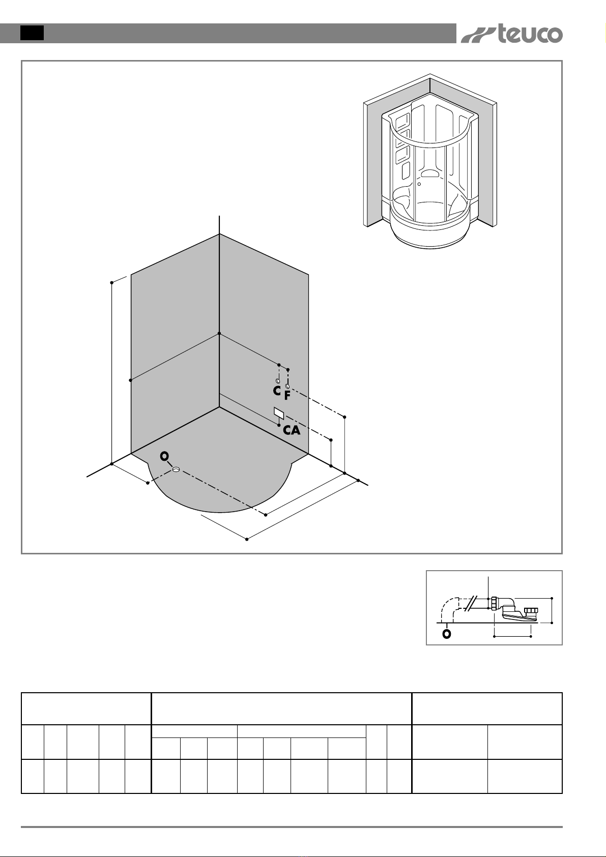
Measurements in mm.
C- Hot water connection for 1
/2"tap fittings
F- Cold water connection for tap fittings 1
/2"
O- Connection for drainage pipe recessed in floor Ø40mm
CA - Electrical connection for Hydromassage IPX5
(box with cable press PG 13.5)
N.B. Installation must take place once floors and
walls are completed.
The information and characteristics shown do not bind Teuco Guzzini Spa who reserves the right to make any modifications it retains necessary without any prior warning or notice of replacement.
The electrical installation must comply with the safety regulations for bathroom installation, as
described in the enclosed user’s manual.
Net
Weight
Kg.
175 300 270 291 1/2" Ø40
mm
Water
Content(1)
Kg.
Floor
Load
Kg/m2
ART. 220 M
Delivery
Weight
Kg.
4,6
Delivery
Volume
m3
TOP 8
Vers.
No. Jets
Water
Capacity
400
l/min. 280
l/min.
Air
Capacity
69÷16 2÷5
bar
Capacity
l/min
Min.Max.
Pressure
Supply
Drain
Conn.
HYDRAULIC CHARACTERISTICS
Hydromassage Multifunctions
2
Vert.
Jets
Foot
Jets
2WTX28 1,35
Whirlpool
Art.
Installed Power
Kw
(1) - At overflow level (2) - Before connecting the appliance, make sure that the voltage indicated on the rating plate is the same as that of the electric mains.
ELECTRICAL
CHARACTERISTICS(2)
PRE-INSTALLATION CARD ART. 220M (mm 1330 x 1330)
GB

Net
Weight
Kg.
209 300 300 344 1/2" Ø40
mm
Water
Content(1)
Kg.
Floor
Load
Kg/m2
ART. 220 S - 220 E
Delivery
Weight
Kg.
5,68
Delivery
Volume
m3
TOP 8
Vers.
No. Jets
Water
Capacity
400
l/min. 280
l/min.
Air
Capacity
69÷16 2÷5
bar
Capacity
l/min
Min.Max.
Pressure
Supply
Drain
Conn.
HYDRAULIC CHARACTERISTICS
Hydromassage Multifunctions
21
Vert.
Jets
Foot
Jets
Cent.
Sh.He.
620
1100 80
1330
350
1100
1425
1160
750
1100
1200
2000
2000
2315
C- Hot water connection for 1
/2" tap fittings
F- Cold water connection for tap fittings and sauna 1
/2"
O- Connection for drainage pipe recessed in floor
Ø40mm
CA - Electrical connection for Hydromassage IPX5
(box with cable press PG 13,5)
CA1 - Electrical connection for sauna and
Multifunctions
IPX5 (box with cable press PG 21)
N.B. Installation must take place once floors and
walls are completed.
The room in wich the sauna is to be installed
should be at least 240 cm high for service and
maintenance purposes.
97
160
Ø40
Siphon
19
The information and characteristics shown do not bind Teuco Guzzini Spa who reserves the right to make any modifications it retains necessary without any prior warning or notice of replacement.
Measurements in mm.
Electric connections must be effected in accordance with safety regulations for bathroom installation as
described in the enclosed instruction booklet.
Kw
Min. Max
Art.
5NTX18
5MTX18
2,4÷5
2,4÷5
-
0,05
Art.
2WTX28
Kw
1,35
Kw
ELECTRICAL
CHARACTERISTICS
(2)
Sauna
Multifunctions
Whirlpool
(1) - Overflow level. (2) - Before connecting the appliance, make sure that the voltage indicated on the rating plate is the same as that of the electric mains
PRE-INSTALLATION CARD ART. 220S-220E (mm 1330 x 1330) GB
20
ASSEMBLING THE CABIN
GB
M5x25
Ø5
C
C1 C1
C
4,2x45
Ø5
C1
A B
Y
X
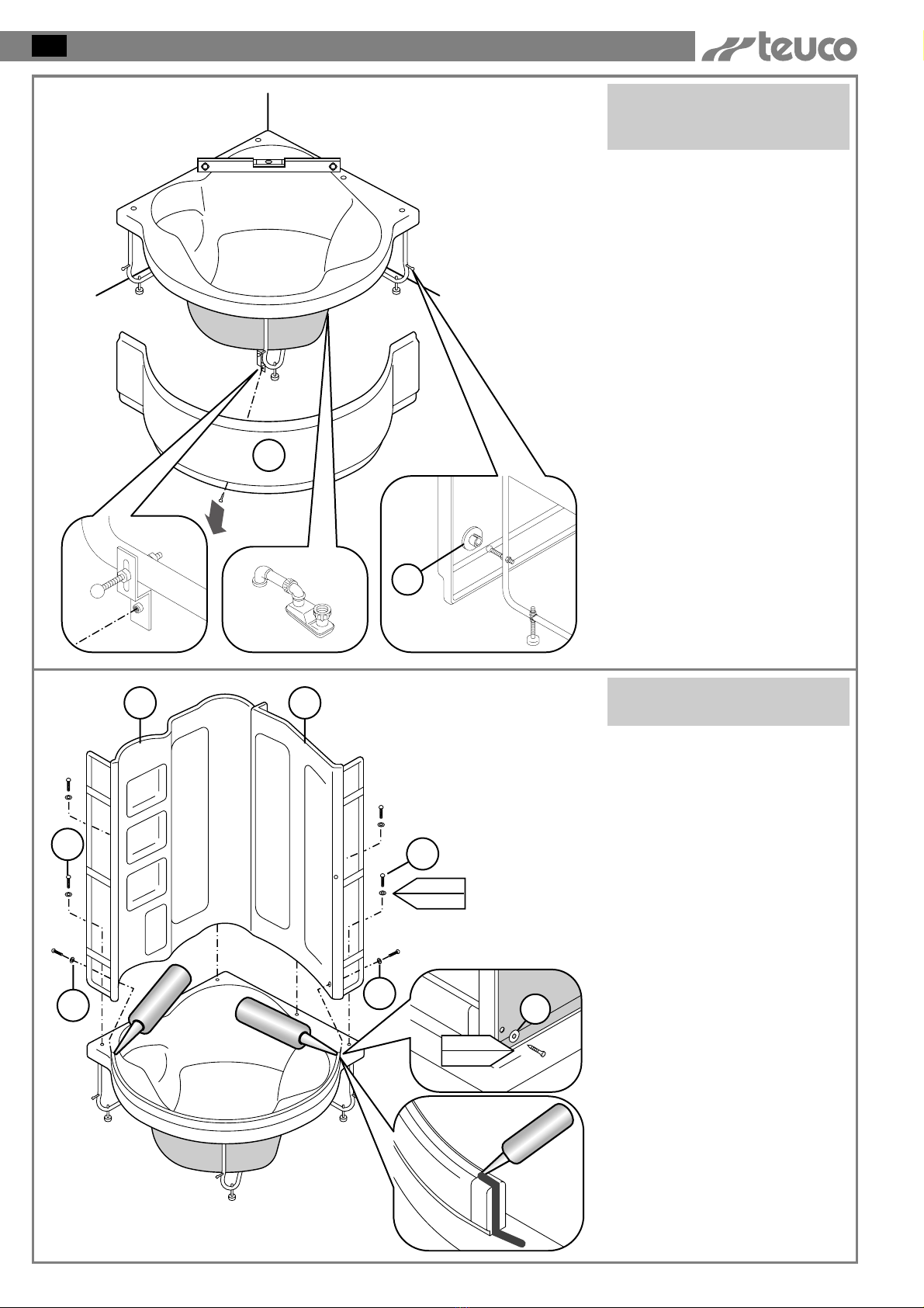
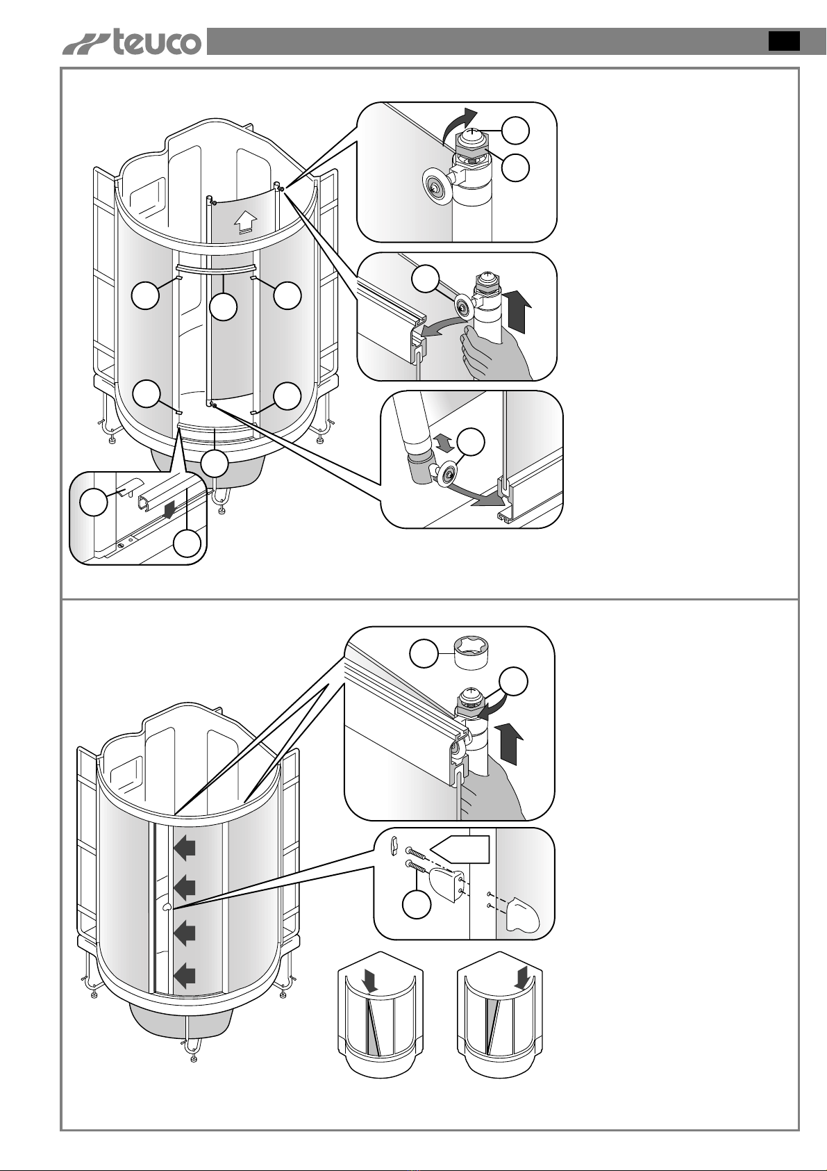
POSITIONING THE
BATHTUB
Remove the screws indicated by
the arrow in order to remove the
front panel.
Pull the bottom part of the panel
towards you so that the (Y) clips
come out of their respective
housings.
Place the bathtub in the corner of
the bathroom and make sure it is
on a level by using the appropriate
adjustable feet.
Prepare the drain connection using
the trap supplied.
N.B.: The unit must be installed
after the floor and walls have been
finished.
1
2
ASSEMBLING THE BACK
PANELS
Move the shower base away from
the corner in order to proceed with
the subsequent assembly steps.
Remove the screws (C1) from the
end of the lower track.
Apply silicone to the end of the
track as shown in the diagram.
Place the back panels (A) and (B)
onto the shower base and insert the
screws with the washers (C) to
fasten the panel frames to the
bathtub.
Fasten the panels to the track with
the screw (C1) removed earlier.
All screws and accessories which
are necessary for installation are
in the appropriate box
Bag (A) with screws for
step 2
21
ASSEMBLING THE CABIN GB
A1
C
M5
Ø5
B1
A
B
C
3
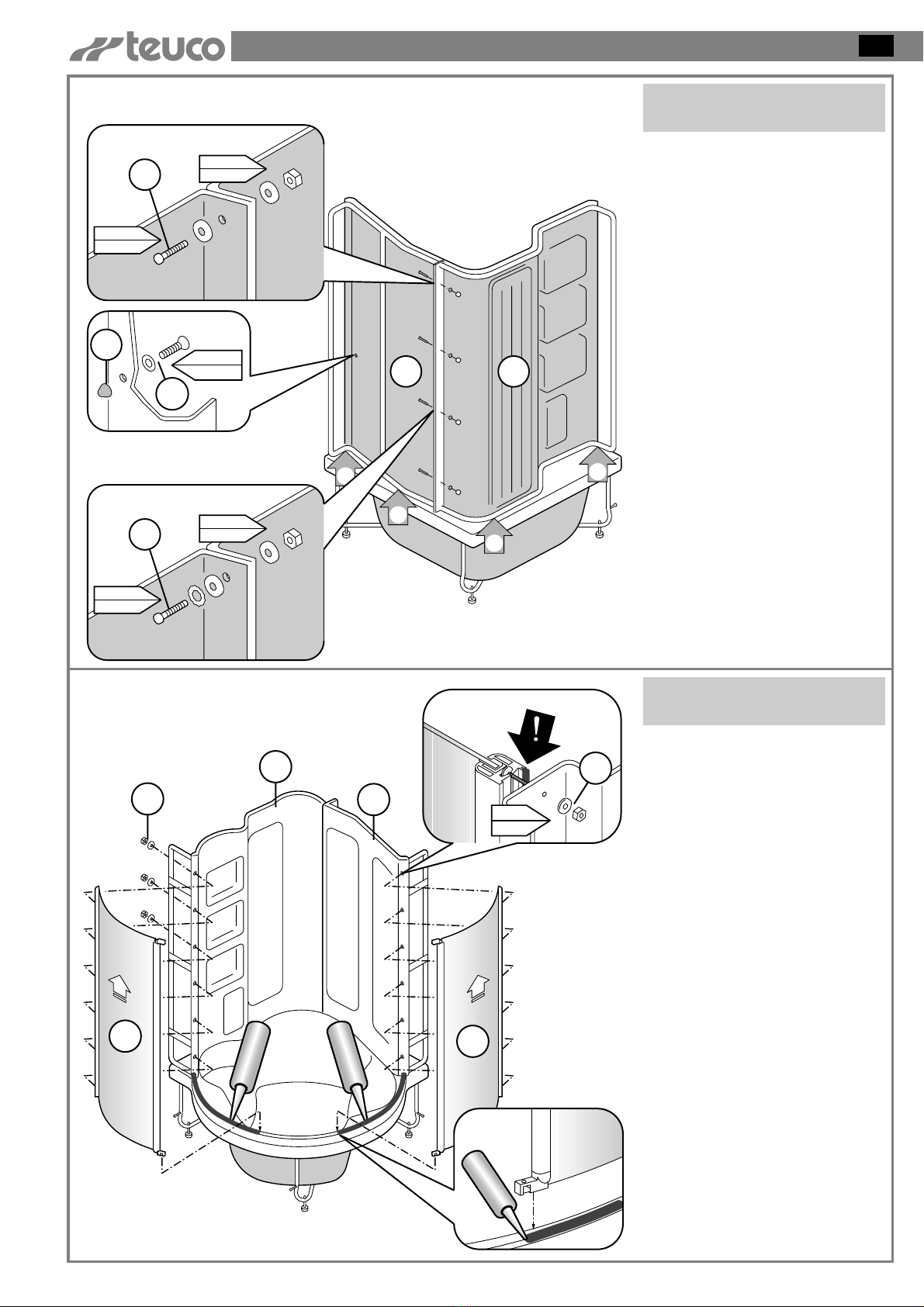
INSTALLING THE SIDE
PANELS
Apply silicone to the groove in the
track corresponding to the position
of the side panels, as indicated in
the diagram.
Slide the side panels (A1 and B1)
into the bottom track, leaving
several centimeters of space
between them and the back panels
(A and B).
Position the threaded pins on the
support for the side panel (A1 and
B1) so that they match up with the
holes on the back panel (A and B);
if necessary, use a 2.5 Allen
wrench.
Check that the seal (!) fits properly
along the entire length of the side
panel support.
Slide the side panels (A1 and B1)
so that they adhere to the back
panels (A and B) and fasten them
with the appropriate nuts and
washers (C).
Bag (D) - plastic accessories
C2
M5x25
Ø5
M5
Ø5
C
C
AB
C
C
M5x25
Ø5-Ø5
M5
Ø5
C2
C3
M3x8
Ø4
M
2a
Fasten the back panels (A) and (B)
together wit the appropriate screws,
nuts and washers (C2).
Fit the rubber doorstop (M) onto
the panel (B) and fasten it with the
screw and washer (C3).
To install the taps onto the back
panel, consult the attached
manual.
Bag (B) - screws for
steps 3 - 4 - 7
22
ASSEMBLING THE CABIN
GB
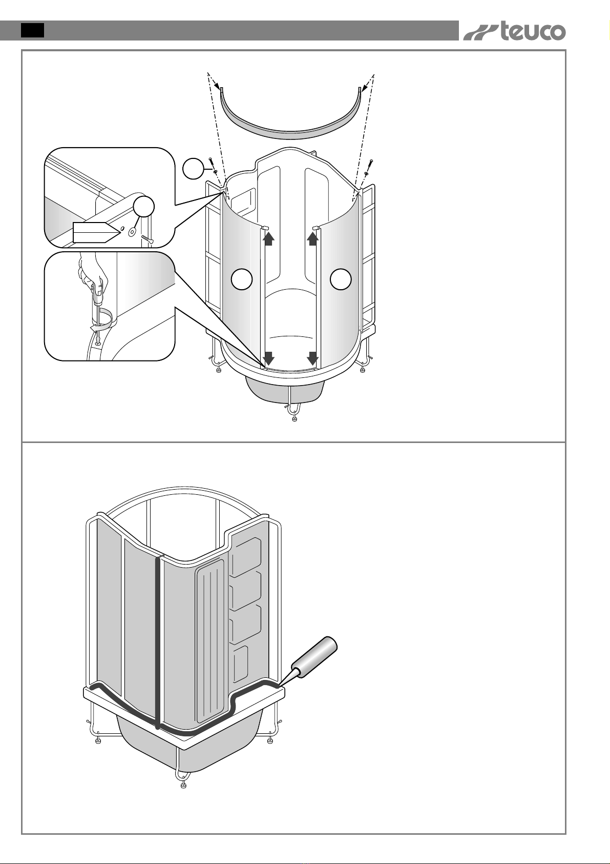
5APPLYING SILICONE
Apply a NEUTRAL (NON ACETIC)
silicone so as to prevent water from
leaking between the back panel
and the bathtub.
A1 B1
4,2x45
Ø5
C1
C1
INSTALLING THE TOP
TRACK
Remove the screws (C1) from the
ends of the top track.
Insert the track onto the ends of
the supports and fasten it to the
back panels using the screws and
washers (C1) that were removed
earlier.
Tighten the screws on the ends of
the side panel supports (A1) and
(B1).
4
23
ASSEMBLING THE CABIN GB
C
K
M4x30
D
AB
7CENTRING THE DOOR
Fit the handle onto the door
support and tighten the screws (C).
Then insert the piece of trim.
Close the door and make sure that
the magnetic seals are aligned
along the entire length of the door.
In the event that the seals do not
come together - as in case (A) or
case (B) - adjust the top slide
assembly indicated by the arrow.
- Lift the door, grasping it by the
supports.
- Tighten the screw (D) until the
magnetic seals are aligned.
N.B. After adjusting the slide
assembly, lock the nuts (D) in
place, inserting the covers (K) with
the inner wings facing outwards.
VY
Y
Y
Y
V
N
C
D
P
V
Y
FITTING THE DOOR
Insert the track covers (V) and the
end-trim (Y) into the top and
bottom tracks.
Turn the nut (D) until it is flush
with the top of the “C”screw.
Mount the door, hooking the wheels
(P) with the spring support onto the
lower track
Lift the door up so that the top
wheels (N) slide into the track.
6

24
ASSEMBLING THE CABIN
GB
G
G
8
MOUNTING THE SAUNA
DOME ONTO THE SHOWER
CABIN
Place the adhesive steam seal onto
the top edge of the back panels.
Position the suana onto the shower
cabin, making sure not to damage
the water and electrical hoses
attached to it. Make sure that the
steam seal (G) remains turned
toward the inside of the shower
cabin and that the centring pins fit
correctly into their seats in the
sauna dome.
ONLY FOR ARTICLES
220TOP - 220PLUS
25
CONNECTIONS FOR THE VARIOUS MODELS GB
C
F
A1
9
CA
P
N9
C
F
9
11
4
A2
11
A5
4
A4
A3
4
10
10
10
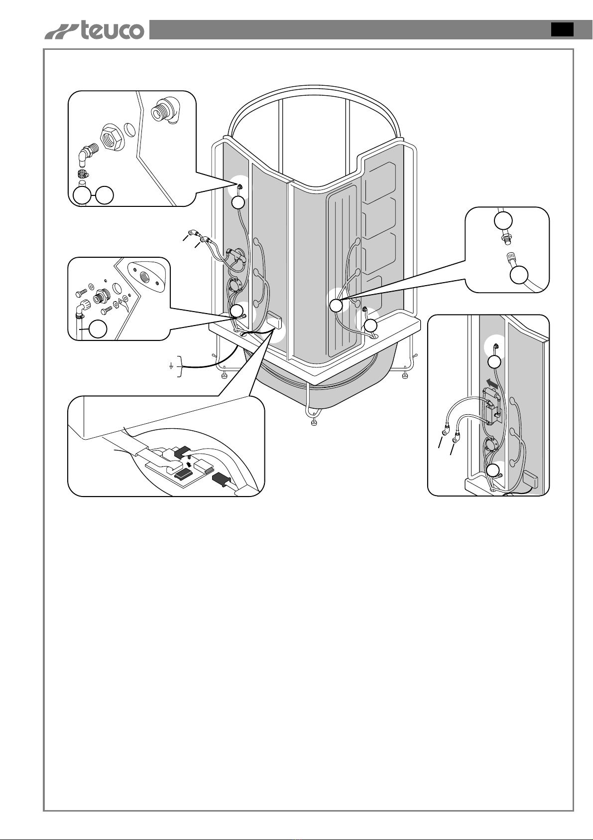
220M (MULTI) - Multifunction Hydroshower with whirlpool
C - Hot water connection.
Use a 60 cm flexible stainless
steel hose.
F - Cold water connection.
Use a 60 cm flexible stainless
steel hose.
A1 - Connection for the both shower
system using tube 9, which is
supplied and mounted on the
cabin and the diverter, and tube
11 for the foot massage unit.
A2 - Connection for the tap with tube
4 supplied and mounted on the
cabin and the diverter.
A3 - Connection for the cable coming
from the whirlpool power unit to
the control panel.
A4 - Connection for the tube for the
vertical massage.
The electrical installation must
comply with the safety regulations for
bathroom installation, as described in
the attached user’s manual.
CA- Electrical connection for the
IPX5 whirlpool (box with cable
clamp PG 13.5).
A5 - Diagram for the water connection
for the model with a thermostatic
mixer.
When installing the shut-off
valve, pay attention to the
direction of the arrow.
Blue
Yellow-Green
Brown

26
CONNECTIONS FOR THE VARIOUS MODELS
GB
C
F
C
F
11
4
A3 A7
4
D
3
3
A6
4
A5
D1 2 3
1 2 3
9
5
5
5
A2
A1
9 11
3
A4
5
9
F1
10
10
10
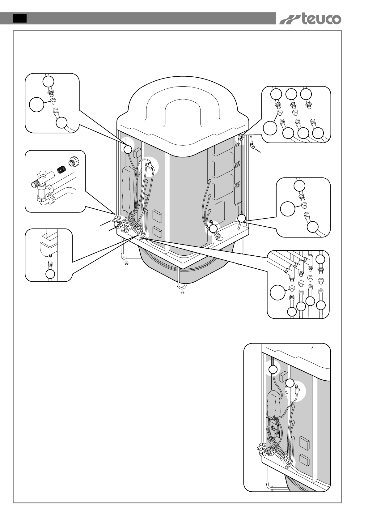
220S (TOP) - Top Multifunction Hydrosteam with whirlpool
WATER CONNECTIONS
Once the plugs (D) have been
removed, they should not be used
again.
C - Hot water connection.
Use a 60 cm flexible stainless
steel hose.
F - Cold water connection.
Use a 60 cm flexible stainless
steel hose.
F1 - Cold water connection for the
sauna.
A1 - Connection for the shower system
using hose 9, which is on the
shower cabin and connected to
the divertor, and for hose 11 for
the foot massage.
A2 - Connection for tube 5 for shower
head with nebulizer.
A3 - Connection for tap with hose 4
which is mounted on the cabin
and the diverter.
A4 - Connection for hose for the
vertical massage.
A5 - Connection of hoses 1-2-3 for
the sauna.
N.B.: Hoses 1 and 2 for the
decalcification system must always be
filled with water. Therefore, this
system must not be emptied during
installation.
A6 - Connection for hose 3 from the
sauna to the drain pipe.
A7 - Diagram for the water connection
for the model with a thermostatic
mixer.
When installing the shut-off
valve, pay attention to the
direction of the arrow.

27
CONNECTIONS FOR THE VARIOUS MODELS GB
CA
P
N
A3
A1
P
N
TALARM
CA1
P
N
A2
220S (TOP) - Top Multifunction Hydrosteam with whirlpool
ELECTRICAL CONNECTIONS
The electrical installation must comply
with the safety regulations for
bathroom installation, as described in
the attached user’s manual.
CA - Electrical connection for IPX5
whirlpool (box with cable clamp
PG 13.5).
CA1
- Electrical connection for the IPX5
sauna (box with cable clamp PG
21).
A1 - If the bathroom is equipped with
an alarm system, it can be
connected to the system using
wire (T) (see diagram).
A2 - Connection of the electric cable
to the sauna control panel.
A3 - Connection for the wire coming
from the whirlpool power unit to
the control panel.
Blue
Yellow green
Brown
Blue
Yellow green
Brown
Blue
Brown
28
CONNECTIONS FOR THE VARIOUS MODELS
GB
12
A3
A2
6
8
7
D
A6
11
C
F
D
3
3
A5
A4
D1 2 3
1 2 3
5
D
5
5
A1
3
F1
11
11
220E (PLUS) - Plus Multifunction Hydrosteam with whirlpool
WATER CONNECTIONS
Once the plugs (D) have been
removed, they should not be used
again.
C - Hot water connection.
Connect the tap with the filter.
F - Cold water connection.
Connect the tap with filter.
F1 - Cold water connection for the
sauna.
A1 - Connection for tube 5 for shower
head with nebulizer.
A2 - Cleaning of the taps with filter.
A3 - Connection for hose 12 for
drainage for the sliding rail.
A4 - Connection of hoses 1-2-3 for
the sauna.
N.B. Hoses 1 and 2 for the
decalcification system must always be
filled with water. Therefore, this
system must not be emptied during
installation.
A5 - Connection for hose 3 from the
sauna to the drain pipe.
A6 - Connection for hoses 6-7-8 for
the drainage system and for hose
11 for the foot massage.
A7 - Diagram for the water connection
for the model with a thermostatic
mixer.
When installing the shut-off
valve, pay attention to the
direction of the arrow.
5
9
A7

29
CONNECTIONS FOR THE VARIOUS MODELS GB
A4
A5
CA
P
N
A3
A1
P
N
TALARM
CA1
P
N
A2
220E (PLUS) - Plus Multifunction Hydrosteam with whirlpool
ELECTRICAL CONNECTIONS
The electrical installation must
comply with the safety regulations for
bathroom installation, as described in
the attached user’s manual.
CA - Electrical connection for IPX5
whirlpool (box with cable clamp
PG 13.5)
CA1
- Electrical connection for the
IPX5 sauna mulitfunction shower
(box with cable clamp PG 21)
A1 - If the bathroom is equipped with
an alarm system, it can be
connected to the system using
wire (T) (see diagram).
A2 - Connection of the electric cable
to the sauna control panel.
A3 - Connection for the wire coming
from the whirlpool power unit to
the control panel.
A4 - Connection for the wire coming
from the power unit to the sliding
rail. After the connection is
made, adjust the anti-spray
protection.
A5 - Connection for the wire coming
from the sauna to the wire from
the power unit.
Blue
Yellow green
Brown
Blue
Brown
Blue
Yellow green
Brown

30
CONNECTIONS FOR THE VARIOUS MODELS
GB
1
2
7
F
4
5
3
6
8
10
EQUIPOTENTIAL EARTHING
CONNECTION
Connect the metal parts of the
cabin with the yellow wire as
indicated in the diagram.
There is a terminal at point (8) for
the equipotential connection of the
other grounds present in the room.
N.B.: If one of the components
indicated in the diagram is not
present on the model purchased,
insulate the corresponding “fast
on”.
ONLY FOR ARTICLES
220TOP - 220PLUS
CONNECTION OF EARTHING WIRE (YELLOW/GREEN) TO THE FRAME
EMERGENCY TAP (ARTICLE 220E)
SHOWER SUPPORT ROD
SHUT-OFF VALVE FOR THERMOSTATIC MIXER
MIXER OR THERMOSTATIC MIXER
DEVIATOR OR SLIDING RAIL (ARTICLE 220E)
TAP
FRAME
PUMP SUPPORT
2
3
1
5
4
8
6
F
7
31
ASSEMBLING THE CABIN GB
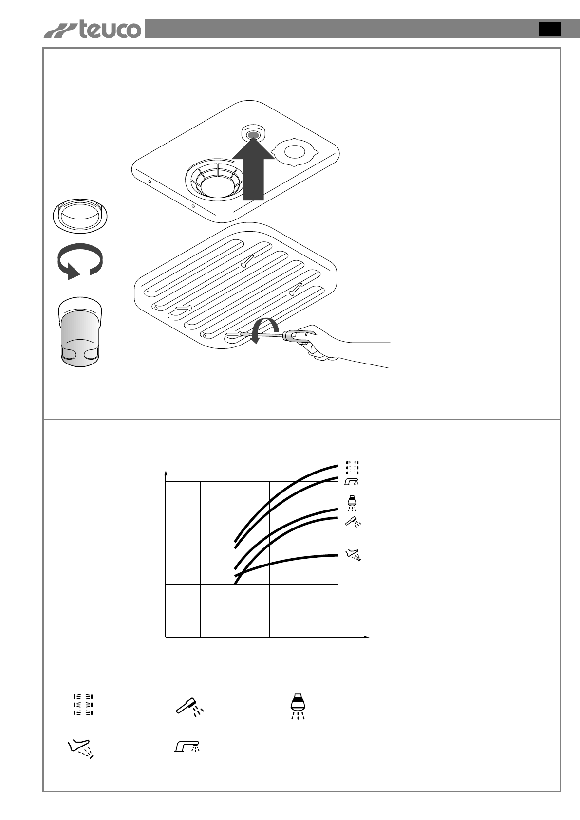
USING THE SHOWER FOR
THE FIRST TIME
Once all of the connections are
made and before fastening the
cabin to the wall, remove all of the
adhesive tags.
Run the regeneration and a sauna
cycle, following the instructions
contained in the attached user’s
manual.
Make sure that there are no water
leaks in the connections made and
that everything operates normally.
If the first time the sauna system is
turned on the control panel
displays the “DIAGNOSIS 9”
message, remove the grate and
press the button for resetting the
thermostat, indicated with the
arrow.
11
HYDRAULIC
CHARACTERISTICS
Diagram of the mixed water flow
for the various features.
12
l/min
15
10
5
012345
Bar
Vertical
massage
Foot
massage
Shower
massage
Spout from
overflow
Overhead fixed
shower with
nebulizer
32
ASSEMBLING THE CABIN
GB
C2
4,2x38
Ø5
C1
M5x16
Ø5-M5
T1
Y
T
S
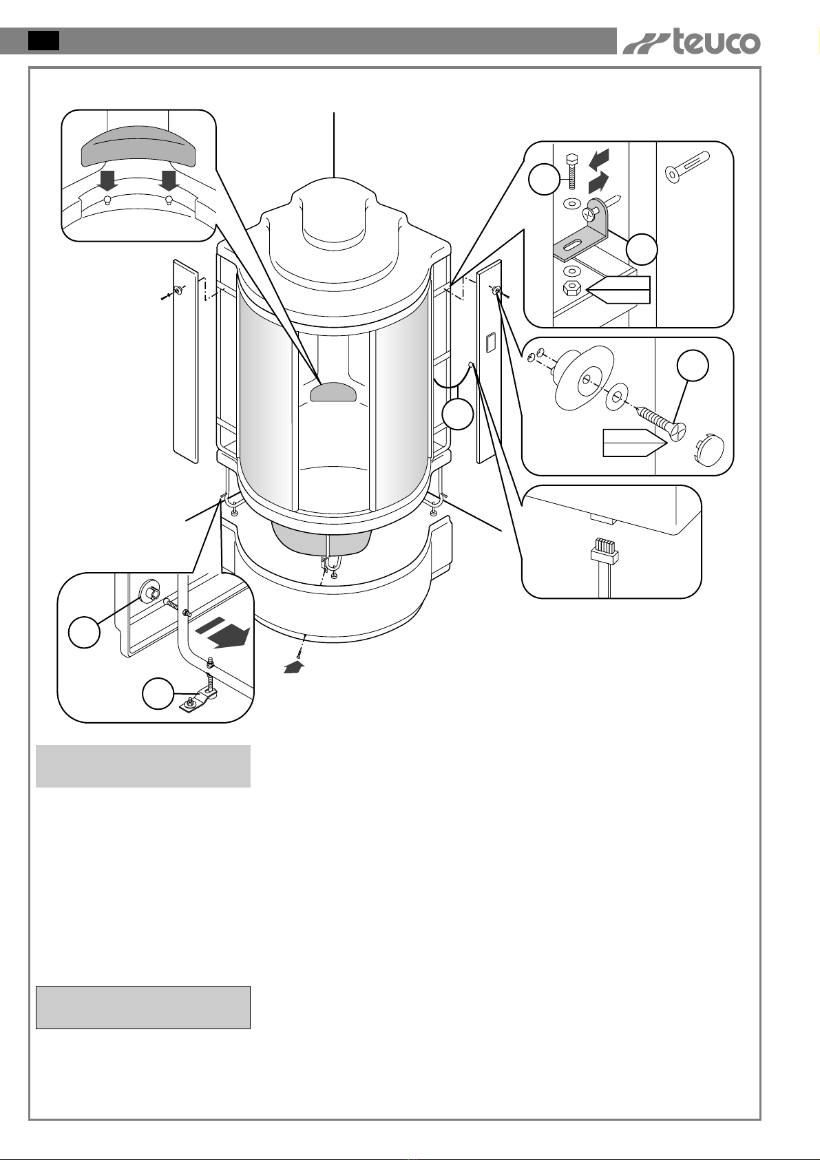
Fit the side panels by sliding it
down from the top so as to hook it
onto the support bracket on the
frame.
Fix the side panels by tightening
the towel-knob with the screws and
washers (C2); insert the trim.
Re-install the bathtub panel by
inserting the top edge underneath
the bathtub and pressing the clips
(Y) so that they go back into their
respective housings; fasten the
panel with the screw which was
removed previously.
FIXING THE SHOWER TO
THE WALL
Fix the bathtub to the floor with
plates (T) and screws and fischers.
Position the bracket (T1) on the
frame, drill a hole in the wall,
insert the screw with the fischer
and fasten the bracket (T1) to the
frame, tightening the screw with
the washer (C1).
13
Install the headrest by inserting it
onto the pens located on the
bathtub.
Connect the cable (S) on the
control panel to the side panel.
ONLY FOR
ARTICLE 220PLUS
Bag (C) - screws for step 13
Table of contents
Other Teuco Bathroom Fixture manuals

Teuco
Teuco 193 User manual

Teuco
Teuco Seaside User manual

Teuco
Teuco Endless Series User manual

Teuco
Teuco Infinity Series User manual

Teuco
Teuco KO40 User manual

Teuco
Teuco Multifunctional Light User manual

Teuco
Teuco P546S Series User manual

Teuco
Teuco H46M Series User manual

Teuco
Teuco CROMOEXPERIENCE User manual

Teuco
Teuco P551S Series User manual


Popular Bathroom Fixture manuals by other brands


Bradley
Bradley Aerada 1200 Series Installation

Franke
Franke RODX602E Installation and operating instructions

Delinia
Delinia LOA instruction manual

AL-MAR
AL-MAR E044180 Mounting instructions

Dreamline
Dreamline PRISM PLUS installation instructions

Hans Grohe
Hans Grohe Montreux 16320 Series Instructions for use/assembly instructions


