Texi Tronic 7 NF User manual

TEXI TRONIC 7 NF operation manual
Operation manual
High Speed Direct Drive
Automatic Lockstitch Sewing Machine
With Built-in Energ Saving Motor
and Needle feed
Tronic 7 NF

TEXI TRONIC 7 NF operation manual

TEXI TRONIC 7 NF operation manual
CONTENTS
Before operation ……………………………………………….……………………………………….………………………. 2
1. Specifications …………………………………………….……………………………………………….………………... 2
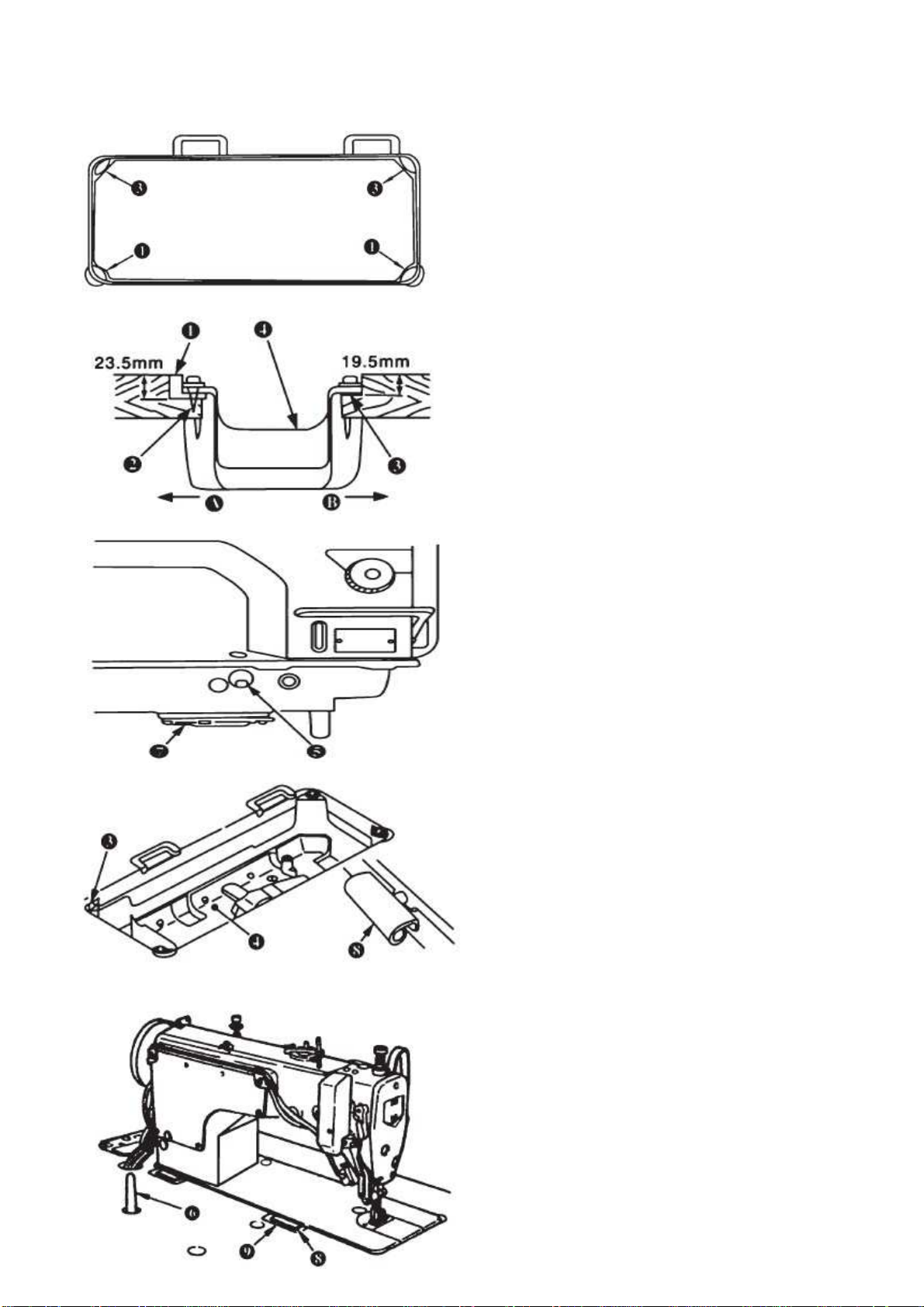
2. Installation ……………………………………………….………………………………………………………..………. 3
3. Adjusting the height of the knee lifter ………………………………………………………………………….………. 4
4. Installing the thread stand ……………………………………………………………………………………….……… 4
5. Lubrication ……………………………………………………………………………………………..…………………. 5
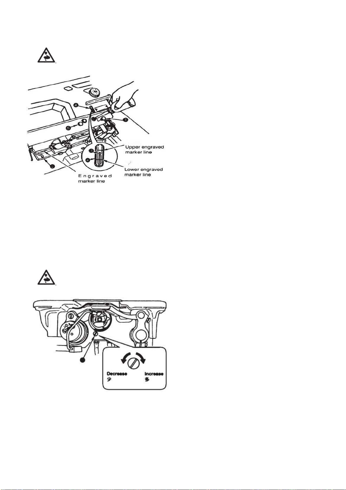
6. Adjusting the amount of oil in the hook ………………………………………………………………………..……… 5
7. Adjusting the amount of oil (oil splashes) in the hook ……………………………………………………...………… 6
8. Attaching the needle ……………………………………….……………………………………………..……………… 7
9. Setting the bobbin into the bobbin case …………………….……………………………………………….………… 7
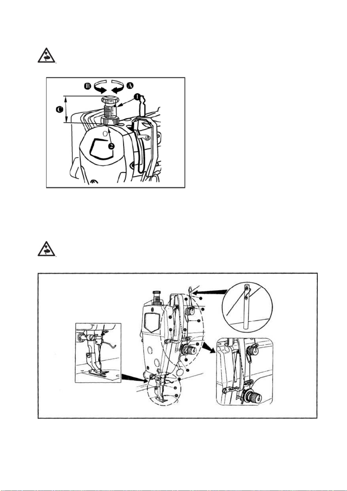
10. Adjusting the stitch length ……………………………………………………………………………………….………. 7
11. Presser foot pressure ……………………………………………………………………………………………...……… 8
12. Threading the machine head …………………………………………………………………………………………….. 8
13. Winding the bobbin thread ………………………………………………………………………………………..……… 9
14. Thread tension ………………………………………………………………………………………………………..…… 10
15. Thread take-up spring …………………………………………………………………………………………………..… 10
16. Adjusting the thread take-up stroke …………………………………………………………………………………...… 11
17. Adjusting the needle stop position …………………………………………………………………………….………… 11
18. Adjusting of the pedal …………………………………………………………………………………………..………… 12
19. Pedal operation ……………………………………………………………………………………….…………………… 12
20. Wiper ………………………………………………………………………………………………………….……………. 13
21. One-touch reverse stitching mechanism …………………………………………………………………..…………… 13
22. Needle bar and hook regulation……………………………….………………………………………………………… 14
23. Replacing counter knife and moving knife………………………...……………………………………………………. 15
24. Thread cutting regulation………………………..……………….………………………………………………..……… 16
25. The change of feed cloth………………………………………………………………………………………………….. 17
26. Height and tilt of the feed dog …………………………………….……………………………………………….……… 17
27. Adjusting the feed timing …………………………………………..……………………………………….……………… 19
28. Thread tension release releasing mechanism ……………………..………………………………….………………… 19
29. Micro-lifting mechanism of the presser foot …………………………..…………………………………..……………… 20
30. Caution when carrying or placing the sewing machine ……………………………………………………..………… 20
Ask your supplier about
CE Declaration of Conformity
1

TEXI Tronic 7 NF operation manual
BEFORE OPERATION
Caution: To avoid malfunction and damage of the machine, confirm the following.
•
Remove air-vent cap (red color) attached to the sewing machine bed.
•
Be sure to pour in the oil before using.
•
Before you put the machine into operation for the first time after the set-up, clean it thoroughly.
•
Remove all dust gathering during transportation and oil it well.
•
Confirm that the voltage has been correctly set
•
Confirm that the power plug has been properly connected to the power supply.
•
Never use the machine in the state where the voltage type is different from the designated one.
•
Confirm that the direction of rotation of the motor pulley is correct.
•
Do not tilt the sewing machine head toward this side since oil leakage or parts breakage occurs.
A safety switch is installed so that the sewing machine cannot be operated with the head tilted. When operate the sewing
machine, turn on the power switch after properly setting the head on the table.
1. Specifications
Needle bar stroke 32.7mm
Sewing speed 4000 rpm
Stitch length 4mm
Needle DPx5 #9 - #18
Presser foot lifter 13 mm
Oil Vaseline oil (e.g. Spirit 2)
Rated power 500W
2

TEXI Tronic 7 NF operation manual
2. Installation
Installing the oil pan:
1. The oil pan should rest on the four corners of the machine
table groove;
2. Two rubber seats (1) for supporting the head portion are
fixed on the extended portion of the table by hitting the nails
(2) (on the operator side „A”), and the other two rubber
cushion seats (3) are fixed by hitting the nails (2) (together
with machine hinge plate asm, on the hinged side „B”). Then,
oil pan (4) is placed;
3. Remove air vent cap (5) attached to the machine bed. (Be
sure to attach cap when the machine head is removed from
the machine table).
4. Fit hinge (8) into the opening in the machine bed, and fit
the machine head to table rubber hinge (9) before
placing the machine head on cushions (3) on the four
corners.
Caution: If the sewing machine is operated without
removing air vent cap (5), oil leakage from gearbox portion
(7) may occur.
3

TEXI Tronic 7 NF operation manual
3. Adjusting the height of the knee lifter
Warning: Turn OFF the power before starting the work as to prevent accident caused by abrupt start of the
sewing machine.
1. The standard height of the presser foot lifted is 10 mm.
2. You can adjust the presser foot lift up to 15 mm using
knee lifter adjust screw (1).
Caution: Do not operate the sewing machine when the presser
foot (3) is lifter 10 mm or more, since the needle bar (2) will be
get contact with the presser foot (3).
4. Installing the thread stand
1. Assemble the thread stand unit, and insert it in the
hole in the machine table.
2. Tighten lockout (1) to fix the thread stand.
3. For ceiling wiring, pass the power cord through spool
rest rod (2).
4

TEXI Tronic 7 NF operation manual
5. Lubrication
Warning: Turn OFF the power before starting the work as to prevent accident caused by abrupt start of the
sewing machine.
Fill the oil tank with oil for hook lubrication before the sewing
machine.
1. Tilt the machine head until it comes in contact with the
head support rod.
2. Remove oil hole cap (1) and fill the oil tank with oiler
supplied with the machine.
3. The amount of oil should be reached up to the engraved
marker line of oil tank (2). If the oil is filled excessively, it
will leak from the air vent hole in the oil tank and proper
lubrication will be not performed. So, be careful.
4. When you operate the sewing machine, refill oil if the top
end of oil amount indicating rod (3) comes down to the
lower engraved marker line of oil amount indicating
window (4).
Caution: When you use a new sewing machine or a sewing
machine after an extended period of disuse, run your
machine at 3,000 to 3,500 rpm for the purpose o break-in.
Do not remove rubber plug (5).
6. Adjusting the amount of oil in the hook
Warning: Turn OFF the power before starting the work as to prevent accident caused by abrupt start of the
sewing machine.
Adjustment of the amount of oil in the hook is performed with
oil amount adjustment screw (1). Adjustment procedure:
Tighten (turn clockwise) oil amount adjustment screw (1) to
increase the amount of oil in the hook, or loosen (turn
counterclockwise) to decrease it.
Caution: When using RP hook (hook for dry head) for the SS
type, be sure to loosen the oil amount adjustment screw up to
the minimum so as to reduce the oil amount in the hook.
Never drain the oil in the oil tank even when RP hook (hook
for dry head) is used.
5

TEXI Tronic 7 NF operation manual
7. Adjusting the amount of oil (oil splashes) in the hook
Warning: Be extremely careful about the operation of the machine since the amount of oil has to be checked
by turning the hook when the hook is at a high speed.
I. How to confirm the amount of oil (oil splashes)
When carrying out the procedure described below in 2, remove the slide plate and take extreme caution not to allow your
fingers to come in contact with the hook.
1) If the machine has not been sufficiently warmed up for operation, make the machine run idle for approximately three
minutes. (Moderate intermittent operation).
2) Place the amount of oil (oil splashes) confirmation paper under the hook while the sewing machine is in operation.
3) Confirm that oil exists in the oil tan.
4) Confirmation of the amount of oil should be completed in five seconds. (Check the period of time with a watch).
II. Sample showing the appropriate amount of oil
1. The amount of oil shown in the samples below should be finely adjusted in accordance with sewing processes, Be careful
not to excessively increase/decrease the amount of oil in the hook. (if the amount of oil is too little, the hook will be seized
(the hook will be hot). If the amount of oil is too much, the sewing product may be stained with oil).
2. Adjust the amount of oil in the hook so that the oil amount (oil splashes) should not change while checking the oil amount
three times (on the three sheets of paper).
6

TEXI Tronic 7 NF operation manual
8. Attaching the needle
Warning: Turn OFF the power before starting the work as to prevent accident caused by abrupt start of the
sewing machine.
A needle 135x5 / 134R / DPx5 should be used. Select a
proper needle size according to the count of thread and the
type of material used.
1. Turn the hand-wheel until the needle bar reaches the
highest point of its stroke.
2. Loosen screw (2), and hold needle (1) with its indented
part “A” facing exactly to the right in direction “B”.
3. Insert the needle fully into the hole in the needle bar in
the direction of the arrow until the end of hole is reached.
4. Securely tighten screw (2).
5. Check that long groove “C” of the needle is facing exactly
to the left in direction “D”.
Caution: When filament thread is used, if the indented part of the needle is tilted toward operator's side, the loop of thread
becomes unstable, As a result, hangnail of thread or thread breakage may occur. For such thread, in order to avoid such
phenomenon occur, it is effective to attach the needle with its indented part slightly slanting on the rear side.
9. Setting the bobbin into the bobbin case
1. Install the bobbin in the bobbin case so that the thread
wound direction is clockwise.
2. Pass the thread through thread slit “A”, and pull the
thread in direction “B”. By so doing, the thread will pass
under the tension spring and come out from notch “B”.
3. Check that the bobbin rotates in the direction of the arrow
when thread “C” is pulled.
10. Adjusting the stitch length
1. Turn stitch length dial (1) in the direction of the arrow,
and align the desired number to marker dot “A” on the
machine arm.
2. The dial calibration is in millimeters.
3. When you want to decrease the stitch length, turn stitch
length dial (1) while pressing feed lever (2) in the
direction of the arrow.
7

TEXI Tronic 7 NF operation manual
11. Presser foot pressure
Warning: Turn OFF the power before starting the work as to prevent accident caused by abrupt start of the
sewing machine.
1. Loosen nut (2). As you turn presser spring
regulator (1) clockwise (in direction A), the presser
foot pressure will be increased.
2. As you turn the presser spring regulator
counterclockwise (in direction B), the pressure will
be decreased.
3. After adjustment, tighten nut (2).
4. For general fabrics, the standard height of
the presser spring regulator is 32 to 34 mm (4.5 kg).
12. Threading the machine head
Warning: Turn OFF the power before starting the work as to prevent accident caused by abrupt start of the
sewing machine
8

TEXI Tronic 7 NF operation manual
13. Winding the bobbin thread
1. Insert the bobbin deep into the bobbin winder spindle (1)
until it cannot go further.
2. Pass the bobbin thread from the spool rested on the right
side of the thread stand following the order as shown on
the left. Then, wind clockwise the end of the bobbin
thread on the bobbin several times. (as for the aluminum
bobbin, after winding clockwise the end of the bobbin
thread , wind counter-clockwise the thread coming from
the bobbin thread tension several times in order to wind
the bobbin thread with ease.)
3. Push the bobbin winder trip latch (2) in the direction “A”
and start the sewing machine. The bobbin rotates in the
direction C and the bobbin thread is wound up. The
bobbin winder spindle (1) automatically stops as soon as
the winding is finished.
4. Remove the bobbin and cut the bobbin thread with the
thread cut retainer (3).
5. To adjust the winding amount of the bobbin thread,
loosen the setscrew (4) and move the bobbin adjusting
plate (5) to the direction “A” or “B”. Then, tighten the
setscrew (4). (To the direction “A” : Decrease; to the
direction “B” : Increase.)
6. In case that the bobbin thread is not wound evenly on the
bobbin, loosen the nut (6) and turn the bobbin thread
tension to adjust the height of the thread tension disk (7).
It is the standard that the center of the bobbin is as high
as the center of the thread tension disk.
Move the position of the thread tension disk (7) to the
direction “A” as shown in the figure above when the
winding amount of the lower part of the bobbin is
excessive and to the direction “B” when the winding
amount of the upper part of the bobbin is excessive.
After the adjustment, tighten the nut (6).
7. To adjust the tension of the bobbin winder, turn the
thread tension nut (8).
Caution:
1. When winding the bobbin thread, start the winding in the
state that the thread between the bobbin and thread
tension disk (7) is tense.
2. When winding the bobbin thread in the state that wing is
not performed, remove the needle thread from the thread
path of thread take-up and remove the bobbin from the
hook.
9

TEXI Tronic 7 NF operation manual
14. Thread tension
Adjusting the needle thread tension
1. As you turn thread tension nut (1) clockwise (in direction
“A”), the thread remaining on the needle after thread
trimming will be shorter.
2. As you turn nut (1) counter-clockwise (in direction “B”),
the thread length will be longer.
3. As you turn thread tension nut (2) clockwise (in direction
“C”), the needle thread tension will be increased.
4. As you turn nut (2) counter-clockwise (in direction “D”),
the needle thread tension will be decreased.
Adjusting the bobbin thread tension
1. As you turn tension adjust screw (3) clockwise (in
direction “E”), the bobbin thread tension will be increased.
2. As you turn screw (3) counterclockwise (in direction “F”),
the bobbin thread tension will be decreased.
15. Thread take-up spring
Changing the stroke of thread take-up spring
1. Loosen set screw (2).
2. As you turn tension post (3) clockwise (in direction A), the
stroke of the thread take-up spring will be increased.
3. As you turn tension post (3) counter-clockwise (in
direction B), the stroke will be decreased.
Changing the pressure of thread take-up spring (1)
1. Loosen setscrew (2), and remove thread tension (5).
2. Loosen setscrew (4). As you turn tension post (3)
clockwise (in direction A), the pressure will be increased.
3. As you turn tension post (3) counterclockwise (in
direction B), the pressure will be decreased.
Usually, all the take-up spring has been adjusted well on factory setting, only when sew special material thread, it need to be
adjusted again.
To judge the work of the thread take-up spring, confirm whether or not the thread take-up spring works up to the last before
the needle thread is pulled out from (A) when pulling out needle thread in the direction of (B) after the pressure of the thread
take-up spring has been performed. When it does not work up to the last, decrease the pressure of the thread take-up spring.
In addition, the stroke of the thread take-up spring is excessively small, the spring does not work properly. For the general
fabrics, a stroke of 10 to 13 mm is proper.
10

TEXI Tronic 7 NF operation manual
16. Adjusting the thread take-up stroke
1. When sewing heavy materials, move thread guide (1) to
the left (in direction A) to increase the length of thread
pulled out by the thread take-up.
2. When sewing light materials, move thread guide (1) to
the right (in direction B) to decrease the length of thread
pulled out by the thread take-up.
3. Normally, the standard is marker line C of thread guide
(1) is aligned with the center of the screw
17. Adjusting the needle stop position
Warning: Turn OFF the power before starting the work as to prevent accident caused by abrupt start of the
sewing machine.
Stop position after thread trimming
1. The standard needle stop position is obtained by aligning
marker dot A on the pulley cover with white marker dot B
on the hand-wheel.
2. Stop the needle in its highest position, loosen screw (1) to
perform adjustment within the slot of the screw.
The needle stop timing is advanced if you move the screw in
direction C.
The needle stop timing is delayed if you move the screw in
direction D
Lower stop position
The lower needle stop position when the pedal is returned to
the neutral position after the front part of the pedal is depressed
can be adjusted as follows:
1. Stop needle (1) in its lowest position.
2. Loosen screw (2), and make Adjustment within the slot of
the screw.
Moving the screw in direction A advances the needle stop
timing.
Moving the screw in direction B delays the timing
11

TEXI Tronic 7 NF operation manual
18. Adjusting of the pedal
Warning: Turn OFF the power before starting the work as to prevent accident caused by abrupt start of the
sewing machine.
Installing the connecting rod
Move pedal (3) to the right or left as illustrated by the arrows so that
motor control lever (1) and connecting rod (2) are straightened.
Adjusting the pedal angle
1. The pedal tilt can be freely adjusted by changing the length of
the connecting rod.
2. Loosen adjust screw (4) and adjust the length of
connecting rod (2).
19. Pedal operation
The pedal is operated in the following four steps:
The machine runs at low sewing speed when you lightly
depress the front part of the pedal B.
The machine runs at high sewing speed when you further
depress the front part of the pedal A. (If the automatic reverse
feed stitching has been preset, the machine runs at high speed
after it completes reverse feed stitching).
The machine trims threads when you fully depress the back part
of the pedal D.
If your machine is provided with the Auto-lifter, an addition step
is given between the machine stop and thread-trimming step.
The presser foot goes up when you lightly depress the back part
of the pedal C and if you further depress the back part, the
thread trimmer is actuated.
If you reset the pedal to its neutral position during the
automatic reverse feed stitching at seam start, the machine
stops after it completes the reverse feed stitching;
The machine will perform normal thread trimming even if you
depress the back part of the pedal immediately following high or
low speed sewing.
The machine will completely perform thread trimming even if
you reset the pedal to its neutral position immediately after the
machine started thread trimming action.
When the machine stops with its needle down, and if you want to
bring the needle up, depress the back part of the pedal once .
12

TEXI Tronic 7 NF operation manual
20. Wiper
Positioning the wiper
Adjust the position of the wiper according to the thickness of the
material sewn. The adjustment procedure is as follows:
1. Turn the hand-wheel in the normal direction of rotation to
align white marker dot (1) on the hand-wheel with marker
dot (2) on the machine arm.
2. Adjust the distance between the flat part of the wiper and
the center of the needle to 1 mm. Tighten wiper adjust
screw (3) so that the wiper is pressed and fixed by wiper
collar (4).
3. When the wiper is unnecessary, turn wiper switch (5) OFF.
21. One-touch type reverse feed stitching mechanism
Warning: Turn OFF the power before starting the work as to prevent accident caused by abrupt
start of the sewing machine.
How to operate
1. The moment switch lever (1) is pressed, the machine
performs reverse feed stitching.
2. The machine performs reverse feed stitching as long as
the switch lever is held depressed.
3. The machine resumes normal feed stitching the moment
the switch lever is released.
Height of the switch
1. Switch (1) can be used in two positions by turning it.
2. In addition, when you desire to lower the position of
switch (1), loosen setscrew (3) located in the back of the
machine head and lower switch base (4).
13

TEXI Tronic 7 NF operation manual
22. Needle bar and hook regulation
Warning: Turn OFF the power before starting the work as to prevent accident caused by abrupt start of the
sewing machine.
1. Turn the hand-wheel to bright the needle bar down to the
lowest point of its stroke, and loosen setscrew (1).
2. Adjusting the needle bar height:
1) While using DB needle, align marker line A with the
bottom end of needle bar lower bushing (3), then
tighten setscrew (1).
2) While using DA needle, align marker line C with the
bottom end of needle bar lower bushing (3), then
tighten setscrew (1).
3. Locate the hook position:
1) While using DB needle, loosen the three hook set
screw, turn the hand-wheel, and align marker line B
on ascending needle bar 2 with the bottom end of
needle bar lower bushing (3).
2) While using DA needle, loosen the three hook set
screw, turn the hand-wheel, and align marker line D
on ascending needle bar 2 with the bottom end of
needle bar lower bushing (3).
4. After making the adjustments mentioned in the above
steps, align hook blade point (5) with the center of
needle (4). Provide a clearance of 0.04mm to 0.10 mm
(reference value) between the needle and the hook, then
securely tighten setscrews in the hook.
Caution: If the clearance between the blade point of hook and
the needle is smaller than the specified value , the blade point
of hook will be damaged. If the clearance is larger, stitch skip-
ping will result. Use a hook of the same part No. when
replacing your hook with a new one.
14

TEXI Tronic 7 NF operation manual
23. Replacing counter knife and moving knife
Warning: Turn OFF the power before starting the work as to prevent accident caused by abrupt start of the sewing
machine.
Counter Knife Dismantling
1. Head down.
2. Loosen Screw (1), Remove the positioning hook of rotating
shuttle (2).
3. Loosen screw (3), Remove the stationary knife (4).
*Method of installation, please follow the above steps on the
contrary
The grinding method of stationary knife:
If the knife become blunt, According to below picture, sharpening
stationary knife (4) in grindstone (5).
Moving Knives Dismantling
1. Remove the needle.
2. Lift the presser foot with the presser foot lifter.
3. Loosen 2 pcs of screw (1), then take out the needle plate.
4. Rotating the hand wheel, make the needle bar rise to the
highest position.
5. Head down.
6. Push the tangent driven crank (3) until you can see screw (4).
7. Loosen 2 pcs of screw (4), then take out rotation knives (5)
*Method of installation, please follow the above steps on the
contrary.
15

TEXI Tronic 7 NF operation manual
24. Thread Cutting Regulation
Warning: Turn OFF the power before starting the work as to prevent accident caused by abrupt start of the sewing
machine.
Thread cutter cam position regulation
Turn the machine’s pulley. The needle bar will rise to 5 mm from the lower dead point, and the thread cutting cam will be
pressed in and will push the roller ball, causing contact with the groove of the thread cutting cam (1). Then use fixing screw
(2) for temporary fastening. Put on the thread cutting cam (4) while loosening screw (2) in order to set the cam (1). The
distance between the cam and the thread cutting drive shaft should be equal to 0.5 mm. Fasten the fixing screw (2).
Counter knife and moving knife position regulation
When the thread cutting drive shaft head (3) cross the cam, a 0.2 – 0.5 mm meshing between the front plane of the counter
knife (8) and the edge of the moving knife (7) occurs. If cutting does not take place, shift the knife lever (6) so that the thread
cutting drive shaft crosses the cam (1) so that the front plane of the counter knife (8) and the edge of the moving knife (7)
meshes, and then fasten screw (5).
16

TEXI Tronic 7 NF operation manual
25. The change of feed cloth
Warning: Turn OFF the power before starting the work as to prevent accident caused by abrupt start of the
sewing machine.
The needle bar connecting rod (2) and the crank (1) are connected with screw, The method of feed cloth is needle feeding.
The needle bar connecting rod (2) and the needle bar base (3) are connected with screw. The method of feed cloth is feed
dog feeding.
Changing feeding method should notice:
1. Needle plate, feed dog and presser foot need to be changed into the needle plate, feed dog and presser foot of
corresponding feed way, and readjust synchronism of machine needle and feed dog.
Synchronous adjustment method:
•
Feed dog feeding, when feed dog is in falling direction, upper plane of feed dog and needle plate alignment, when the
needle in the down direction, top of pinhole and needle plate alignment, then can ensure synchronism;
•
Needle feeding, when feed dog on the rise direction, upper plane of feed dog and needle plate alignment, when the
needle in the down direction, top of pinhole and needle plate alignment, then can ensure synchronism. Needle
feeding and feed dog feeding, synchronous phase is different about 180°)
2. Need to readjust the Thread trimming cam position; ( adjust in the position of upper needle stop or lower needle stop).
3. Need to readjust the needle and the hook relations.
4. After change the feed method, ensure the machine needle and needle plate pinhole center or machine needle and feed
dog center consistent.
26. Height and tilt of the feed dog
Warning: Turn OFF the power before starting the work as to prevent accident caused by abrupt start of the sewing
machine.
Height of the feed dog is adjusted so that the feed dog protrudes from the throat plate surface by 0.75 to 0.85 mm (1 mm for
Heavy type). Adjust the height in accordance with the material to be used.
Adjusting the height and tilt of the feed dog:
1. Loosen setscrew (2) in feed bar driving shaft (1) and setscrew (4) in feed bar rocker shaft (3).
2. Height and tilt of the feed dog will change by turning both shafts (1) and (3) with a screwdriver.
3. For the relation between the rotating direction of each shaft and tilt of feed bar (6), refer to the figure on the left.
4. After the adjustment, securely tighten the setscrews. (Tighten setscrews (2) and (4) in the state that shafts (1) and (3) are
pushed against the hand-wheel side.)
17

TEXI Tronic 7 NF operation manual
Caution:
1. If the tilt of the feed dog is adjusted with one shaft only, the height of the feed dog changes. Be sure to adjust it with both
shafts.
2. Movement position of the feed dog may be shifted depending on the adjusting position of the shaft. At this time, loosen
setscrew (5) in feed rocker shaft arm (7) and adjust the movement position.
18
Table of contents
Other Texi Sewing Machine manuals

Texi
Texi Art Auto 2 User manual

Texi
Texi 1501 TS PREMIUM User manual

Texi
Texi Ziggy User manual

Texi
Texi Catenaccio User manual

Texi
Texi Tronic 1 User manual

Texi
Texi joylock 2/4 User manual

Texi
Texi Treccia User manual

Texi
Texi ART AUTO User manual

Texi
Texi Catenaccio User manual

Texi
Texi Tronic 1 NEO User manual